Chint Power CPS SCA50KTL-DO/US-480 User manual

物料:
CPS SCA50/60KTL-DO/US-480 英文版说明书
料号:
9.0020.0334A0
纸张大小:
大32 开
封面制作要求:
200g 铜版纸附亚膜封面彩色印刷
内页制作要求:
70g 除静电双胶纸黑白印刷

2
CPS SCA Series Grid-tied PV Inverter
CPS SCA50KTL-DO/US-480
and SCA60KTL-DO/US-480
Installation and Operation Manual - Rev 2.1
CHINT POWER SYSTEMS AMERICA CO.

Table of Contents
Before You Start…................................................................................................1
Chapter 1 IMPORTANT SAFETY INSTRUCTIONS ......................................2
Chapter 2 Overview .............................................................................................5
2.1 Inverter for grid-tied PV systems.....................................................5
2.2 Product Features...............................................................................5
2.3 Product Protection Functions...........................................................6
2.4 Schematic Diagram and Circuit Design ...........................................7
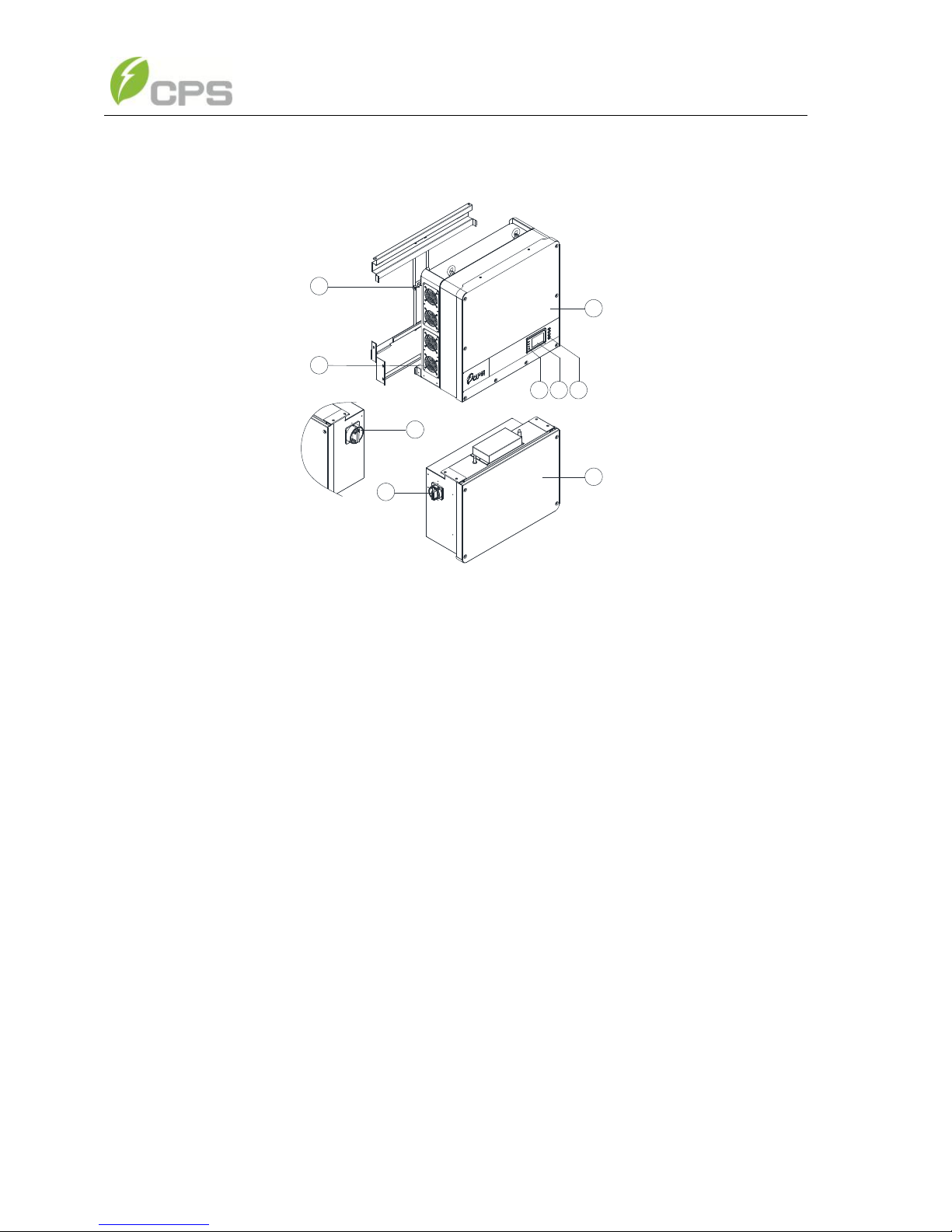
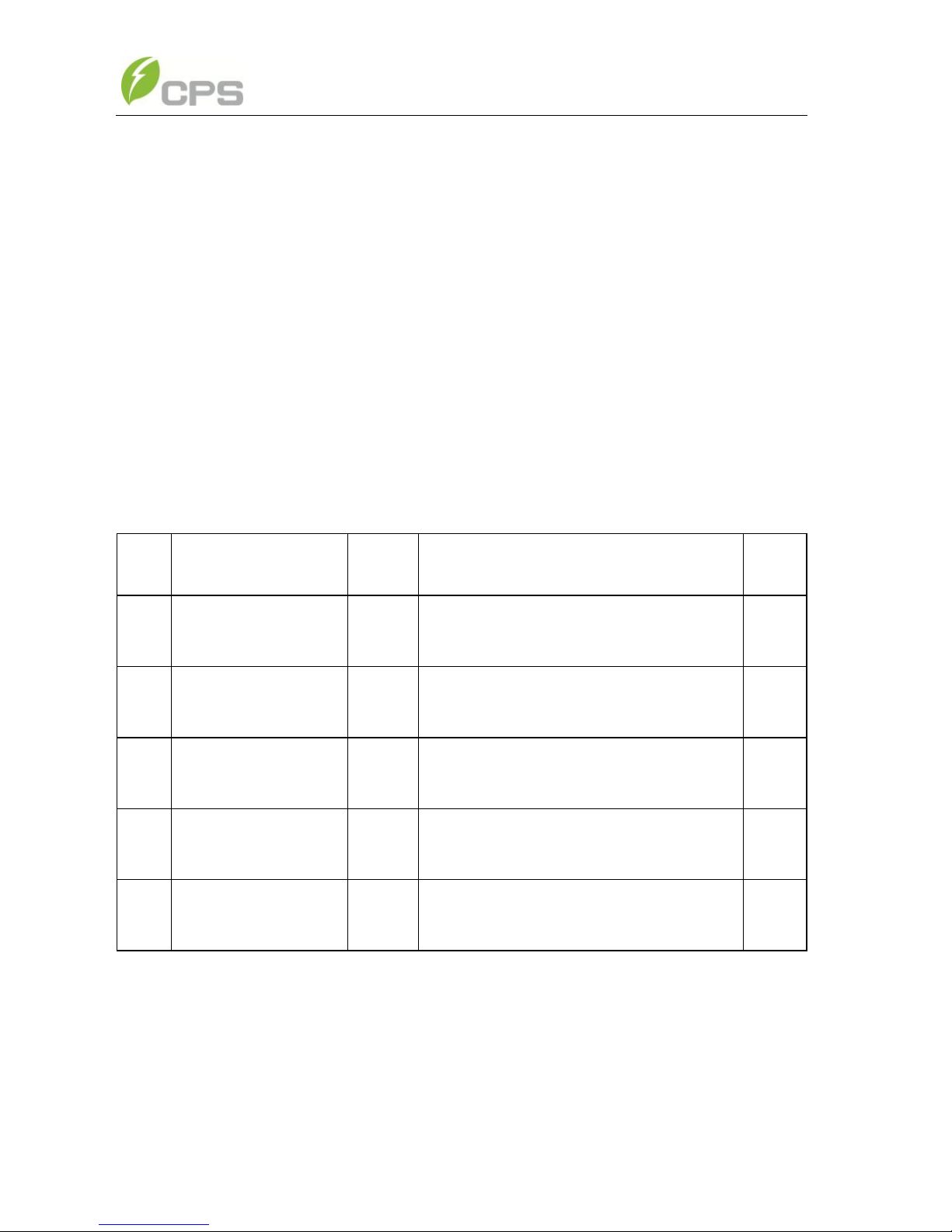
2.5 Appearance and Main items Description..........................................8
2.6 Anti-islanding Detection ..................................................................9
2.7 DC Ground fault Protection .............................................................9
2.8 Surge Suppression............................................................................9
2.9 DC Arc-fault Protection ...................................................................9
Chapter 3 Installation ..........................................................................................10
3.1 Recommendations before Installation............................................13
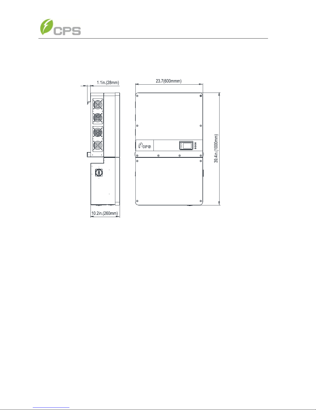
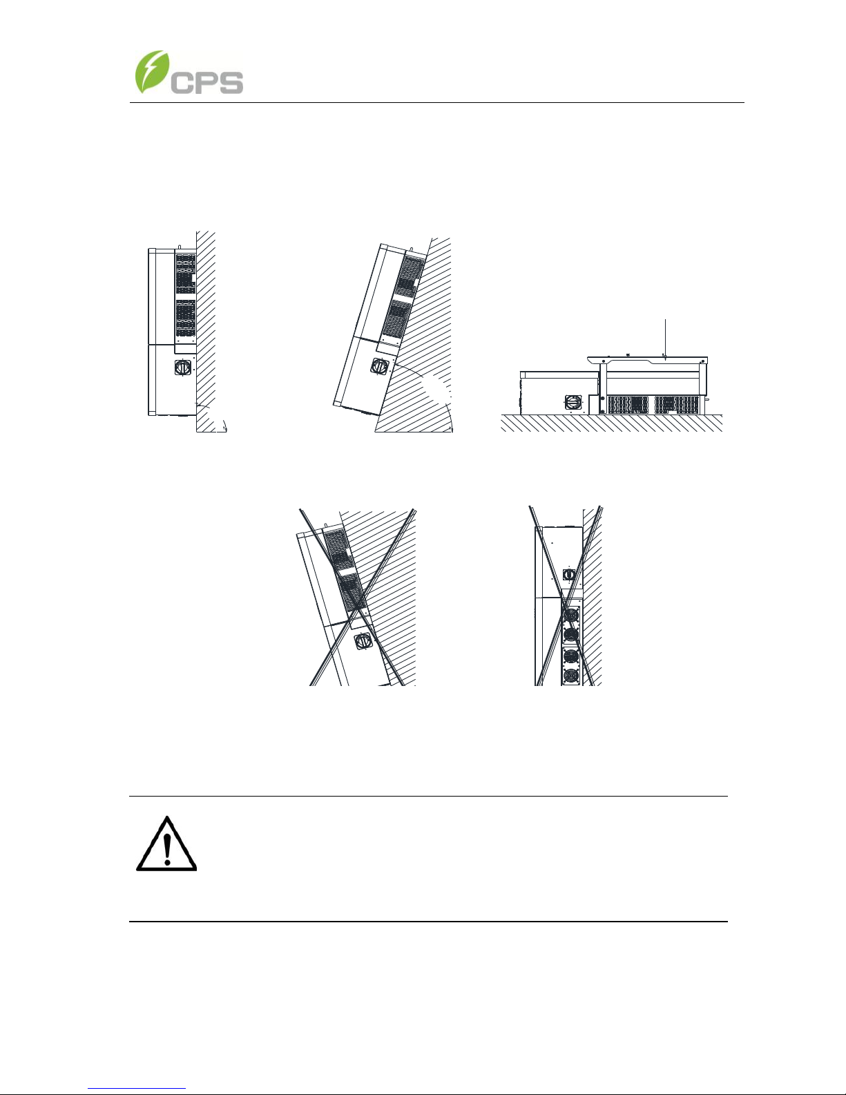
3.2 Mechanical Installation..................................................................14
3.3 Electrical Installation .....................................................................26
3.3.1 Removing/Replacing the Wiring Box Cover:..............................26
3.3.2 DC Connection............................................................................33
3.3.3 AC and Ground Connection........................................................45
3.3.4 Communication Connection........................................................53
Chapter 4 Commissioning....................................................................................60
4.1 Commissioning Checklist ..............................................................60
4.1.1 Mechanical Installation...............................................................60
4.1.2 Cable Connections ......................................................................60
4.1.3 Electrical Check..........................................................................60
4.2 Commissioning Steps.....................................................................61
Chapter 5 User Interface......................................................................................66
5.1 Description of LCD Panel..............................................................66
5.2 Operation State...............................................................................68
5.3 Interface Types...............................................................................69
5.4 Main Menu.....................................................................................71
5.4.1 Operation Information.................................................................72
5.4.2 Setting.........................................................................................73
5.4.3 Power ON/OFF...........................................................................97
5.4.4 History ........................................................................................98
5.4.5 Device Information .....................................................................99

Chapter 6 Operation.............................................................................................100
6.1 Start-Up..........................................................................................100
6.2 Shut-Down.....................................................................................100
6.3 Operation Mode .............................................................................101
6.4 Grid-tied Power Generation ...........................................................103
Chapter 7 Maintenance and De-installation.......................................................104
7.1 Fault Shutdown and Troubleshooting.............................................104
7.1.1 LED Fault and Troubleshooting..................................................104
7.1.2 LCD Fault and Troubleshooting..................................................105
7.2 Product Maintenance......................................................................114
7.2.1 Check Electrical Connections .....................................................114
7.2.2 Clean the Air Vent Filter..............................................................114
7.2.3 Replace the Cooling Fans............................................................114
7.2.4 Replace the Inverter ....................................................................116
7.3 De-installing the Inverter ...............................................................117
Chapter 8 Technical Data.....................................................................................119
Chapter 9 Limited Warranty...............................................................................124

1
Before You Start…
This Installation and Operation manual contains important information, safety
guidelines, detailed planning and setup information for installation, as well as
information about configuring, operating and troubleshooting the
CPS SCA50KTL-DO/US-480 and CPS SCA60KTL-DO/US-480
3-Phase String Inverters. Be sure to read this manual carefully before
operating or servicing the inverters.
Thank you for choosing a CPS 3-Phase String Inverter. These PV Inverters
are high performance and highly reliable products specifically designed for the
North American Solar market.
Installation, commissioning, troubleshooting, and maintenance of the inverter
must only be performed by qualified personnel. If you encounter any
problems during installation or operation of this unit, first check the user
manual before contacting your local dealer or supplier. This user manual is
applicable for the following models:
CPS SCA50KTL-DO/US-480 and CPS SCA60KTL-DO/US-480
Instructions inside this user manual will help you solve most installation and
operation difficulties. Contact your local supplier if the problem still exists.
Please keep this user manual on hand for quick reference.

2
Chapter 1 IMPORTANT SAFETY INSTRUCTIONS
(SAVE THESE INSTRUCTIONS)
Please read this user manual carefully before installation of the product.
CPS reserves the right to refuse warranty claims for equipment damage if the
user fails to install the product according to the instructions in this manual.
Warnings and symbols in this document
DANGER:
DANGER indicates a hazardous situation which, if not avoided, will
result in death or serious injury.
WARNING:
WARNING indicates a hazardous situation which, if not avoided,
could result in death or serious injury.
CAUTION:
CAUTION indicates a hazardous situation which, if not avoided,
could result in minor or moderate injury.
NOTICE:
NOTICE indicates a hazardous situation which, if not avoided, could
result in the inverter working abnormally or property loss.
INSTRUCTION:
INSTRUCTION indicates important supplementary information or
provides skills or tips that can be used to help you solve a problem or
save you time.

3
Markings on the product
HIGH VOLTAGE:
This inverter operates with high voltages. All work on the inverter
must only be performed as described in this document.
HOT SURFACE:
The inverter is designed to meet international safety standards, but
surfaces can become hot during operation. Do not touch the heat
sink or peripheral surfaces during or shortly after operation.
EARTH GROUND:
This symbol marks the location of the grounding terminal, which
must be securely connected to Ground through the AC EGC
(Equipment Grounding Conductor) to ensure operational safety.
WARNING:
All the installation and wiring connections should only be performed by
qualified technical personnel. Disconnect the inverter from the PV
modules and the AC grid before maintaining or servicing the
equipment.
Risk of electric shock and fire. Use only with PV modules that have
a maximum system voltage of rating of 1000V or higher.
Electric shock Hazard. The DC conductors of this photovoltaic
system are normally ungrounded but will become intermittently
grounded without indication when the inverter performs the PV array
isolation measurement.
Shock Hazard. The inverter is energized from both AC and DC
sources. Disconnect all sources before servicing.
For continued protection against risk of fire, replace only with same
type and ratings of fuse.

4
DANGER:
Disconnect the inverter from the AC grid and PV modules before
removing covers or opening the equipment. Ensure hazardous high
voltage and energy inside the inverter has been discharged prior to
servicing. Wait at least 5 minutes after disconnecting from the DC
and AC sources before servicing or maintaining the inverter.
NOTICE:
The inverters are designed to only interconnect with an AC power
source as part of the public electric utility grid. Do not connect the AC
output of the inverters directly to any private electric utility power
equipment.
CAUTION:
CPS SCA50KTL-DO/US-480 and SCA60KTL-DO/US-480 inverters
weigh approximately 56kg (123.5 pounds).The wirebox portion
weighs approximately 15kg (33 pounds).
Ensure the mounting bracket is properly installed before hanging the
inverter and wirebox on the bracket. A team of two is recommended
to lift and place the inverter and wirebox into position.
INSTRUCTION:
Please check with your local electric utility supply company before
selecting a grid standard. If the inverter is operated with an incorrect
grid standard, the electric utility supply company may cancel the
interconnection agreement.
Placing the inverter into operation before the overall system complies
with the national codes, rules and safety regulations of the application
is also not permitted.

5
Chapter 2 Overview
2.1 Inverter for grid-tied PV systems
CPS SCA50KTL-DO/US-480 and SCA60KTL-DO/US-480 3-Phase String
Inverters are designed for use with carport, commercial rooftop, and large utility
scale PV grid-tied systems. The system is generally made up of PV modules, a
3-Phase String Inverter with a fused combiner/disconnect, and AC power
distribution equipment (Figure 2-1). The inverter converts the available DC energy
from the PV modules to AC power by synchronizing the output current to the same
frequency and phase as the AC grid. All or part of the AC power is supplied to
local loads, and the surplus power is exported to the electric utility grid.
AC Grid
Bidirectional
electric meter
AC power
distribution
equipment
Figure 2-1 Grid-tied PV system
2.2 Product Features
High conversion efficiency: Advanced 3-level conversion topology with
SVPWM; Max. efficiency: 98.8%;CEC efficiency: 98.5%
Grid adaptability: IEEE 1547, Rule 21, and HECO SRDs applicable; Reactive
Power; >0.99 PF (±0.8 adjustable), Remote Active Power Curtailment.
Flexible communication: Supports standard CPS Modbus RS485, SunSpec
Modbus, and TCP/IP communications to ensure compatibility with 3rd party
monitoring and control systems.
Wide DC input voltage range: Operating DC Input Voltage Range:
200-950Vdc; Max DC input voltage: 1000V

6
Long Service Life: Uses thin-film capacitors to extend inverter's service life
3 MPPTs: Multi-channel MPPT (Maximum Power Point Tracker) enable
maximum design flexibility and energy harvest optimization over the life of the
system.
Wirebox option: The wirebox enables fused input of either discrete wiring
using the Standard wirebox, or an optional H4 wirebox with quick-fit connectors
for connection of industry standard cord sets.
High protection degree: Powder coated aluminum NEMA 4X enclosure
meets the demanding needs of both indoor and outdoor use.
Intelligent Integration: Integrated load break rated DC/AC disconnect
switches, and up to 15 fused string inputs eliminate the need for external DC
combiner boxes, simplifying installation.
2.3 Product Protection Functions
Reverse polarity protection of DC input
AC and DC Short circuit protection
Arc-fault detection and circuit interruption
Anti-islanding detection with bi-directional frequency perturbation
DC Input and AC output over-voltage protection
DC Input over-current protection
DC input insulation against ground monitoring
DC injection of AC output
AC output voltage and frequency monitoring
Leakage current against ground monitoring
Internal enclosure temperature monitoring
IGBT power module temperature monitoring

7
2.4 Schematic Diagram and Circuit Design
The basic electrical schematic diagram of CPS SCA50KTL-DO/US-480 and
SCA60KTL-DO/US-480 inverters are shown in Figure 2-2.
The input from PV source circuits passes through surge protection circuitry, DC
EMI wave filters, and independent DC-DC boost circuitry to achieve maximum
power point tracking and boost the voltages to a common DC bus. The inverter
uses line voltage and frequency measurements to synchronize to the grid and
converts the available PV energy to AC power by injecting balanced 3-phase AC
current into the electric utility grid. Any high frequency AC component is
removed by passing through a two-stage relay and EMI wave filter to produce
high quality AC power.
Three level
inverter
L1
L2
L3
N
PV1+
PV1+
PV1+
PV1+
PV1+
PV1-
PV1-
PV1-
PV1-
PV1-
DC
Switch MPPT1
MPPT2
PV1+
PV1-
PV2+
PV2-
AC
Output
PV
Input
PV2+
PV2+
PV2+
PV2+
PV2+
PV2-
PV2-
PV2-
PV2-
PV2-
AFD
AC
Switch
Fuses
MPPT3
PV3+
PV3-
PV3+
PV3+
PV3+
PV3+
PV3+
PV3-
PV3-
PV3-
PV3-
PV3-
DC SPD
DC SPD
DC SPD
Figure 2-2 Schematic Diagram of the CPS SCA50/60KTL-DO/US-480 Inverter

8
2.5 Appearance and Main items Description
2
8
9
567
1
3
4
Figure 2-3 Diagram of the CPS SCA50KTL-DO/US-480 and
SCA60KTL-DO/US-480 Inverters
Main items of the Inverter:
1) Main inverter enclosure
2) Inverter wirebox
3) Inverter mounting bracket
4) Cooling fans
5) LED indicator lights
6) User LCD display
7) User Key buttons
8) DC switch: DC power on/off
9) AC switch: AC power on/off

9
2.6 Anti-islanding Detection
The SCA50KTL-DO/US-480 and SCA60KTL-DO/US-480 inverters include
Unintentional Islanding detection as required by UL1741/IEEE1547. The inverter
will continuously make bi-directional perturbations to the frequency of the output
current by injecting a small amount of reactive power in order to detect a
possible islanding condition. If the grid is stable, these small perturbations will
have negligible effects on the system voltage frequency. However, in an islanded
condition the changes in reactive power will force the frequency of the system
voltage to deviate significantly, which will trigger the inverter to cease operation
and disconnect from the grid.
2.7 DC Ground fault Protection
The inverters include residual current detection as part of the DC ground fault
detection method required by UL1741. If there is a ground fault in the PV array,
the ground fault detection circuitry will detect leakage current and trigger an
alarm. The inverter will cease operation if the leakage current exceeds 500mA.
2.8 Surge Suppression
Standard Waveform Peak Values
Surge Category
Ring Wave
Combination Wave
B
6kV/0.5kA
6kV/3kA
"Standard 1.2/50 μs - 8/20 us Combination Wave"
"Standard 0.5 μs - 100 kHz Ring Wave"
2.9 DC Arc-fault Protection
The inverters include DC Arc-fault detection compliant with UL 1699B. The
inverter will detect electrical noise that is indicative of a DC series arc. Upon
detection of an acr-fault, the inverter will cease operation.

10
Chapter 3 Installation
This chapter describes the planning and installation procedures for the
SCA50KTL-DO/US-480 and SCA 60KTL-DO/US-480 inverters. Please read
carefully and install the products following the step-by-step instructions.
The inverter and other main items are shipped in two separate packages,
consisting of A.) the main inverter enclosure and B.) the wirebox, mounting
bracket, user manual, and accessory kit. Before installation, please check that
the following items are included in the packages:
Table 3-1 Main Items
No.
Item
Q’ty
Note
Box
(1)
Main enclosure of
the PV inverter
1
A
(2)
Wiring box of the
PV inverter
1
B
(3)
Mounting bracket
1
Bracket upon which the PV inverter
is hung and mounted
B
(4)
User manual
1
PV inverter installation and
operation manual
B
(5)
Accessory kit
1
Kit contains all necessary hardware
and accessories for installation
B

11
Note that the items in the Accessory Kits vary between the Standard
wirebox and H4 wirebox, the items listed below:
Table 3-2 Accessory Kit (Standard wirebox)
No.
Item
Q’ty
Note
(1)
M8 Expansion Anchors
8
For attaching the mounting bracket to
a concrete wall or surface
(2)
M8×25mm machine
bolts with integrated
lock washer
8
Used with M8 expansion anchors
(3)
M6 X18mm Phillips
screw
11
4 for securing the wiring box to the
main enclosure; 6 for securing the
inverter to the mounting bracket; 1 for
the External Ground connection
(4)
5 pin PCB connector
plug
1
For the RS485 communication
(5)
#10 AWG Wire ferrules
33
30 for PV conductors, includes 3
spares
(6)
M8 Nut
4
For the AC terminal block
(7)
M8 Flat washer
4
For the AC terminal block
(8)
M8 Spring washer
4
For the AC terminal block

12
Table 3-3 Accessory Kit (H4 wirebox)
No.
Item
Q’ty
Note
(1)
M8 Expansion Anchors
8
For attaching the mounting bracket to
concrete wall or surface
(2)
M8×25mm machine
bolts with integrated
lock washer
8
Used with M8 expansion anchors
(3)
M6 X18mm Phillips
screw
11
4 for securing the wiring box to the
main enclosure; 6 for securing the
inverter to the mounting bracket; 1 for
the External Ground connection
(4)
5 pin PCB connector
plug
1
For the RS485 communication
(5)
PV Connector (Male)
15
For the PV input. #10 AWG contact
(6)
PV Connector (Female)
15
For the PV input. #10 AWG contact
(7)
Tool for PV Connector
1
For PV Connector
(8)
M8 Nut
4
For the AC terminal block
(9)
M8 Flat washer
4
For the AC terminal block
(10)
M8 Spring washer
4
For the AC terminal block
INSTRUCTION:
The items in the Accessory Kit Table 3-2 and Table 3-3 above are for
the standard configuration. The accessories provided may vary if
optional parts are purchased.

13
3.1 Recommendations before Installation
See Chapter 8, Technical Data for specification ranges and limits
Check that the inverter environmental specifications (protection degree,
operating temperature range, humidity and altitude, etc) meet the
requirements of the specific project location.
Make sure that the electric utility grid voltage is within range for the grid
standard chosen.
Ensure that the local electric utility grid authority has granted permission to
connect to the grid.
Installation personnel must be qualified electricians or those who have
received professional training.
Wear and use proper PPE (personal protective equipment) during
installation.
Sufficient space according to Figure 3-3 and 3-4 must be provided to allow
the inverter cooling system to operate normally.
Install the inverter away from flammable and explosive substances.
Avoid installing the inverter in locations that exceed the temperature limits
specified for the inverter to prevent undesirable power loss.
Do not install the inverter near an electromagnetic source which can
compromise the normal operation of electronic equipment.
NOTICE:
The allowable ambient temperature range for the
SCA50KTL-DO/US-480 and SCA 60KTL-DO/US-480 inverters is
defined based on the following conditions;
Condition 1: -40C to 70C, Inverter not installed, and in storage (in
packaging or unpackaged).
Condition 2: -30C to 60C, Inverter installed, connected to electric
utility grid and operating during daylight hours.
Condition 3: No low temp limit to 70C, Inverter installed, connected
to electric utility grid but non-operating (daylight or nighttime hours).

14
3.2 Mechanical Installation
1) Dimensions
Figure 3-1 Dimensions of CPS SCA50/60KTL-DO/US-480 Inverter
2) Installation Method (see Figure 3-2):
Ensure that the mounting structure (wall, rack, roof, etc) is suitable to support
the weight of the inverter. Follow the mounting guidelines below:
(a) If the location permits, install the inverter vertically.
(b) If the inverter cannot be mounted vertically, it may be tilted backward to
horizontal.
(c) Do not mount the inverter leaning forward.
(d) Do not mount the inverter upside down.

15
Figure 3-2 Inverter Mounting Options
NOTICE:
When the inverter is mounted backwards by ≤30° in an outdoor
environment, the CPS shade cover accessory must be installed on
the inverter to avoid direct sunlight.
90¡ ã
15~90¡ ã
(a) (b)
(c) (d)
Shade cover

16
3) Installation Space Requirement (see Figure 3-3):
The distances between the inverters or the surrounding objects should meet
the following conditions:
≥300mm
(11.8in.)
≥300mm
(11.8in.)
≥500mm
(19.7in.)
=600mm
(23.6in.)
Note:This dimension can be modified
according to installation requirements.
Figure 3-3 Inverter Wall Mounting Dimensions
NOTICE:
The spacing between two adjacently mounted inverters must be
≥500mm (19.7 inches). Spacing should be enlarged for installation
locations with ambient temperature higher than 45°C. Ensure that
the air space around the inverter is well ventilated. The spacing
below the inverter is intended to ensure the LCD and Keypad height
are well positioned for the user, and may be descreased, however
consideration must be taken for locations known to flood or have
seasonal snow build up.
INSTRUCTION:
If the inverter is installed on Unistrut or the array racking (instead of
solid wall), the space from the bottom of one inverter to the top of the
inverter below may be as small as 100mm (3.9in). The spacing below
may be as small as 300mm (11.8in).
This manual suits for next models
1
Table of contents
Other Chint Power Inverter manuals

Chint Power
Chint Power CPS PSW1.5M-1500V User manual

Chint Power
Chint Power CPS SCE4KTL-O/US User manual

Chint Power
Chint Power CPS SCH Series User manual

Chint Power
Chint Power CPS SCE4 User manual

Chint Power
Chint Power CPS SCA25KTL-DO User manual

Chint Power
Chint Power CPS Series User manual

Chint Power
Chint Power CPS SC2.8KTL User manual