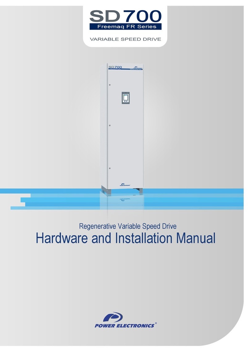
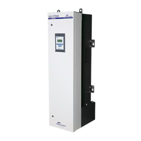
Power Electronics SD700 Series Parts list manual

Touch-Graphic Display
Getting Started Manual


Getting Started Manual
Touch-Graphic Display
Edition: June 2008
SD70IM02BI Rev. B

SD700 – TOUCH-GRAPHIC DISPLAY POWER ELECTRONICS
2

POWER ELECTRONICS SD700 – TOUCH-GRAPHIC DISPLAY
3
E
NGLISH
SAFETY SYMBOLS
Always follow safety instructions to prevent accidents and potential hazards from occurring.
Edition of June 2008
This publication could present technical imprecision or misprints. The information here included will be
periodically modified and updated, and all those modifications will be incorporated in later editions.
To consult the most updated information of this product you might access through our website
www.power-electronics.com where the latest version of this manual can be downloaded.
Revisions
Date Revision Description
26 / 09 / 2007 A Update to Software version SW 1.3 (08)
11 / 06 / 2008 B Adaptation to new name SD700
WARNING This symbol means improper operation may results in serious personal
injury or death.
CAUTION
Identifies shock hazards under certain conditions. Particular attention should
be given because dangerous voltage may be present. Maintenance
operation should be done by qualified personnel.
Identifies potential hazards under certain conditions. Read the message and
follow the instructions carefully.
Identifies shock hazards under certain conditions. Particular attention should
be given because dangerous voltage may be present.

SD700 – TOUCH-GRAPHIC DISPLAY POWER ELECTRONICS
4

POWER ELECTRONICS SD700 – TOUCH-GRAPHIC DISPLAY
INDEX 5
E
NGLISH
INDEX
SAFETY INSTRUCTIONS........................................................................................................... 7
1. DESCRIPTION..................................................................................................................... 11
1.1. Status LEDs ............................................................................................................... 13
1.2. Control Keys .............................................................................................................. 13
1.3. LCD Screen ............................................................................................................... 14
1.4. Pen Interfacing........................................................................................................... 14
2. APPLICATION MANAGEMENT .......................................................................................... 15
2.1. Graphic User Interface ............................................................................................... 15
2.2. Navigation Structure................................................................................................... 18
2.3. Visualization Area Menus........................................................................................... 20
2.4. Parameter Setting ...................................................................................................... 25
2.5. Parameters Lock........................................................................................................ 27
2.6. Application Assistant (Help System) .......................................................................... 31
2.7. System Menu ............................................................................................................. 32
2.8. Fault Visualization...................................................................................................... 39
3. SMS SERVICE..................................................................................................................... 40
3.1. Message Management............................................................................................... 41
3.2. User Management...................................................................................................... 44
3.3. SMS Service Configuration ........................................................................................ 44
3.4. SMS Service Use. Examples ..................................................................................... 55

SD700 – TOUCH-GRAPHIC DISPLAY POWER ELECTRONICS
6 INDEX

POWER ELECTRONICS SD700 – TOUCH-GRAPHIC DISPLAY
SAFETY INSTRUCTIONS 7
E
NGLISH
SAFETY INSTRUCTIONS
IMPORTANT!
Read this manual carefully to maximise the performance of this product and to ensure its safe use.
In this manual, safety messages are classified as follows:
WARNING
Do not remove the cover of the drive while the power is applied or the unit is in operation.
Otherwise electric shock could occur.
Do not run the drive with the front cover removed.
Otherwise you may get an electric shock due to the high voltage terminals or exposure of charged
capacitors.
Do not remove the cover except for periodic inspections or wiring, even if the input power is not
applied.
Otherwise you may access the charged circuits and get an electric shock.
Wiring and periodic inspections should be performed at least 10 minutes after disconnecting the
input power and after checking the DC Link voltage is discharged with a meter (below 30VDC).
Otherwise you may get an electric shock.
Operate the switches with dry hands.
Otherwise you may get an electric shock.
Do not use cables with damaged insulation.
Otherwise you may get an electric shock.
Do not subject the cables to abrasions, excessive stress, heavy loads or pinching.
Otherwise, you may get an electric shock.
CAUTION
Install the drive on a non-flammable surface. Do not place flammable material nearby.
Otherwise fire could occur.
Disconnect the input power if the drive gets damaged.
Otherwise it could result in a secondary accident or fire.
After the input power is applied or removed, the drive will remain hot for a couple of minutes.
Touching hot parts may result in skin burns.
Do not apply power to a damaged drive or to a drive with parts missing even if the installation is
complete.
Otherwise you may get an electric shock.
Do not allow lint, paper, wood chips, dust, metallic chips or other foreign matter into the drive.
Otherwise fire or accident could occur.

SD700 – TOUCH-GRAPHIC DISPLAY POWER ELECTRONICS
8 SAFETY INSTRUCTIONS
WARNINGS
RECEPTION
The equipment is carefully tested and perfectly packed before leaving the factory.
In the even of transport damage, please ensure that you notify the transport agency and
POWER ELECTRONICS: 902 40 20 70 (International +34 96 136 65 57) or your nearest agent,
within 24hrs from receipt of the goods.
UNPACKING
Make sure model and serial number of the equipment are the same on the box, delivery note
and unit.
Each graphic display is supplied with a getting started manual.
SAFETY
Before operating the drive by using the graphic display, read this manual thoroughly to gain and
understanding of the unit. If any doubt exists then please contact POWER ELECTRONICS, (902
40 20 70 / +34 96 136 65 57) or your nearest agent.
Wear safety glasses when operating the drive with power applied and the front cover is
removed.
Handle the drive with care according to its weight.
Install the drive according to the instructions within this manual.
Do not place heavy objects on the drive.
Ensure that the mounting orientation of the drive is correct.
Do not drop the drive or subject it to impact.
The SD700 drives and the graphic display contain static sensitive printed circuits boards. Use
static safety procedures when handling these boards.
Avoid installing the drive in conditions that differ from those described in the Technical
Characteristics section in ‘Getting Started Manual’ for SD700.
CONNECTION PRECAUTIONS
To ensure correct operation of the drive it is recommended to use a SCREENED CABLE for the
control wiring.
For EMERGENCY STOP, make sure supply circuitry is open.
Do not disconnect motor cables if input power supply remains connected. The internal circuits of
the SD700 Series will be damaged if the incoming power is connected and applied to output
terminals (U, V, W).
It is not recommended to use a 3-wire cable for long distances. Due to increased leakage
capacitance between conductors, over-current protective feature may not operate correctly.
Do not use power factor correction capacitors, surge suppressors, or RFI filters on the output
side of the drive. Doing so may damage these components.
Always check whether the DC Link LED is OFF before wiring terminals. The capacitors may hold
high-voltage even after the input power is disconnected. Use caution to prevent the possibility of
personal injury.
POWER ELECTRONICS SD700 – TOUCH-GRAPHIC DISPLAY
SAFETY INSTRUCTIONS 9
E
NGLISH
TRIAL RUN
Verify all parameters before operating the drive. Alteration of parameters may be required
depending on application and load.
Always apply voltage and current signals to each terminal that are within levels indicated within
the manual. Otherwise, damage to the drive may result.
OPERATION PRECAUTIONS
When the Auto Restart function is enabled, keep clear of driven equipment, as the motor will
restart suddenly after a fault is reset.
The “STOP / RESET” key on the keypad is active only if the appropriate function setting has
been made. For this reason, install a separate EMERGENCY STOP push button that can be
operated at the equipment.
If a fault reset is made with the reference signal still present then a restart will occur. Verify that it
is permissible for this to happen, otherwise an accident may occur.
Do not modify or alter anything within the drive.
Before programming or operating the SD700 Series, initialise all parameters back to factory
default values.
EARTH CONNECTION
The drive is a high frequency switching device and leakage current may flow. Ground the drive
to avoid electrical shock. Use caution to prevent the possibility of personal injury.
Connect only to the dedicated ground terminal of the drive. Do not use the case or the chassis
screw for grounding.
When installing, grounding wire should be connected first and removed last.
The earth cable must have a minimal cross sectional area that meets local country electrical
regulations.
Motor ground must be connected to the drive ground terminal and not to the installation’s
ground. We recommend that the section of the ground connection cable should be equal or
higher than the active conductor.
Installation ground must be connected to the drive ground terminal.

SD700 – TOUCH-GRAPHIC DISPLAY POWER ELECTRONICS
10 SAFETY INSTRUCTIONS

POWER ELECTRONICS SD700 – TOUCH-GRAPHIC DISPLAY
DESCRIPTION 11
E
NGLISH
1. DESCRIPTION
The touch-graphic display provides a much more intuitive data presentation, an easy navigation through
the control parameters and allows saving thousands of customized configurations defined by the user.
Some of the outstanding characteristics of the touch-graphic display are:
TFT-LCD Touch screen of 3,5 inches and 240x320 pixels
Customized visualization by the user
GSM and GPRS communication (SMS Service)
System help built-in
Fault Register (Logs)
Language selection

SD700 – TOUCH-GRAPHIC DISPLAY POWER ELECTRONICS
12 DESCRIPTION
The touch-graphic display for the SD700 is a removable display unit for its remote installation, as the
following figure shows:
Figure 1.1 Touch-Graphic Display Unit
There are three indicator leds integrated on the display that supply information about the drive operational
status. Also there are a LCD screen of 3,5” and two control keys to Start / Stop the drive.
Additionally, there is a pen on the right upper corner of the display unit that is used to access to the
different screens and to adjust all of the parameters of the drive that appear in the display. This is possible
by only touching over the LCD screen.

POWER ELECTRONICS SD700 – TOUCH-GRAPHIC DISPLAY
DESCRIPTION 13
E
NGLISH
1.1. Status LEDs
Leds offer an easy method of identifying if the SD700 is powered up, if the drive is supplying output
voltage, or if the drive has tripped.
Led ON: Yellow colour. When it is lit, indicates equipment is powered up.
Led RUN: Green colour. When it is lit, indicates the motor is powered by the SD700.
Led FAULT: Red colour. When it is blinking, indicates the equipment is in fault status.
Figure 1.2 Status visualization
1.2. Control Keys
There are two keys on the bottom of the display unit that are:
To start the drive from the keypad when the control has been set as local
control (check drive configuration).
To stop the drive from the keypad when the control has been set as local
control. In the case of tripping this key can be used to reset the drive, if local
control is enabled.

SD700 – TOUCH-GRAPHIC DISPLAY POWER ELECTRONICS
14 DESCRIPTION
1.3. LCD Screen
The 3,5” LCD screen of the SD700 is the main visualization and interaction area between the drive
and the user.
In order to interact with the graphic display, the LCD screen should be only touched over with the pen
located on the top-right side of the display unit.
Figure 1.3 LCD screen of the graphic display
1.4. Pen Interfacing
The pen, which is located on the top-right side of the display as it is mentioned above (see figure
1.1), should be only used over the LCD screen. The possible interactions are:
Tap: Just a slight and quick touch over the LCD surface. It is used in many of the interactions with
the GUI (Graphic User Interface). It is used to select items, to set the focus for input text, etc, ...
Tap and Hold: Touch over the LCD screen and keep touching it without moving the pen for more
than 2 seconds. It is used mainly to show up floating menu options.
Sliding: Touch over the LCD screen with the pen moving it around the screen and releasing it. It
is only used to move scroll bars.

POWER ELECTRONICS SD700 – TOUCH-GRAPHIC DISPLAY
APPLICATION MANAGEMENT 15
E
NGLISH
2. APPLICATION MANAGEMENT
2.1. Graphic User Interface
The Graphic User Interface (GUI) is based on:
The main application screen.
Floating menus.
The virtual keyboard.
2.1.1. Main Application Screen
The main application screen is the most important element on the GUI. From it, the drive is
controlled and monitored and it is the starting point of the remaining components of the GUI.
The main application screen is divided in three main areas:
Title Bar
Status Bar
Visualization Area
Figure 2.1 Main Application Screen

SD700 – TOUCH-GRAPHIC DISPLAY POWER ELECTRONICS
16 APPLICATION MANAGEMENT
Title Bar
From left to right (see figure 2.1):
Power icon ‘P’ (Power logo): When the user taps on it, the system menu is shown.
Title: This bar shows the drive rated voltage and current, or the name of the visualized
window depending on the visualized screen. For example, if the initial screen is on the
Visualization Area, this bar will show the drive rated voltage and current, but after accessing
to any menu, the name of which is shown on the Title Bar.
Help button ‘?’: It displays the Help Screen on the Visualization Area.
Back button ‘Í’: To return to the previous screen.
Status Bar
It shows the main status indicators of the drive. From left to right (see figure 2.1):
Drive status: Drive operation status, warnings and trips (see chapters ‘8. STATUS
MESSAGES’ and ’12. FAULT MESSAGES. DESCRIPTIONS AND ACTIONS’ of the SD700
‘Getting Started Manual’ for further information).
Average motor current: It shows the average current consumption by the motor in Amps.
Actual motor speed: It shows the actual motor speed as %. The sign indicates that the motor
rotates in a direction. A positive sign does not only mean that the motor rotates clockwise.
Visualization Area
This area is where the different application menus (configuration and visualization), drive
parameters and configuration options are shown. It is also used for the Help and Fault log
screens (see figure 2.1).
2.1.2. Floating Menus
A Floating Menu is a group of commands related between them arranged in columns. There are
only two types of them in the application:
System menu: Main configuration and system tools menu of the graphic display. It is
accessed just tapping the ‘P’ icon. From this menu the user can:
oManage the parameter files.
oView the fault logs.
oCalibrate the LCD’s Touch Panel
oSet up the language of the display and the SMS service
Figure 2.2 System menu

POWER ELECTRONICS SD700 – TOUCH-GRAPHIC DISPLAY
APPLICATION MANAGEMENT 17
E
NGLISH
Custom Visualization Floating menu: It is accessed doing a tap-and-hold on the Custom
Visualization screen. It manages the variable configuration on the screen. The user can add,
edit or delete variables on the Custom Visualization screen.
Figure 2.3 Custom visualization floating menu
2.1.3. Virtual Keyboard
The virtual keyboard appears automatically whenever the user taps on an edit box. This keyboard
hides itself when the user closes the configuration dialogue window or taps into another non-edit-
box control.
Whenever the user has to write any text or value in any field of any configuration dialogue
window, he will use the virtual keyboard.
The default virtual keyboard which always appears when tapping on an edit box is shown in the
next figure:
Figure 2.4 Default virtual keyboard

SD700 – TOUCH-GRAPHIC DISPLAY POWER ELECTRONICS
18 APPLICATION MANAGEMENT
Additionally, the user can write capital letters and other symbols by tapping on specific keys of the
default keyboard to access to special keyboards. Next, it is shown the different virtual keyboards
and what keys the user should tap on to access to these keyboards from the default board.
Figure 2.5 Different virtual keyboards
2.2. Navigation Structure
The setting and the visualization of the parameters of the drive is managed through Configuration
and Visualization groups respectively (see section ‘2.3.1. Configuration Group (G) and
Visualization (V) Menus’ for additional information).
Through the Custom Visualization screen, the user can select some specific visualization
parameters of the drive to be visualized (see section ‘2.3.3. Custom Visualization Menu’ for
additional information).
The Big Visualization screen is another customizable screen to visualize two drive visualization
parameters in big format (see section ‘2.3.2. Big Visualization Menu’ for additional information).
2.2.1. Menu Screens
In the menu screens, a group of items appear in form of lists. The user can access to other menu
screen or to a parameter screen by tapping on any of the items.
This allows the user to navigate through the different groups of configuration or visualization
parameters.
Figure 2.6 Example of menu screens
Other manuals for SD700 Series
8
Table of contents
Other Power Electronics Inverter manuals

Power Electronics
Power Electronics SD750 Series User manual

Power Electronics
Power Electronics SD 300 Series Parts list manual

Power Electronics
Power Electronics SD700 Series Mounting instructions

Power Electronics
Power Electronics SD 500 Series Mounting instructions

Power Electronics
Power Electronics SD700 Series User manual

Power Electronics
Power Electronics SD 500 Series User manual

Power Electronics
Power Electronics SD750 Series User manual

Power Electronics
Power Electronics SD 500 Series User manual

Power Electronics
Power Electronics SD700 Series Mounting instructions

Power Electronics
Power Electronics SD 500 Series Parts list manual