Chint Power CPS SCA25KTL-DO User manual

CPS SCA Series Grid-tied PV Inverter
CPS SCA20/25KTL-DO
Installation and Operation Manual
Ver 1.0

SHANGHAI CHINT POWER SYSTEMS CO., LTD.
Web: www.chintpower.com/en
Email: [email protected]
Service Hotline: +86-21-37791222-6300
Address: Building 4, No. 3255, Sixian Road,
Songjiang District, Shanghai, China
Zip Code: 201614
SHANGHAI CHINT POWER SYSTEMS CO., LTD. All rights reserved.
Specifications and designs included in this manual are subject to change without notice.
CHINT POWER 2013/11-MKT PN: 9.0020.0111A0

Table of Contents
Before You Start… ...................................................................................1
Chapter 1 IMPORTANT SAFETY INSTRUCTIONS .................................2
Chapter 2 Overview .................................................................................6
2.1 Inverter for grid-tied PV systems................................................6
2.2 Product features.........................................................................6
2.3 Product protection functions.......................................................7
2.4 Circuit structure design...............................................................7
2.5 Appearance Description.............................................................8
Chapter 3 Installation ..............................................................................10
3.1 Basic requirements.....................................................................12
3.2 Mechanical installation...............................................................14
3.3 Electrical installation...................................................................24
3.3.1 DC connection....................................................................27
3.3.2 AC and ground connection .................................................33
3.3.3 Communication connection ................................................38
Chapter 4 Commissioning ......................................................................53
4.1 Commissioning Checklist...........................................................53
4.1.1 Mechanical installation .......................................................53
4.1.2 Cable connections..............................................................53
4.1.3 Electrical check...................................................................53
4.2 Commissioning steps.................................................................53
Chapter 5 User Interface .........................................................................56
5.1 Description of LCD panel ...........................................................56
5.2 Operation state...........................................................................58
5.3 Interface types............................................................................58
5.4 Menu functions...........................................................................60
5.4.1 Operation information.........................................................61

5.4.2 Alarm..................................................................................62
5.4.3 History................................................................................62
5.4.4 System configuration..........................................................64
5.4.5 Power dispatch...................................................................66
5.4.6 AutoTest .............................................................................67
5.4.7 System protection parameters setup..................................69
5.4.8 System control parameters ................................................71
Chapter 6 Operation................................................................................80
6.1 Start-up......................................................................................80
6.2 Shut-down..................................................................................80
6.3 Operation mode.........................................................................80
6.4 Grid-tied power generation ........................................................82
Chapter 7 Maintenance and De-installation..........................................84
7.1 Fault shut down and troubleshooting.........................................84
7.1.1 LED fault and troubleshooting............................................84
7.1.2 LCD fault and troubleshooting............................................84
7.2 Product maintenance.................................................................92
7.2.1 Check the electrical connection..........................................92
7.2.2 Clean the air vent filter .......................................................92
7.2.3 Replace cooling fans..........................................................92
7.2.4 Replace the inverter...........................................................95
7.3 De-installing the inverter ............................................................97
Chapter 8 Technical Data........................................................................98
Chapter 9 Quality Assurance..................................................................102
9.1 Warranty ....................................................................................102
9.2 Disclaimer..................................................................................102
9.3 Quality clause (Warranty clause)...............................................103
Chapter 10 Disposal................................................................................104
Appendix: Instruction of inverter selection ..........................................105

1
Before You Start…
This manual contains important information regarding installation and safe
operation of this unit. Be sure to read this manual carefully before using.
Thank you for choosing this Grid-tied PV Inverter. This PV Inverter is a highly
reliable product due to its innovative design and high quality control. Such an
Inverter is used in high demand, grid-tied PV systems.
If you encounter any problems during installation or operation of this unit, first
check the user manual before contacting your local dealer or supplier. This
user manual is applicable for the following 2 models: CPS SCA20KTL-DO and
CPS SCA25KTL-DO.
Instructions inside this user manual will help you solve most installation and
operation difficulties. Contact your local supplier if the problem still exists.
Please keep this user manual on hand for quick reference.

2
Chapter 1 IMPORTANT SAFETY INSTRUCTIONS
(SAVE THESE INSTRUCTIONS)
Please read this user manual carefully before product installation. CPS
reserves the right to refuse warranty claims for equipment damage if the user
fails to install the equipment according to the instructions in this manual.
Warnings and symbols in this document
DANGER:
DANGER indicates a hazardous situation which, if not avoided, will
result in death or serious injury.
WARNING:
WARNING indicates a hazardous situation which, if not avoided,
could result in death or serious injury.
CAUTION:
CAUTION indicates a hazardous situation which, if not avoided,
could result in minor or moderate injury.
NOTICE:
NOTICE indicates a hazardous situation which, if not avoided,
could result in equipment working abnormally or property loss.
INSTRUCTION:
INSTRUCTION indicates important supplementary information or
provides skills or tips that can be used to help you solve a problem
or save you time.

3
Markings on the product
HIGH VOLTAGE:
The product works with high voltages. All work on the
product must only be performed as described in this
document.
HOT SURFACE:
The equipment is designed to meet international
safety standards, but surfaces can become hot
during operation. Do not touch the heat sink or
peripheral surfaces during or shortly after operation.
HAZARD ENERGY:
Caution, risk of electric shock, energy storage timed
discharge.
EARTH GROUND:
This symbol marks the location of grounding
terminal, which must be securely connected to the
earth through the PE (protective earthing) cable to
ensure operational safety.
RoHS MARK:
The inverter is complied with DIRECTIVE
2011/65/EU, on the restriction of the use of certain
hazardous substances in electrical and electronic
equipment.
CERTIFICATION MARK:
The inverter is approved by the CE certification.

4
WARNING:
All the installation and wiring connections should be performed only
by qualified technical personnel. Disconnect the inverter from PV
modules and the Power Grid before maintaining and operating the
equipment.
DANGER:
Please disconnect the inverter from AC grid and PV modules before
opening the equipment. Make sure hazardous high voltage and
energy inside the equipment has been discharged.
Do not operate or maintain the inverter until at least 5 minutes after
disconnecting all sources from DC and AC sides.
NOTICE:
This inverter is designed to connect AC power only to the public grid.
Do not connect the AC output of this equipment directly to any private
AC power equipment.
NOTICE:
Do not install the inverter under direct sunlight to avoid conversion
efficiency de-rating caused by excessively high temperature.
CAUTION:
CPS SCA20/25KTL-DO series inverter is approx 55 kg (≈122
pounds).
Please ensure the mounting is properly installed before hanging the
the inverter on the bracket.
INSTRUCTION:
Please check with your local electricity supply company before
selecting the grid standard. If the inverter is operated with a wrong

5
grid standard, the electricity supply company may cancel the
operation license.
Putting the inverter into operation before the overall system complies
with the national rules and safety regulation of the application is not
permitted.
6
Chapter 2 Overview
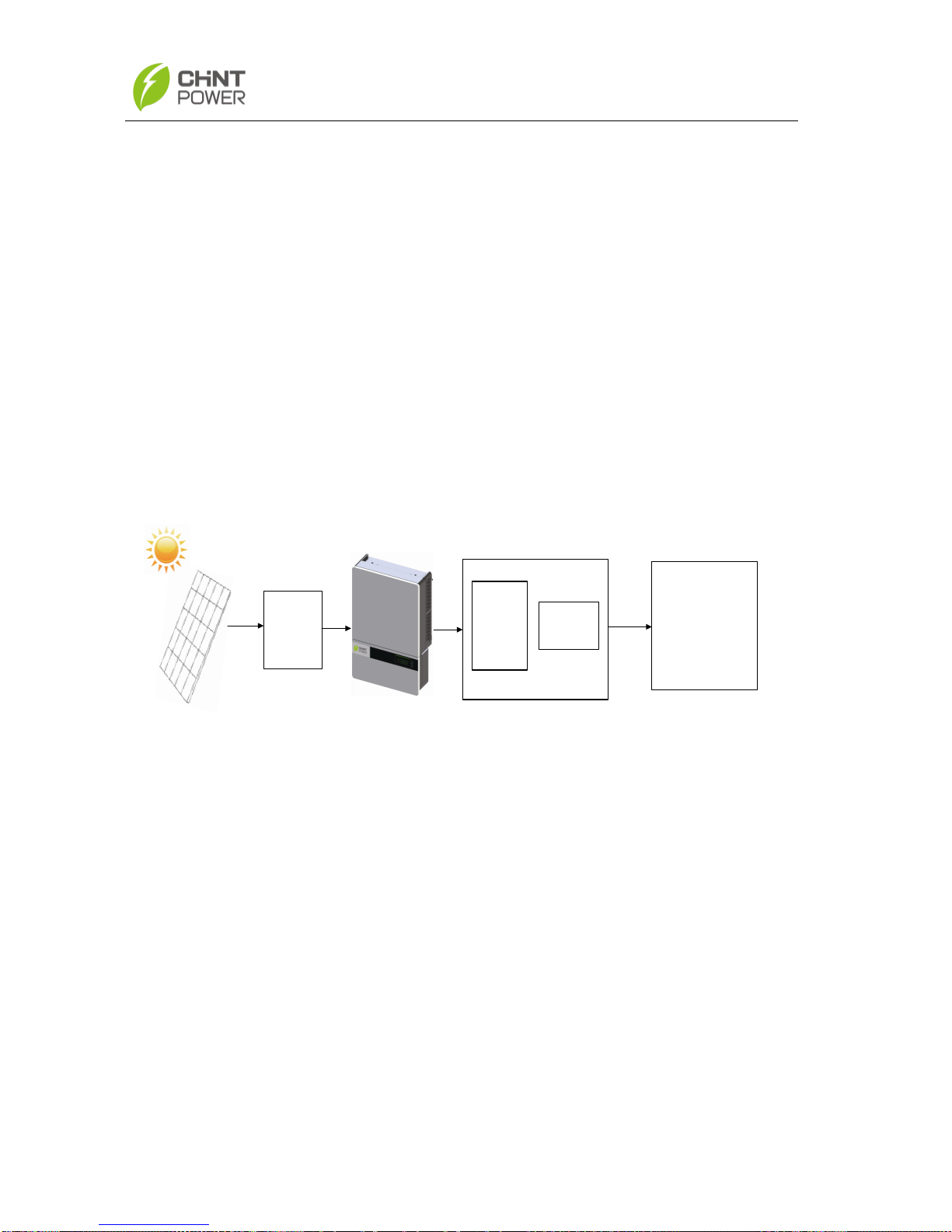
2.1 Inverter for grid-tied PV systems
CPS SCA20/25KTL-DO series inverter is suitable for use with commercial
and large scale PV grid-tied systems. The system is generally made up of PV
modules, DC power distribution equipment, PV inverter and AC power
distribution equipment (Figure 2-1). The inverter converts the DC from PV
modules to AC with the same frequency and phase as the AC grid. All or part
of the AC power is supplied to local loads, and the surplus power is supplied to
the electricity grid.
DC power
distribution
equipments AC Grid
Bidirectional
electric meter
AC power
distribution
equipments
Figure 2-1 Grid-tied PV system
2.2 Product features
High conversion efficiency:Advanced 3-level conversion technology;
Max. efficiency: 98.3%;Euro efficiency: 97.8%
Strong grid adaptability: 7 grid standards applicable; LVRT; Reactive
power adjustable; PF value:±0.8
Flexible communication: Support RS485, ZigBee and Ethernet
communications; Firmware upgrade by USB disk available; Fast and
convenient operation
Wide DC input voltage range:Operating DC Input Voltage Range:
300-900Vdc; Max DC input voltage: 1000V

7
Long service life: Uses thin-film capacitors to extend inverter’s service life
2 MPPTs: Support independent and parallel modes of PV connection
High protection degree: IP65 protection degree meets the needs of both
indoor and outdoor use; Embedded DC switch makes field maintenance
more flexible and safer
2.3 Product protection functions
Polarity reverse protection of DC input
Short circuit protection
DC input insulation against ground monitoring
AC output voltage and frequency monitoring
Leakage current against ground monitoring
Monitoring of DC injection from AC output
Anti-islanding protection
Input and output over-voltage protection
Input over-current protection
Environmental temperature monitoring
Module temperature monitoring
2.4 Circuit structure design
The basic schematic diagram of CPS SCA20/25KTL-DO series inverter is
shown in Figure 2-2.
The input of PV modules passes through surge protection circuitry, DC
EMI wave filter, and the front-end boost circuitry to achieve maximum power
tracking and boost up voltages. The output of the inverter converts the DC
voltage to 3-phase AC voltage. The high frequency AC components are
removed with a wave filter. Then the 3-phase AC voltage is passed through
two-stage relays and EMI wave filter to produce high quality AC power.

8
Three level
inverter
N
L1
L2
L3
PV1+
PV1+
PV1+
PV1+
PV1-
PV1-
PV1-
PV1-
DC
Switch MPPT1
MPPT2
PV1+
PV1-
PV2+
PV2-
AC
Output
PV
Input FUSE Clip
( No FUSE)
PV2+
PV2+
PV2+
PV2+
PV2-
PV2-
PV2-
PV2-
PE
Figure 2-2 Schematic diagram of CPS SCA20/25KTL-DO series inverter
2.5 Appearance Description
5
2
1
67
83
4
4
Figure 2-3 Appearance sketch of CPS SCA20/25KTL-DO series inverter

9
Main items of the inverter:
1) Main housing of the inverter
2) Wiring box of the inverter
3) Mounting bracket
4) External cooling fans
5) LED indication lights
6) LCD display
7) Key buttons
8) DC switch: DC power on/off
10
Chapter 3 Installation
Below is the installation procedure for the inverter. Please read carefully and
install the product step-by-step.
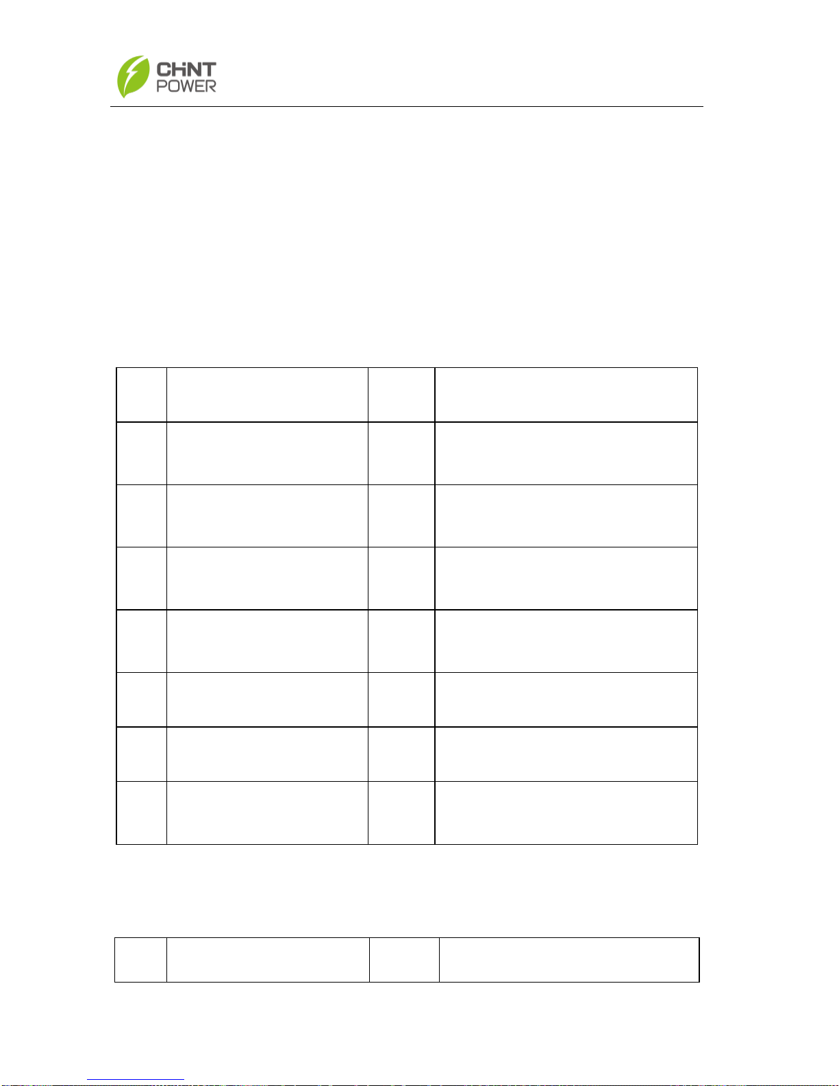
Before installation, please check that the following items are included in
the package:
Table 3-1 Main items
No.
Item
Q’ty
Note
(1)
Main housing of the PV
inverter
1
(2)
Wiring box of the PV
inverter
1
(3)
Mounting bracket
1
Upon which inverter is hung and
mounted onto a wall
(4)
User manual
1
Installation and operation
manual
(5)
Warranty card
1
For maintenance and repair
(6)
Packing list
1
(7)
Accessory kit
1
Contains all necessary
accessories
The (7) Accessory kit contains items listed below:
Table 3-2 Accessories
No.
Item
Q’ty
Note

11
(1)
M8 Expansion tubes
8
For mounting bracket
(2)
M8×25 assembling
bolts
8
For mounting bracket
(3)
M6X12 screw
6
To connect wiring box with main
housing; 2 spare parts
(4)
M5X10 screw
8
For mounting bracket and
inverter, external ground
connection
(5)
M5 flange nut
2
For internal ground stud
connection; 1 spare part
(6)
Lifting eye nut M10
2
For lifting the main housing
(7)
DC input connector
16
8 positive and 8 negative
connectors
(8)
Unlock tool for DC
connector
1
To unlock DC input connectors
(9)
OT type terminal
2
For ground connection
(10)
Pre-insulated end
ferrule
8
For AC output cables and PE
cable, 2 spare parts
(11)
RJ45 connecter
4
For RS485 or Ethernet
communication, 2 spare parts
(12)
Jumper busbar
1
For parallel mode cable
connection (positive pole)
(13)
5 pin connector
1
For RS485 communication
(14)
3 pin connector
1
For dry contact communication

12
3.1 Basic requirements
Check that the product environmental specifications (protection degree,
operating temperature range, humidity and altitude, etc) meet the
requirements of the specific project location.
The Non-isolated inverters shall be provided with installation instructions
that require PV modules that have an IEC 61730 Class A rating.
The inverter has an integrated RCMU, a residual current operated
protective (RCD) or monitoring (RCM) device, which is used for
protection in case of direct or indirect contact with live parts required by
local regulation. Only a RCD or RCM of Type B is allowed to install on the
AC side of the inverter if an external RCMU is needed by customer.
Make sure that the power grid voltage is within normal range.
Permission of grid connection has been granted by the local electricity
supply authority.
Installation personnel must be qualified electricians or people who have
received professional training.
Sufficient convection space to prevent overheating of the inverter;
Install the inverter away from flammable and explosive substances.
Do not expose to direct sunlight to avoid undesirable power derating due
to an increase of internal temperature in the inverter; If unavoidable,
INSTRUCTION:
The items in the accessory kit table above are for the standard
configuration. The accessories may vary if optional parts are
purchased.

13
please install the shading device above the inverter;
Do not install the inverter near the electromagnetic source which can
compromise the normal operation of electronic equipment;
No ice or snow on the inverter;
Figure 3-1 Sketch of installation environment

14
3.2 Mechanical installation
1) Dimensions
Figure 3-2 Dimensions of CPS SCA20/25KTL-DO series inverter

15
2) Installation method (see Figure 3-3):
Make sure that the mounting structure (wall, rack, etc) is suitable to support
the inverter weight. Follow the mounting guidelines below:
(a) If the location permits, install the inverter vertically.
(b) If the inverter cannot be mounted vertically, it may be tilted backward
by no lower than 15 degree from horizontal.
(c) Do NOT mount the inverter leaning forward.
(d) Do NOT mount the inverter in a horizontal position. (<15 degrees)
(e) Do NOT mount the inverter upside down.
(a) (b)
(c) (d) (e)
Figure 3-3 Mount the inverter correctly

16
4) Installation space requirement (see Figure 3-4):
The distances between the inverters or the surrounding objects should
meet the following conditions:
≥300mm
(11.8in.)
≥500mm
(19.7in.)
≥1000mm
(39.4in.)
≥600mm
(23.6in.)
Figure 3-4 Inverter mounting dimensions
5) Mount the inverter onto the bracket
(1) Mark the 8 holes on the bearing surface for mounting the bracket as
shown in Figure 3-5;
NOTICE:
The spacing between two inverters in parallel should be ≥1000mm
(39.4 inches). Ensure that the air space around the inverter is well
ventilated.
Table of contents
Other Chint Power Inverter manuals

Chint Power
Chint Power CPS SC2.8KTL User manual

Chint Power
Chint Power CPS Series User manual

Chint Power
Chint Power CPS PSW1.5M-1500V User manual

Chint Power
Chint Power CPS SCE4 User manual

Chint Power
Chint Power CPS SCE4KTL-O/US User manual

Chint Power
Chint Power CPS SCA50KTL-DO/US-480 User manual

Chint Power
Chint Power CPS SCH Series User manual
Popular Inverter manuals by other brands


Growatt
Growatt MIC 1000TL-X Installation & operation manual

Huawei
Huawei SUN2000 Series Quick installation guide

Tripp Lite
Tripp Lite PowerVerter PV 140 owner's manual

ARX
ARX Centre MIXX owner's manual

Solenso
Solenso SLT Quick installation guide

Generac Power Systems
Generac Power Systems Generator quick guide


