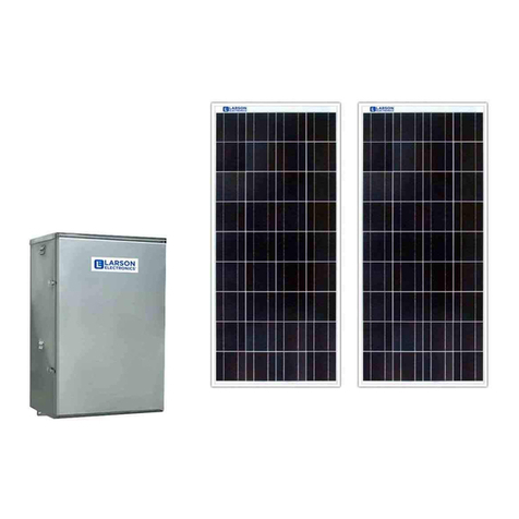
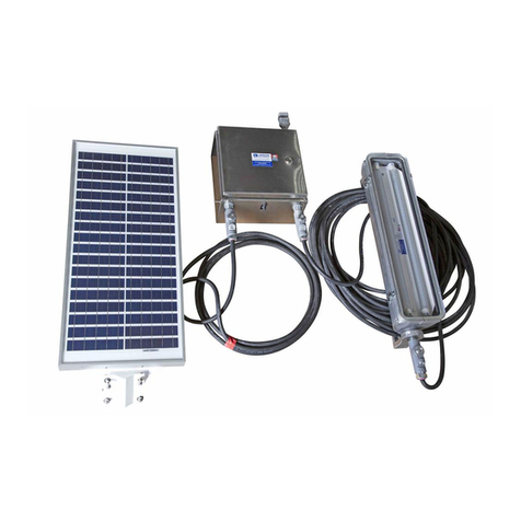
Larson Electronics SPLT IVT-12VDC-1000VA-120VAC Series User manual

SPLT-xx-IVT-12VDC-1000VA-120VAC
Larson Electronics, LLC Phone: (800) 369-6671 Fax: (903) 498-3364 www.larsonelectronics.com
1of 11
Replacement Solar Inverter, 12V DC input, 120V AC Output, 1000 VA
Instruction Manual
Thank you for your purchase of the Larson Electronics SPLT-xx-IVT-12VDC-1000VA-120VAC.
WARNING:
READ CAREFULLY BEFORE INSTALLING FIXTURE. RETAIN THESE INSTRUCTIONS FOR FUTURE REFERENCE.
CRITICAL SAFETY INSTRUCTIONS:
•INSTALLATION SHOULD ONLY BECONDUCTED BY A QUALIFIED ELECTRICIAN IN ACCORDANCE WITH NEC AND ANY
RELEVANT LOCAL BUILDING CODES.
•RISK OFFIRE OR ELECTRIC SHOCK. FIXTURE INSTALLATION REQUIRES KNOWLEDGE OF FIXTURE'S ELECTRICAL
SYSTEMS. IFNOTQUALIFIED, CONTACT A QUALIFIED ELECTRICIAN.
•BE CERTAIN ELECTRICAL POWER IS OFF BEFORE AND DURING INSTALLATION AND MAINTENANCE.
•MAKE SURE THE SUPPLY VOLTAGE IS THE SAME AS THE FIXTURE'S RATED VOLTAGE.
•TO PREVENT WIRING DAMAGE OR ABRASION, DO NOT EXPOSE WIRING TO EDGES OF SHEET METAL OR SHARP
OBJECTS. SUITABLE FOR DAMP LOCATIONS.
IMPORTANT
READ CAREFULLY BEFORE INSTALLING THIS FIXTURE. SAVE THESE INSTRUCTIONS FOR FUTURE
REFERENCE. THE SPLT-xx-IVT-12VDC-1000VA-120VAC MUST BE WIRED IN ACCORDANCE
WITH NATIONAL ELECTRICAL CODE AND ALL APPLICABLE LOCAL CODES. PROPER GROUNDING IS
REQUIRED FOR SAFETY.
WE STRONGLY ENCOURAGE ONLY ALICENSED ELECTRICIAN INSTALL, OPERATE AND MAINTAIN THIS
PRODUCT. IF YOU ARE NOT QUALIFIED OR UNFAMILIAR WITH ANY ASPECT OF THIS INSTRUCTION SHEET,
CONSULT AN ELECTRICIAN. THERE ARE NO SERVICEABLE PARTS INSIDE.
WARNING: MAKE SURE POWER IS TURNED OFF BEFORE STARTING THE
INSTALLATION OR PERFORMING ANY MAINTENANCE.
RISK OF FIRE/ELECTRIC SHOCK –DISCONNECT POWER AT BREAKER BEFORE INSTALLING OR SERVICING.
RISK OF PERSONAL INJURY –FIXTURE MAY BECOME UNSTABLE OR DAMAGED IF NOTINSTALLED PROPERLY.
RISK OF BURN –ALLOW FIXTURE TO COOL BEFORE SERVICING.
Replacement Solar Inverter, 12V DC input, 120V AC Output, 1000 VA

SPLT-xx-IVT-12VDC-1000VA-120VAC
Larson Electronics, LLC Phone: (800) 369-6671 Fax: (903) 498-3364 www.larsonelectronics.com
2 of 11
SOLAR LIGHT TRAILER SCHEDULED MAINTENANCE
SERVICE GUIDE
Battery:
Do monthly check on the battery,tighten the battery cable connections as needed. Wear gloves/eye
protection and use insulated tools.
Clean terminal connections & cables to prevent corrosion. Mix baking soda and distilled water into a paste
and apply with a wire brush. Rinse cleaning residue and dry with a cloth or paper towel.
Keep the top of the batteries clean from dust and debris toavoid creating a current pathway or electrical
leakage across the top of the battery.
Program your voltage set points sothat the battery bank charges at the proper voltage.
Check Battery State of Charge (SoC):
Use a multimeter to keep an eye on how charged your sealed lead-acid batteries are based on the voltage. A
multimeter is equipped with positive and negative probes which allows the meter to get a DC voltage reading
from the battery.
Multimeters give a DCvoltage reading from your batteries.
Look up the battery’s model number tofind its datasheet.It should contain a chart that estimates the battery’s
state of charge based on these voltage readings.
To get the most accurate reading, your batteries should be tested in a resting state. Let your batteries rest for
atleast 2 hours (no charging/discharging) before taking the voltage reading. Attempting to use the multimeter
when batteries are being charged or discharged is going toresult ina higher or lower voltage, depending on
the load.
If your batteries fail to approach 100% SoC even after a full charge cycle, they arelikely defective, damaged,
or have reached the end of their lifespan.
CAUTION:
Under no circumstances should batteries be incinerated, as fire can cause an explosion. Wear approved
gloves when touching electrolyte. Onexposure to skin, flush with water immediately. Ifeye exposure occurs,
flush with water for 15 minutes and consult a physician immediately.

SPLT-xx-IVT-12VDC-1000VA-120VAC
Larson Electronics, LLC Phone: (800) 369-6671 Fax: (903) 498-3364 www.larsonelectronics.com
3 of 11
Solar panels:
During the dryseason or extended periods without rain, itisimportant toclean them manually. It is generally
recommended that you perform solar panel cleaning between two and four times per year. All you really need
is a leaf blower or a quick spray with a garden hose, and your panels will be clean and in top condition.
Before you start in with soap and water, you may want to get rid of large debris. You can do this by using a
dry brush to remove twigs, leaves and other larger items. From there, use your scrub brush and soapy water
to gently start scrubbing your solar panels.
You can use your handheld brush to get too easy to reach panels, and a brush with a long or extendable
handle can get to the ones that are higher up. Be sure that you are not too rough when using the brush
because scrubbing too hard may cause micro-scratches to form on the surface of the panels.
Using a hose with a sprayer, rinse offyour solar panels. Do not use a pressure washer because the force of
the spray can damage the panels. Once your solar panelsare clean but wet, use either a window wiper ora
microfiber cloth on a handle to dry the panels.
Making sure there is not residue on your panelsisan important part ofsolar panel maintenance and cleaning.
Residue can create a film that blocks sunlight and reduces energy production in the same way that dirt can. A
window wiper or microfiber cloth can ensure that your panelsareresidue free.
In winter, you may need to clean your panelsafter a heavy snowfall. If you areusing water to clear the snow
away, make sure it is lukewarm. You can also use a squeegee with a long handle. Just remember, never use
hot water when clearing snow offthe panels. The panels aremade of tempered glass, and the extreme
temperature disparity between hot water and cold panels can crack them.
Whenever you clean the solar panels, also check on the solar connectors to make sure all the cables and
connectors are still making good connection.
Air compressor:
1. Periodically check allelectrical and fittings connections. Clean and tighten as needed.
2. Periodically check allmounting screws. Tighten as needed.
3. Replace Air Filter Element periodically. Replacement frequency depends on operating frequency and
operating environment. For frequent usein dusty environment, we recommend that you replace air filter
element atleast once a month.
4. Regularly clean dust and dirt from compressor cooling fins and motor housing.

SPLT-xx-IVT-12VDC-1000VA-120VAC
Larson Electronics, LLC Phone: (800) 369-6671 Fax: (903) 498-3364 www.larsonelectronics.com
4 of 11
5. Your aircompressor isequipped with a permanently lubricated, maintenance-free motor. Never try to
lubricate the compressor.
6. All repairs should be performed by Manufacturer orManufacturer’s Authorized Service Agencies only.
CAUTION: Never touchthe air compressor or fittings connected to the air compressor, with bare hands during
or immediately after use. The leader hose and fittings connected to leader hose will become very HOT during
and after use. If necessary, wear heat resistant gloves to handle fittings, airline, and leader hose.
Pneumatic mast:
Masts come from the factory pre-lubricated and require no scheduled maintenance under normal operating
conditions. In extremely harsh environmental conditions, maintenance of the mast might be required. Signs
that cleaning and lubrication are needed can be:
• A noticeable gritty film on the exterior surfaces of the mast sections
• rratic extension or retraction of the mast
•Noisy operation of the mast
• ticking of one or more mast sections when mast isextending or retracting
PROCEDURE:
1. Remove top load from the mast. Thiswill allow the sections ofa non-locking mast to more easily be
extended from smallest to largest. See Step 3. On locking masts, the sequence of extension can be
controlled by the locking collars.
2. When a regulator exists in the pneumatic system, reduce its pressure tobetween 5 and 10 PSIG.
NOTE: 10 PSIG should be sufficient pressure to extend all sections ofthe mast without a top load. Ifany
section will not extend with 10 PSIG the mast may require overhaul. Consult the factory.
3. One person operating the air control valve should slowly pressurize the mast just enough to extend the top
mast section.
Another person may need to hold down the larger mast section collars to assure the proper sequence of
extension. Close the air control valve as soon as the mast section is up.

SPLT-xx-IVT-12VDC-1000VA-120VAC
Larson Electronics, LLC Phone: (800) 369-6671 Fax: (903) 498-3364 www.larsonelectronics.com
5 of 11
4. Dampen a rag with a non-abrasive cleanser or solvent such as lacquer thinner to wipe down the extended
mast section. Donot allow the cleaning fluid or solvent torun down inside the collar.
5. Repeat steps 3 and 4 for the nextlarger mast section.
6. Inject approximately 1/2 oz. of Mast Lubricant ora lightweight machine oil into the air holes of the exposed
mast section.
7. Repeat steps 3,4 and 6 for each of the remaining mast sections. The larger diameter sections should be
injected with approximately 1 oz. oflubricant.
8. Lower the mast completely. Allow several minutes for the lubricant tosettle and spread around the wear
ring and seal at the bottom ofeach mast section.
9. Extend the mast againone section at a time in the same sequence (smallest tolargest). Wipe off any
excess lubricant that flows out of the air holes.
Tires:
Check the tires pressure regularly and before transport the solar trailer. Low pressure in tires could cause the
solar trailer tonot level correctly. Fill the tires up with airifthe pressure islow. Replace your tires ifthe tread
worn out.
Trailer’s brake lights &license plate lights:
Check the brake lights, make sure allbrake lights work properly on the trailer before transport. If light does not
turn on, check allwire connections to the light make sure allconnections are good. Iflight still not turn on,
change light bulb.

SPLT-xx-IVT-12VDC-1000VA-120VAC
Larson Electronics, LLC Phone: (800) 369-6671 Fax: (903) 498-3364 www.larsonelectronics.com
6 of 11
TRAILER SCHEDULED MAINTENANCE AND INSPECTIONS
Before Towing Trailer:
Each time you plan to tow your trailer, inspect and service the following items:
•Breakaway Brakes (electric and hydraulic) – Check operation.
•Breakaway Battery – Ensure connections are clean and the battery isfully charged.
•Electric Brakes – Check operation.
•Lighting - Check the brake lights (stop lights, brake lights, turn signals), make sure all brake lights
work properly on the trailer before transport.
•Surge Brakes – Check operation and master cylinder level.
•Shoes and Drums – Adjust.
•Safety Chains and Hooks – Check for wear and damage.
•Coupler and Hitch Ball – Check for cracks, pits, and flats. Replace with ball and coupler hitch having
trailer GVW rating if needed.Grease, and then check locking device and replace when worn.
•Ring and Pintle – Follow the same steps as you would for the Coupler and Hitch Ball. Replace with a
ring and pintle having trailer GVW rating if needed.
•Tires – Check tire pressure when cold and inflate as needed. Also, check for damage.
•Wheels (lug nutsor bolts and hub) – Check for tightness and tighten. For new or remounted wheels,
check torque after first 10,25,and 50 miles ofdriving and after any impact.
Every Six Months
At six-month intervals, inspect and service the following areas on your trailer:
•Electric Brakes (magnet) – Check wear and current draw.
•Electric Brakes (controller in tow vehicle) – Check power output (amperage) and modulation.
•Tires – Thoroughly inspect tread and sidewalls. Replace tires when treads are worn and/or the
sidewall isworn or has a bulge. Rotate tires every 5,000 miles.
•Electric Brakes – Check operation
•Surge Brakes – Check operation and master cylinder level.
•Brake Shoes and Drums – Adjust.
•Safety Chains and Hooks – Check for wear ordamage.
•Coupler and Hitch Ball – Check for cracks, pits, and flats. Replace with ball and coupler hitch having
trailer GVW rating if needed.Grease, and then check locking device and replace when worn.
•Ring and Pintle – Follow the same steps as you would for the Coupler and Hitch Ball.
•Wheel Bearings – Check for loose, worn, ordamaged wheel bearings. Lubricate the bearings as
needed.
SPLT-xx-IVT-12VDC-1000VA-120VAC
Larson Electronics, LLC Phone: (800) 369-6671 Fax: (903) 498-3364 www.larsonelectronics.com
7 of 11
Annual Trailer Maintenance
Every year, be sure tocheck the following:
•Brake Shoes and Drums (all types) – Check for scoring and wear. Replace per manufacturer
specifications.
•Jack, Drop-Leg (if equipped) – Grease gears at the top.
•Structure Frame Members – Inspect allframe members, bolts, and rivets. Repair or replace damaged,
worn, or broken parts.
•Structure Welds – Inspect and repair allwelds as needed.
•Wheel Bearings – Disassemble, inspect, assemble, and repack. Replace immediately if immersed in
water.
•Wheel Rims – Inspect for cracks and dents and replace as needed.
•Axle Attachment Bolts – See your dealer for inspection.
•Brake Wiring – Check for barespots, fraying, etc. and replace as needed.

SPLT-xx-IVT-12VDC-1000VA-120VAC
Larson Electronics, LLC Phone: (800) 369-6671 Fax: (903) 498-3364 www.larsonelectronics.com
8 of 11
Troubleshooting Manual
System not turning on (sequence A)
•Check the battery voltage (should be >24.7).
•Turn on the power switch.
•Turn on the disconnect switch.
•Turn on the solar breaker.
Let the batteries charge for 5 hours. System does
not Charge (sunny weather)
•Turn on the power switch.
•Turn on the disconnect switch.
•Turn on the solar breaker.
•check the solar charge controller display.
If the battery does not hold Voltage, replace them with equivalent (200Ah) batteries.Mast do not
extend
•Turn on the power switch
•Turn on the disconnect switch
•Move the pressure valve toup position.
•Switch on the pump switch.
•check the pressure gauge.
If the pressure does notbuild up check for leakage in the pressure line. Lights do
not turn on
•Follow sequence A and than turn on the inverter switch.
•Switch on the light switch 1 and switch2.
•Check the plug connection on the light head.
Check the voltage at terminals(should be 120) atthe following locations
A. Inverter Output
B. Light head plug
C. Light head junction box.
If the inverter fails check for blown fuseon the inverter and replace with equivalent fuse rating.

SPLT-xx-IVT-12VDC-1000VA-120VAC
Larson Electronics, LLC Phone: (800) 369-6671 Fax: (903) 498-3364 www.larsonelectronics.com
9 of 11
GFCI not Working
•Follow sequence A and than turn on the inverter switch.
•Reset the GFCI for clearing any faults.
Check the voltage at terminals( should be 120) at the following locations
A. Inverter Output
B. GFCI terminals.
Replace the GFCI if it fails.
Air Compressor not Working
PROBLEM: POSSIBLE CAUSE(S) CORRECTIVE ACTION
Tank pressure drops when
compressor(s) shut off.
1. Loose drain cock
2. Check valve leaking
3. Loose connections
1. Tighten drain cock
2. Replace check valve or
compressor
3. Check all connections with
soap and water solution and
tighten
Compressor runs
continuously and air flow
lower than normal
1. Excessive air usage
2. Loose connections
3. Worn piston ring or inlet
valve.
4. Clogged air filter element
1. Decrease air usage
2. Check all connections with
soap and water solution and
tighten.
3. Replace compressor
4. Replace air filter element
Compressor runs
continuously causing safety
valve (if equipped)
to open
1. Faulty pressure switch
2. Defective safety valve
1. Replace pressure switch
2. Replace safety valve
Excessive moisture in
discharge
1. Excessive water in air tank
2. High humidity
1. Drain tank, tilt tank to
drain. Drain tank more
frequently.
2. Move compressor to area
with less humidity, or use air
line filter
Compressor will not run 1. No power, or power switch
in OFF position
2. Blown fuse
3. Motor overheats
1. Make sure compressor
switch is ON
2. Disconnect compressor
from power source, replace
fuse. (Refer to Specifications

SPLT-xx-IVT-12VDC-1000VA-120VAC
Larson Electronics, LLC Phone: (800) 369-6671 Fax: (903) 498-3364 www.larsonelectronics.com
10 of 11
4. Faulty pressure switch (if
hooked up to a pressure
switch).
section for correct fuse
amperage)
3. Let compressor cool off for
about 30 minutes to allow
thermal overload switch to
reset.
4. Replace pressure switch
Thermal overload
protector cuts out repeatedly
1. Lack of proper ventilation
or
ambient temperature is too
high.
2. Compressor valves failed
1. Move compressor to well
ventilated area, or area with
lower ambient temperature
2. Replace compressor
Excessive knocking
or rattling
1. Loose mounting bolts
2. Worn bearing on eccentric
or
motor shaft
3. Cylinder or piston ring is
worn
1. Tighten bolts
2. Replace bearing or piston
assembly
3. Replace piston or
compressor

SPLT-xx-IVT-12VDC-1000VA-120VAC
Larson Electronics, LLC Phone: (800) 369-6671 Fax: (903) 498-3364 www.larsonelectronics.com
11 of 11
MAINTENANCE
There are no serviceable parts inside the fixture. However, itis good practice to routinely clean and check the
fixture for proper function.
USE AND CARE
Unauthorized modification may impair the function and/or safety of this device and could affect the life of the equipment.
Always check for damaged or worn out parts before using the device. Store it in a secure place out of the reach of
children when not in use.Inspect for good working condition prior to storage and before re-use.
REPLACEMENT PARTS
The SPLT-xx-IVT-12VDC-1000VA-120VAC is designed to provide years of reliable performance. Should the need for
replacement parts arise, please contact Larson Electronics.
THESE INSTRUCTIONS MAY NOT COVER ALL DETAILS OR VARIATIONS OF THIS PRODUCT FOR YOUR EQUIPMENT OR INSTALLATION
REQUIREMENTS. SHOULD FURTHER INFORMATION NOT COVERED BY THESE INSTRUCTIONS BE REQUIRED, PLEASE CONTACT LARSON
PLEASE VISIT LARSONELECTRONICS.COM FOR WARRANTY AND RETURN INFORMATION.
Table of contents
Other Larson Electronics Inverter manuals

Larson Electronics
Larson Electronics SPEPSN-HRN-PA Manual

Larson Electronics
Larson Electronics HAL-SPK-2X150PNL-SCS-2X100AH-24-PLC User manual

Larson Electronics
Larson Electronics HAL-24-2L-LV-SOL-80C-C1D2-20C User manual

Larson Electronics
Larson Electronics LEDEMG-400VA Owner's manual

Larson Electronics
Larson Electronics WCDE-6-NL User manual
Popular Inverter manuals by other brands

DLG Energy
DLG Energy SOLUNA S12 EU user manual

Elenco Electronics
Elenco Electronics GF-8026 user guide

PrimeVOLT
PrimeVOLT PV-5000T-U Installation & operation manual

Solahart
Solahart SunCell SOLAHART450H2 installation manual

C&C TECHNIC TAIWAN CO., LTD.
C&C TECHNIC TAIWAN CO., LTD. PG-H1 user manual

Watt Drive
Watt Drive S3 Series manual