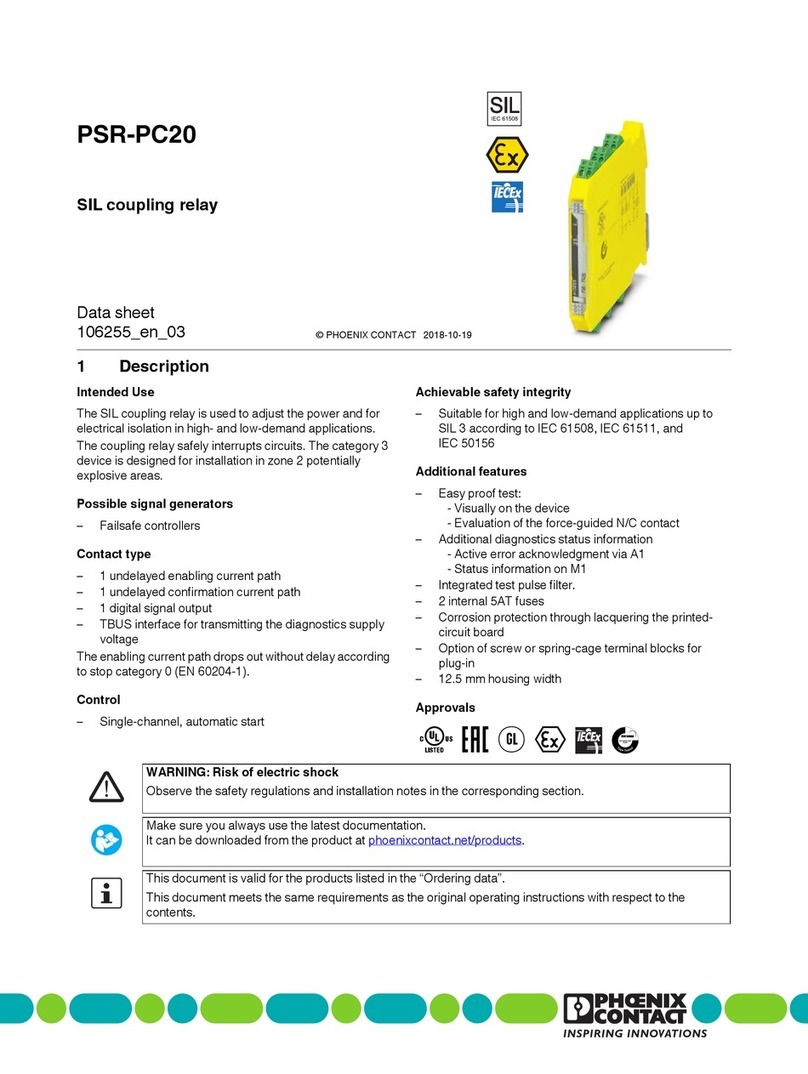
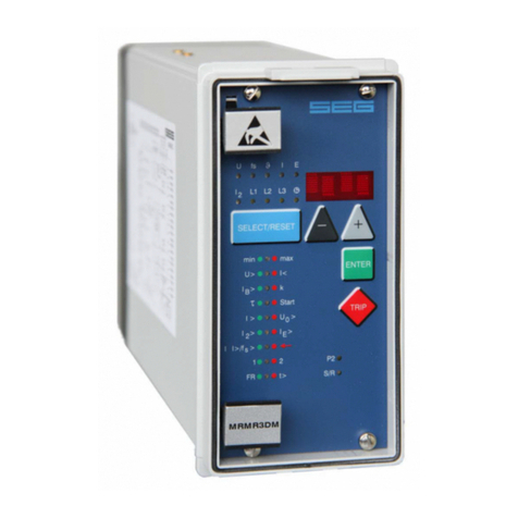
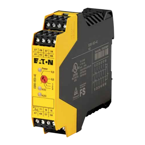
CHINT NXR-12 Installation instructions

NO:2020.04
Standard: IEC/EN 60947-4-1
NXR-12~100
Thermal Overload Relay
User Instruction

Only professional technicians are allowed for installation and
maintenance.
Installation in any damp, condensed-phase environment with
inflammable and explosive gas is forbidden.
When the product is being installed or maintained, the power
must be switched off.
You are prohibited from touching the conductive part when the
product is operating.
1
2
3
4
Safety Warning

01
Use Purpose
1
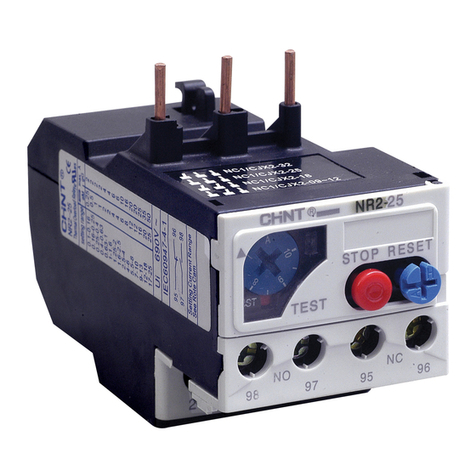
NXR-12~100 thermal overload relay (hereinafter referred to as thermal
relay) is applicable to circuits with frequency of AC 50Hz or 60Hz, rated
operating voltage up to 690V and current from 0.1A to 100A. It is used for
overload protection and phase-failure protection of 3-phase AC motor.
Environment conditions
Ambient temp. (℃)
Hot and humid
atmospheric conditions
Normal operating temperature: -5℃~+40℃
(extreme operating temperature: -35℃~
+70℃), average temperature should not
exceed +35℃ within 24h
Relative humidity should not exceed 50% at
+40℃; up to 90% at +20℃
Pollution class/installation category
Altitude No influence below 2000m
Class 3/Ⅲ
Main Technical Parameters
2
Table 1 Environmental conditions and
technical parameter of main circuit
Table 2 Technical parameters
Model
Phase-failure protection
Manual and automatic reset
Temperature compensation
Tripping indication
Test button
Stop button
Setting current range (A)
NXR-12 NXR-25 NXR-38 NXR-100
Yes
Yes
Yes
Yes
Yes
Yes
0.1-12
Yes
Yes
Yes
Yes
Yes
Yes
0.1-25
Yes
Yes
Yes
Yes
Yes
Yes
23-38
Yes
Yes
Yes
Yes
Yes
Yes
23-100

02
Model NXR-12 NXR-25 NXR-38 NXR-100
Matching contactor NXC-06M,
09M,12M
NXC-06,
09,12,16
NXC-18,22
NXC-25,
32,38
NXC-25,
32,38
NXC-40,
50,65
NXC-75,
85,100
Matching mounting base
Rated insulation voltage Ui
Rated operating voltage Ue
Rated impulse withstand voltage Uimp
MB-1 MB-2 MB-3 MB-4
690V
660/690V
6kV
5A
380/400 V 1.5A
220V 0.2A
1NO 1NC
6A
Auxiliary circuit
Ith
AC-15
DC-13
Auxiliary contact type
Specification of
matching fuse A
Table 3 Combination with fuse
Model
NXR-12
NXR-25
Setting current
range A
Specification of matching fuse
gG (Recommend RT16) A
Sectional area of
connecting wire mm²
0.1~0.16
0.16~0.25
0.25~0.4
0.4~0.63
0.63~1
1~1.6
1.25~2
1.6~2.5
2.5~4
4~6
2
2
2
2
4
4
6
6
10
16
1
Table 2 (continued)

03
Model
NXR-12
NXR-25
Setting current
range A
Specification of matching fuse
gG (Recommend RT16) A
Sectional area of
connecting wire mm²
5.5~8
7~10
9~12
9~13
12~18
17~25
23~32
30~38
23~32
30~40
37~50
48~65
55~70
63~80
80~93
80~100
20
20
25
25
35
50
63
80
63
100
100
100
125
125
160
160
1
1.5
2.5
2.5
2.5
4
6
10
6
10
10
16
25
25
35
35
NXR-12
NXR-25
NXR-38
NXR-100
Table 3 (continued)

04
Figure 1 Operation time – current characteristic curve
0.8 1 1.2 1.5 2 3 4 5 6 7 8 9 10
120
100
80
60
40
20
10
8
6
4
2
1
40
20
10
8
6
4
2
1
min s
heat state
3 phase
2 phase
cold state
2 phase
3 phase
Amplification factor of setting current

05
Installation
3
2)Installation
Figure 2 Thermal relay outline
Figure 3 Combination of thermal relay and mounting base
B
A
A
9
11
13
STOP
TEST
NXR-25
RESET
NO
NC
98 97 96 95
2/T1 4/T2 6/T3
2/T1 4/ T2 6/T3
C
E
H
D
G
F
35

06
Am ax Bmax Cmax E H
FGD
Table 4 Overall dimensions
Model
NXR-12
NXR-25
NXR-38
NXR-100
45
45
55
72
73
67
82
87
68
94
94
117
45
45
55
72
96
93.6
102.9
126.5
75.3
102
102
126
34
35
41
61.5
85.1
55
75.1
109
Figure 4 Assembly of thermal relay and contactor
Unit:mm

07
2) Operation and commissioning
Figure 5 Operation diagram
NO
NC
98 97 96 95
2/ T1 4 /T2 6 /T3
2/T1 4/T 2 6/T3
1/ L1 3 /L2 5/ L3
A
A
A
Stop
Reset
Test
Operation indication
adjustable current range
Automatic reset Manual reset
M3.5
1.2 N.m
M4
1.7 N.m
M10
10 N.m
2
S (mm )
NXR-100
NXR-38
NXR-25
NXR-12
4~35
4~10
1~6
1~4
4~35
A>4mm,
L<12mm
A>4mm,
L<10mm
A>3.5mm,
L<9mm
4~10 4~10 4~10
1~6 1~6 1~6 1~6 1~6
1~4 1~4 1~4 1~4 1~4
M3.5
0.8 N.m
2
mm 2
mm
2
mm 2
mm 2
mm
2
mm
NXR-12~
100
1~2.5
A>3.5mm,
L<8mm
Main
circuit
Auxiliary
circuit
1~2.5 1~2.5 1~2.5 1~2.5 1~2.5
Table 5 Wiring parameters

08
Maintenance
4
Conduct product test and maintenance every half a year to ensure the
smooth operation of the product and the good contact of NO and NC
contacts. Tighten the terminal screws with specified torque and align the
protection capability of the thermal overload relay with load according to
commissioning requirements.
Please be careful when handling and installing the thermal relay. It is
prohibited to move the product by crane with strong impact so that the
product will not be damaged and its protection characteristics will not
change.
Table 6 Analysis and Troubleshooting of Faults
Symptoms Cause analysis Troubleshooting method
and precautions
Misoperation
of thermal
relay without
the motor
being
overloaded.
Thermal relay
does not
operate.
Size is too small.
The set current value is smaller
than the actual operating
current of the motor.
Stong shock or vibration
Frequent start of motor
The sectional area of
connecting wire is too small,
or there is loose connection.
The size is too big
The set current value is bigger
than the actual operating
current of the motor.
The sectional area of
connecting wire is too big.
Thermal
relay does
not work.
The product is not reset.
Auxiliary contacts are not
powered-on.
Main circuit or auxiliary
circuit is burnt
Change to product with bigger size.
Fine tune the cam clockwise so that
the set current matches the actual
motor current.
Check installation status and
conduct troubleshooting. Do not
place the product in environment
with strong shock or vibration.
The start frequency of motor should
not exceed 30 times per hour.
Use standard wire and torque.
Change to product with smaller size.
Fine tune the cam counter-clockwise
so that the set current matches the
actual motor current.
Use standard wire and torque.
Press the reset button to reset the relay.
Replace thermal relay.
Replace thermal relay.

QC PASS
Test date: Please see the packing
ZHEJIANG CHINT ELECTRICS CO.,LTD.
NXR-12~100
Thermal Overload Relay
IEC/EN 60947-4-1
Check 21
09
Environmental Protection
5
In order to protect the environment, the product or product parts
should be disposed of according to the industrial waste treatment process,
or be sent to the recycling station for assortment, dismantling and recycling
according to local regulations.

NXR-12~100
Thermal Overload Relay
User Instruction
Zhejiang Chint Electrics Co., Ltd.
Add: No.1, CHINT Road, CHINT Industrial Zone,North Baixiang,
Yueqing, Zhejiang 325603,P.R.China
E-mail: global-sales@chint.com
Website: http://en.chint.com
This manual suits for next models
3
Table of contents
Other CHINT Relay manuals
