Chippmann Omega-PhiCS-8 Series User manual

CS-8 Series
Owners' Manual
Omega-Phi


CS-8 Series Omega-Phi Rev1.04, Oct. 2015
-1-
User manual b Carsten Schippmann
Graphic design CS-8 Series: Carsten Schippmann
Concept and development: Carsten Schippmann
English translation b Carsten Schippmann
Contact:
Schippmann electronic musical instruments
Dipl.-Ing. Carsten Schippmann
Wartburgstr. 8
D-10823 Berlin
Web: www.schippmann-music.com
Email: info@schippmann-music.com
The manufacturer
Schippmann electronic musical instruments
is constantl
striving for improvements and developments of their products. Therefore, we
reserve the right to change technical specifications which improve our
products at an time without notice. This includes the look of the unit which
might differ from pictures in this manual.
No part of this publication is to be reproduced, transmitted, transcribed or
translated in an form or b an means whatsoever without written
permission b
Schippmann electronic musical instruments
.
2015, Schippmann electronic musical instruments, errors excepted, subject
to change without prior notice.
CS-8 Series Omega-Phi Rev1.04, Oct. 2015
-2-
PREFACE
First of all, congratulations on the purchase of this 3U euro rack s nthesizer
module. This manual contains a condensed description of the functionalit
and addresses users with a certain level of elementar technical knowledge.
The current Thru-Zero
2
࣓
െ
ࢾ࣐
ࢾ࢚
high performan e VCO Omega-Phi of the
CS-8 series is a so-called
thru zero
oscillator (to the power of 2 ☺). Oscillators of
this t pe are able to reverse their curve over time from an point, if the linear
FM control voltage goes thru zero into negative voltages. The oscillators'
frequenc will rise again b further increasing negative voltages but it has
reversed its curve from an where at the zero point of frequenc .
A t pical oscillator is forced to continue its curve to the ver end
(maximum/minimum) before it can change its direction. It will also stop at zero
or negative voltages, which cannot be processed, that it will inevitabl
continue its originall direction to the ver end.
With that "little" technical difference for Thru zero oscillators are arising
extremely signifi ant properties! For t pical oscillators, namel , harmonic
relationships will var with changing modulation depths (Index). I.e., although
the ratio of the carrier frequenc (modulated oscillator) and the modulation
frequenc (modulating oscillator) could be in whole numbers, even harmonic,
the modulation result will be totall disharmonic starting with that point from
where the linear FM voltage goes under zero. Onl for specific singular indices
the result becomes harmonic, for all other indices it's chaotic. A t pical
harmonic percussion sound, well-known from digital FM-S nthesizers, where
the index is modulated from ver high to low, is absolutel impossible for
t pical oscillators. This ONLY works with a Thru zero oscillator!
The ultimate feature of the Omega-Phi is the capabilit of an additional true
phase-modulation section. It is connected downstream to the oscillator core
and it is ver similar to the sound aesthetic of the frequenc modulation, when
using two sine-wave oscillators even identical! Because of the downstream
architecture the possibilit of simultaneousl processing sound s nthesis
arises to create PM sounds (Phi section) and having at the same time clean
standard waves at the core outputs (Omega section) for other s nthesis. But of

CS-8 Series Omega-Phi Rev1.04, Oct. 2015
-3-
course the oscillators' core can be FM'ed and the result can be processed once
again with the Phi section. This creates potential!
Moreover, there exists a number of syn hronization possibilities, ver
interesting intermediate states (between "Thru zero" and "normal"), for each of
the both sections (Omega & Phi) a b one octave decimated sub frequenc
wave and apart from PWM a funn saw-tooth wave-shaping with octave-up
effect as well as at last a round suitable sine-wave.
Furthermore, the frequenc range can be selected ver quickl and reliable b
a 4-pole rotar switch and a toggle switch over seven octaves and from there
another ±1 octave, as well as ±100 cents. The finall frequenc range reaches
from a couple of hundred seconds to umpteen kilohertz.
The oscillator has, thanks of absolute high-tech-components, a ver high
octave linearit , finest temperature stabilit and because of its extremel low
phase-noise (jitter) an extraordinar pure sound and powerful potential.
Design and implementation meet highest technical standards concerning
usabilit , sound qualit , and electromagnetic immunit . The entire design and
production work was done in German . Have fun!
Made in German
CS-8 Series Omega-Phi Rev1.04, Oct. 2015
-4-
1. WARRANTY .........................................................................................................................5
1.1 Limited Warranty ....................................................................................................5
1.2 Terms of Warranty ..................................................................................................5
1.3 Warranty transferability ......................................................................................5
1.4 Claim for damages ..................................................................................................5
2. CE AND FCC COMPLIANCE STATEMENTS ...............................................................6
3. DISPOSAL ............................................................................................................................6
4. SAFETY INSTRUCTIONS .................................................................................................6
5. MAINTAINANCE/ CLEANING ........................................................................................7
6. GETTING STARTET............................................................................................................8
6.1 Unpa king ..................................................................................................................8
6.2 Installation .................................................................................................................8
7. CONTROLS ...........................................................................................................................9
7.1 Front panel .................................................................................................................9
7.2 Ba kside ................................................................................................................... 12
7.3 Initial operation .................................................................................................... 14
8.1. Layout and fun tions......................................................................................... 14
8.2. The e-fun tion-generator ................................................................................ 16
8.3. The VCO ore and its wave-shapes .............................................................. 17
8.4. The linear frequen y modulation FM ......................................................... 19
8.4.1. The FM VCA ........................................................................................................ 22
8.5. The syn hronization se tion .......................................................................... 23
8.6. The phase modulation PM .............................................................................. 25
8.6.1. The PM VCA ........................................................................................................ 27
9. THEORETICAL PRINCIPLES ........................................................................................ 28
9.1. Frequen y modulation FM .............................................................................. 28
9.2. Phase modulation PM ....................................................................................... 29
10.TECHNICAL SPECIFICATIONS AND RATINGS ................................................... 31
10.1 Spe ifi ations (generally) .............................................................................. 31
10.2 Signals and ratings ........................................................................................... 31

CS-8 Series Omega-Phi Rev1.04, Oct. 2015
-5-
1. WARRANTY
1.1 Limited Warranty
Schippmann electronic musical instruments
warrants the mechanical and
electronic components of this product for a period of two (2) ears from the
original date of purchase, according to the warrant regulations described
below. If the product exhibits an faults within the specified warrant period
that are not excluded from this warrant ,
Schippmann electronic musical
instruments
shall, at its discretion, either replace or repair the product. This
warrant exists in addition to the general terms of business of the
manufacturer
Schippmann electronic musical instruments
.
1.2 Terms of Warranty
Schippmann electronic musical instruments
reserves the right to execute
warrant services onl if the product comes with a cop of the dealer’s original
invoice. Final discretion of warrant coverage lies solel with
Schippmann
electronic musical instruments
. An
Schippmann electronic musical
instruments
product deemed eligible for repair or replacement under the
terms of this warrant will be repaired or replaced within 30 da s after
receiving the product at
Schippmann electronic musical instruments
.
Damages or defects caused b improper handling or opening of the unit b
unauthorized personnel (user included) are not covered b this warrant .
Products which do not meet the terms of this warrant will be repaired
exclusivel at the bu er´s expense and returned C.O.D. with an invoice for
labour, materials, return shipping, and insurance. Products repaired under
warrant will be returned with shipping prepaid b
Schippmann electronic
musical instruments
. Outside Germany, produ ts will be returned at the
buyer´s expense.
1.3 Warranty transferability
This warrant is extended to the original purchaser and cannot be transferred.
No other person (retail dealer, etc) shall be entitled to give an warrant
promise on behalf of
Schippmann electronic musical instruments
.
1.4 Claim for damages

CS-8 Series Omega-Phi Rev1.04, Oct. 2015
-6-
Schippmann electronic musical instruments
does not accept claims for
damages of an kind, especiall consequential loss or damage, direct or
indirect of an kind however caused. Liabilit is limited to the value of this
product. The general terms of business drawn up b
Schippmann electronic
musical instruments
appl at all times.
2. CE AND FCC COMPLIANCE STATEMENTS
This device has been tested and deemed to compl with the DIN EN 60065
standards.
This device has been tested and deemed to compl with the requirements,
listed in FCC Regulations, part 15. The device complies with EN 55103-1 and
EN 55103-2 standards.
Because of the entirel analogue construction, this device does not generate
radio frequencies and will not interfere with radio frequencies generated b
other electronic devices.
3. DISPOSAL
This device has been manufactured to RoHS-standards, in compliance with the
requirements of the European parliament and council and is thus free of lead,
mercur , and cadmium.
!! Noti e: This produ t is still spe ial waste and is not to be disposed of
through regular household waste !!
For disposal, please onta t your lo al dealer or Schippmann electronic
musical instruments
4. SAFETY INSTRUCTIONS
BEFORE USING THIS PRODUCT FOR THE FIRST TIME, PLEASE READ THE
ENTIRE USER MANUAL THOROUGHLY.

CS-8 Series Omega-Phi Rev1.04, Oct. 2015
-7-
•PLEASE AVOID SHARP BENDING OF ANY CORDS AND CABLES.
•CORDS SHOULD NOT BE INSTALLED WITHIN THE REACH OF CHILDREN
OR PETS.
•DO NOT TREAD THE ENCLOSURE OF THE PRODUCT, DO NOT PLACE
HEAVY OBJECTS ON IT.
•BEFORE REMOVING THE PRODUCT FROM THE RACK, PLEASE
DISCONNECT THE POWER PLUG AND ALL OTHER CABLE
CONNECTIONS.
•PLEASE DISCONNECT THE POWER PLUG FROM THE OUTLET IN CASE OF
A THUNDERSTORM.
•NEVER OPEN THE ENCLOSURE OF THE PRODUCT! NEVER TRY TO
MODIFY THE INTERNAL CIRCUITRY! ONLY QUALIFIED SERVICE
PERSONNEL IS ALLOWED TO OPEN THE ENCLOSURE.
•DO NOT PLACE OPEN FIRE ON TOP OF THE PRODUCT (CANDLES, ASH
TRAYS, HOT THAI CURRIES ETC).
•NEVER EXPOSE THE PRODUCT TO WATER, BEER, OR MOISTURE.
•ADULTS ARE TO MAKE SURE THAT CHILDREN FOLLOW ALL SAFETY
INSTRUCTIONS. SAME THING GOES FOR PETS.
•AVOID MECHANICAL STRESS OR IMPACT. DO NOT DROP THE PRODUCT;
EVEN IF THERE IS A CONTROL LABELLED "DROP"!.
•DO NOT USE THE PRODUCT WITH TOO MANY OTHER ELECTRONIC
DEVICES RUNNING FROM ONE SINGLE OUTLET, ESPECIALLY IN
CONNECTION WITH EXTENSION CORDS. DO NOT ATTEMPT TO SAVE
MONEY ON CHEAP SOLUTIONS. BUY PROPER HIGH-DUTY POWER
DISTRIBUTORS AND CORDS!
•NEVER USE EXTENSION CORDS WITH LESS MAXIMUM LOAD THAN THE
TOTAL POWER CONSUMPTION OF ALL DEVICES CONNECTED TO A
SINGLE POWER OUTLET COMBINED. OVERLOADING EXTENSION CORDS
CAN CAUSE FIRE.
•AVOID MECHANICAL STRESS ON SOCKETS AND KNOBS SWITCHES.
•PROTECT YOUR SPEAKERS AND EARS (!) AGAINST EXCESSIVE AUDIO
LEVELS. THE CS-8 PHS-28 UNIT IS CAPABLE OF GENERATING
EXTREMELY LOW AS WELL AS EXTREMELY HIGH FREQUENCIES. BOTH
MIGHT CAUSE SERIOUS DAMAGE TO AUDIO EQUIPMENT AND EAR-
DRUMS!
5. MAINTAINANCE/ CLEANING

CS-8 Series Omega-Phi Rev1.04, Oct. 2015
-8-
•BEFORE CLEANING THE PRODUCT, PLEASE DISCONNECT THE POWER
PLUG FROM THE OUTLET OR DISCONNECT THE MODULE FROM ITS
POWER CONNECTOR BY PULLING THE FLAT RIBBON CABLE.
•USE A DRY OR SLIGHTLY MOIST CLOTH OR COMPRESSED AIR FOR
CLEANING. NEVER USE ANY CLEANER OR THINNER (E.G. PAINT THINNER
OR ACETON). PRINTS AND PAINTWORK WILL IMEDIATELY BE
DESTROYED!! ALSO AVOID ALCOHOL (ISOPROPYLIC), GAS, SPIRITS
(SCOTCH SINGLE MALTS, FOR A START) OR ABRASIVE HOUSEHOLD
CLEANERS!
6. GETTING STARTET
6.1 Unpa king
The box should contain the following items:
- 1 x CS-8 Series VCO Omega-Phi 3HE rack-mount module
- 1 x Ribbon cable (20 cm length with two 16 pole IDC-connectors)
- 4 x M3 screws
- 4 x pol prop lene washers
- This owners’ manual
If the content of the box turns out to be incomplete, please get in touch with
our dealer or
Schippmann electronic musical instruments
immediatel . In
case of damage caused in transit, please get back to the responsible carrier
and
Schippmann electronic musical instruments
immediatel . We will support
ou in this case.
6.2 Installation
Place the unit on a clean, dr and sturd surface, or use a suitable ke board
stand or 19” rack. For 19” rack mounting, a suitable rack (3U Eurorack with +/-
12V power suppl rails) is required. The Omega-Phi uses discrete all-analogue
electronics. Thus the oscillator frequenc ma be temperature-sensitive. We
recommend placing the module awa from heat sources such as radiators,
lamps or other units that produce heat (e.g. power amps or internal power
supplies).

CS-8 Series Omega-Phi Rev1.04, Oct. 2015
-9-
7. CONTROLS
7.1 Front panel
Fig. 1 shows the front panel with consecutivel numbered controls and jacks.
Fig. 1 Omega-Phi front panel

CS-8 Series Omega-Phi Rev1.04, Oct. 2015
-10-
1. Depth control – attenuates the modulation signal at jack "2" between 0
and 1
2. Modulation input (envelope s mbol) jack – channels the applied signal
via
Depth
control "1" to the control input of the FM-Index-VCA
3. Coupling 2-pos. toggle switch – selects for the FM-modulation signal at
jack "4" the coupling AC (alternating voltage) or DC (direct current)
4. FM jack (input) – channels the applied signal to the signal input of the
FM-Index-VCA
5. FM pol 2-colour-LED – displa s the current working range of the core
VCO; "green" -> positive frequenc range, "red" -> negative frequenc
range
6. Index control – adjusts the modulation depth FM (at jack "4") at the
control input of the FM-Index-VCA
7. S ale 3-pos. toggle switch – determines the base frequenc (without
applied external control voltages) of the VCO
8. S ale 4-pole rotar switch – determines the base frequenc (without
applied external control voltages) of the VCO
9. Depth control – attenuates the modulation signal at jack "10" between 0
and 1
10. Modulation input (envelope s mbol) jack – channels the applied signal
via
Depth
control via
Depth
control "9" to the control input of the PM-
Index-VCA
11. Polarity 2-pos. toggle switch – selects the polarit of the PM-modulation
input signal at jack "12" (non-inverted or inverted)
12. PM jack (input) – channels the applied signal to the signal input of the
PM-Index-VCA
13. Phi limit 2-colour-LED – displa s the maximum/minimum border of the
possible phase-shift; "green" -> positive phase border, "red" -> negative
phase border
14. Index control – adjusts the modulation depth PM (at jack "12") at the
control input of the PM-Index-VCA
15. Tune control – detunes the frequenc , set b scale, b another ± 1 octave
16. PW control – adjusts the dut -c cle of the variable rectangle signal at
jack "35"
17. Shape control – displaces the progress of the saw-tooth curve at jack
"28" related to the triangle signal (jack "30") at its corner-(reverting)points
18. Saw 2-pos. toggle switch – selects rising or falling saw-tooth output and
activates jack "31" (position "dwn/act") at the same time

CS-8 Series Omega-Phi Rev1.04, Oct. 2015
-11-
19. Fine control – detunes the frequenc , set b scale, b another ± 100 cent
20. Depth control – attenuates the signal at the PWM input at jack "33"
between 0 and 1 and varies the dut c cle of the pulse output (jack "35")
21. Depth control – attenuates the signal at the Shape input at jack "29"
between 0 and 1 and varies the saw-tooth displacement
22. Phi control – adjusts the phase (Phi) of all Phi-outputs (jacks "38", "40",
"42", "45") related to the Omega-outputs (jacks "28", "30", "32", "34", "35")
between ±360°
23. Value control – determines the setting-voltage of the triangle, when a
S nc trigger at jack "27" occurs (±5 V)
24. Bias 2-pos. toggle switch – switches on an internal bias voltage at the
linear-FM-input to generate a basic frequenc ("norm") or of ("Zero")
(oscillator doesn't oscillate an more without voltage at the FM-input)
25. Zero 2-pos. toggle switch – turns on the Thru Zero capabilit (phase
reverse) ("On") or off ("Off")
26. Re tifier 2-pos. toggle switch – determines the method of rectif ing at
the FM-linear input, full-wave ("Full") or half-wave for onl positive input
voltages ("Half (pos)") - this is a special function due to the applied thru
zero architecture
27. Set jack (input) – S nchronization input sets the triangles output value to
the voltage value (adjusted with
Value
control "23") with a positive going
trigger (0 V -> +5 V) (hard s nc)
28. Saw (Symbol) jack (output) – saw-tooth (with shaping) of the VCO core
(Omega), 5 - 10 Vpp
29. Shape jack (input) – CV-input, attenuated b control "17", displa s the
saw-tooth curve
30. Triangle (Symbol) jack (output) – Triangle output of the VCO core
(Omega), 10 Vpp
31. Ramp jack (digital-input) – onl active in position "dwn/act" of the switch
"18", 0 V = saw-tooth rising, +5V (or floating input) = saw-tooth falling
32. Sinus (Symbol) jack (output) – Sine-wave output of the VCO core
(Omega), 10 Vpp
33. PWM jack (input) – CV-input, attenuated b control "20", varies the dut -
c cle at jack "35"
34. Sub Re tangle (Symbol) jack (output) – 50%-rectangle output
decremented b one octave, 10 Vpp
35. Pulse (Symbol) jack (output) – rectangle output with variable dut -c cle
of the VCO core (Omega), 10 Vpp

CS-8 Series Omega-Phi Rev1.04, Oct. 2015
-12-
36. 1V/O t. jack (input) – CV-input for calibrated exponential control of the
oscillator frequenc (Omega & Phi) with a sensitivit of one octave per
Volt
37. 0.5V/O t. (non- al.) jack (input) – CV-input for non-calibrated
exponential control of the oscillator frequenc (Omega & Phi) with a
sensitivit of two octaves per Volt
38. Saw (Symbol) jack (output) – saw-tooth (with Shaping) of the Phase
section (Phi), 5 - 10 Vpp
39. Zero Crs jack (output) – Output of the Zero-Cross-Detector of the FM-
linear input, 5 Vpp - this is a special function due to the applied thru zero
architecture
40. Triangle (Symbol) jack (output) – Triangle output of the phase section
(Phi), 10 Vpp
41. Up jack (input) – S nchronization input sets the triangles direction to rise
up with a positive going trigger (0 V -> +5 V) (soft s nc)
42. Sinus (Symbol) jack (output) – Sine-wave output of the phase section
(Phi), 10 Vpp
43. Down jack (input) – S nchronization input sets the triangles direction to
fall down with a positive going trigger (0 V -> +5 V) (soft s nc)
44. Sub Re tangle (Symbol) jack (output) – 50%-rectangle output (Phi
section) decremented b one octave, 10 Vpp
45. Reverse jack (input) – S nchronization input sets the triangles direction
to its current opposite direction (reverse) with a positive going trigger (0 V
-> +5 V) (soft s nc)
7.2 Ba kside
Fig. 2 shows the back of the module with consecutivel numbered elements.
CS-8 Series Omega-Phi Rev1.04, Oct. 2015
-13-
Fig. 2 back side of the module
1. THD off1 12-gauge-Trimmer P9 – THD-calibration of Sinus' (Omega-
Output)
2. THD g1 12-gauge-Trimmer P8 – THD- calibration of Sinus' (Omega-
Output)
3. IC 1 - pinned VCO module
4. THD g2 12-gauge-Trimmer P10 – THD- calibration of Sinus' (Phi-Output)
5. THD off2 12-gauge-Trimmer P9 – THD- calibration of Sinus' (Phi-Output)
6. Range 0 25-gauge-Trimmer P2 – calibration of the lowest basic frequenc
(55 Hz)

CS-8 Series Omega-Phi Rev1.04, Oct. 2015
-14-
7. Range MID 25-gauge-Trimmer P5 – calibration of the standard A (440 Hz)
8. Range high 25-gauge-Trimmer P4 – calibration of the upper frequenc
(7040 Hz, upper row)
9. ZERO 25-gauge-Trimmer P12 – calibration to 0 Hz at Bias = Zero & exp.
frequenc = 50 kHz
10. korr high 25-gauge-Trimmer P1 – calibration of gain error of the e-
generator at 20 kHz
11. PVCA off 12-gauge-Trimmer P6 – Offset-calibration of the phase
modulation-VCA's
12. 1 V/ OCT 25-gauge-Trimmer P3 – calibration of the scale at jack "36" to 1
Volt/octave
13. FVCA off 12-gauge-Trimmer P7 – Offset-calibration of the frequenc
modulation-VCA
14. 16 Pin power supply-box header
7.3 Initial operation
The power connector’s (8) pin-out in top view (refer to fig. 2) is assigned as
follows:
Bottom to top, left to right. Thus pin 1 is located at bottom left, pin 2 above pin
1 etc. Pin 15 is at bottom right, pin 16 at top right.
Pin 1, 2 = -12 V (labeled with a triangle)
Pin 3-8 = GND (regarding ground, 0 V), located outward on all jacks
Pin 9, 10 = +12 V
Pin 11-16 = not connected
To hook up power to the module, connect one of the IDC-connector of the
included flat ribbon cable to the box header (refer to fig. 2). Observe guide ke
for the polarit of the connector in order to avoid pin reversal. The red tag of
the cable is to match the triangle-label.
8. MODULE DESCRIPTION
8.1. Layout and fun tions
CS-8 Series Omega-Phi Rev1.04, Oct. 2015
-15-
Rectifier
SUM
+5 V
Biasoff
Coupling
AC
VCA
FM
Σ
+5 V
-5 V
Index
Depth
S ale
Full Half
Exp-Generator
SUM
upper
lower
LFO
55/880
110/1760
220/3520
440/7040
Tune
Fine
1 V/Oct.0.5 V/Oct.
U
LIN
exp(U
sum
)
U
LIN
Zero cross
Detector
green/red
VCO core
& Wave-
shaping
Off On
Zero
Value
PW
Zero Crs
Up
Down
Reverse
Set
Syn
Depth
PWM
Depth
Shape
Shape
Ramp
Triangle
Sine
Pulse
50% sub Rectangle
Sawtooth
Omega
up
dwn/act
Saw
FM pol
+5 V
-5 V
Fig. 3a Structure of the VCO core
CS-8 Series Omega-Phi Rev1.04, Oct. 2015
-16-
PM Phase-ShifterSUM
Polarity
0°
VCA
Σ
+5 V
-5 V
Index
Depth
green/red
-1
180°
+5 V
-5 V
Phi
Phi limit
VCO core
Omega
Triangle
Sine
50% sub Rectangle
Sawtooth
Phi
Fig. 3b Structure of the phase-shifting section
Fig. 3a and 3b showing the complete structure of the oscillator. Now, step b
step all parts of it will be described in the following chapters.
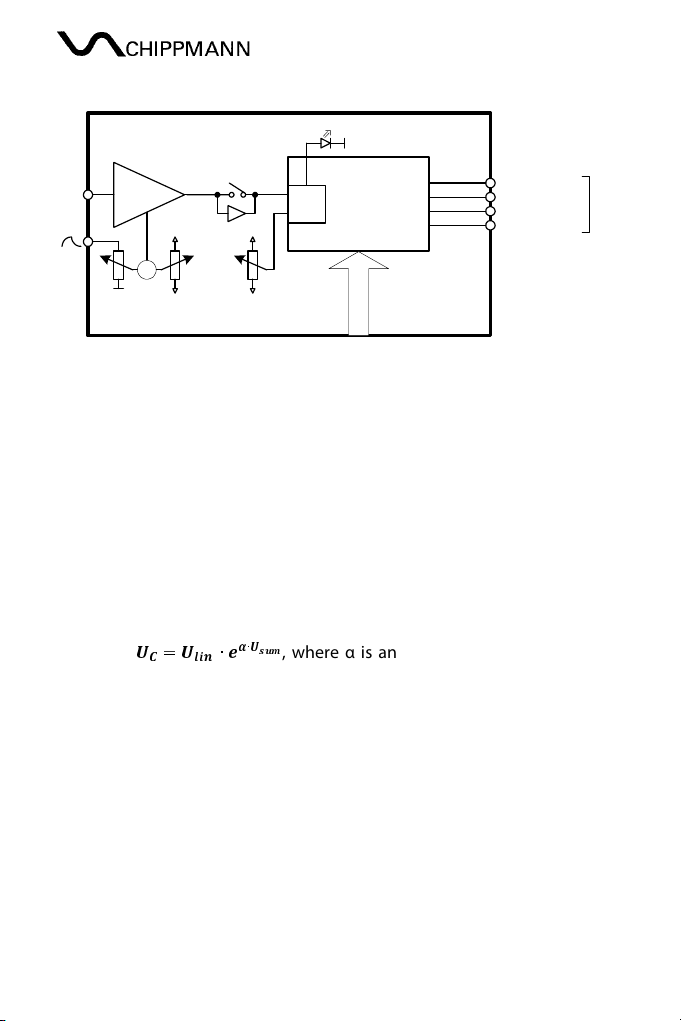
8.2. The e-fun tion-generator
An e-function-generator (Exp-Generator, Fig. 3a) is mostl part of ever music
VCO. The have a linear input and the exponential input. The linear one is
scaled Hertz/Volt and the exponential one in octaves/Volt or decades/Volt.
Generall , for resulting voltage output U
C
one obtain the mathematical
expression:
ࢁ
ൌ
ࢁ
∙
∙
࢙࢛
, where α is an exponential scaling-factor and
U
sum
the total input voltage at the exponential input (following called e-input)
and it is the result of the following parts. First of all there are the Scale-
switches.
S ale-switches: The 3-position toggle switch (
upper, lower, LFO
) determines
the range of the 4-position-rotar switch. In position "lower" the lower row of
frequencies of the rotar switch will be output b the VCO core (no further
control voltages applied) in steps of octaves 55 Hz, 110 Hz, 220 Hz and 440 Hz.
In position "upper" it is the upper row also in octave steps 880 Hz, 1760 Hz,
3520 Hz and 7040 Hz. In position "LFO" the oscillators frequenc at "55 Hz"-
position of the rotar switch and at full CCW (counter clockwise) of the
Tune
-
controller is about 0.08 Hz.
CS-8 Series Omega-Phi Rev1.04, Oct. 2015
-17-
Tune: The normal position of this controller is the middle. In the positions
"upper" and "lower" it decrements/increments (left/right) the oscillators'
frequenc b
1 octave (a bit more). In position "LFO" it has a much wider
range. In position "55 Hz" the frequenc ranges (from left to right) from about
0.08 Hz to 12 Hz, that's a factor of 150 and equals 7.2 octaves. The rotar switch
still octaves the frequencies. So, in position "440 Hz"
Tune
ranges from 0.64 Hz
to about 100Hz. Fine, so far.
Fine: This controller was intended for finest frequenc corrections and definite
beats. Normal position is the middle and it detunes the frequenc once again
b
100 cent (a bit more). 100 cent equals a semitone step at the equall -
temperate scale.
1 V/O t-jack: An external voltage at that jack increments (or decrements) the
current oscillator frequenc with a sensitivit of one octave (x2) per +Volt, resp.
(
2) per -Volt (negative voltages). This input is calibrated.
0.5 V/O t-jack: An external voltage at that jack increments (or decrements) the
current oscillator frequenc with a sensitivit of two octaves (x4) per +Volt,
resp. (
4) per -Volt (negative voltages). This input is not calibrated, i.e. this
scale is tolerant with some percent and different from VCO to VCO.
Each of these influence quantities at the e-input operates b a frequenc
multiplication not b summing!
8.3. The VCO ore and its wave-shapes
The VCO output its frequenc as different waveforms, which are sinus, triangle,
saw-tooth, variable rectangle and a 50% rectangle with half frequenc (one
octave down). Fig. 4 shows these functions and there phase relations e.g. as
voltage versus time.

CS-8 Series Omega-Phi Rev1.04, Oct. 2015
-18-
SUB 50% Rectangle
Pulse
PW mid
PW left
PW right
Saw - shape right
Saw - shape right side
Saw - shape mid
Saw - shape left side
Saw - shape left
Triangle (reference)
Sinus
Fig. 4 The waveforms of the VCO core (Omega-outputs)
The triangle is the reference for all other waveforms.
PW/PWM/Depth: The controller
PW
determines as shown in the graph the
dut -c cle from 0% (full CCW) to 100% (full clockwise, CW) of the pulse wave.
Table of contents


