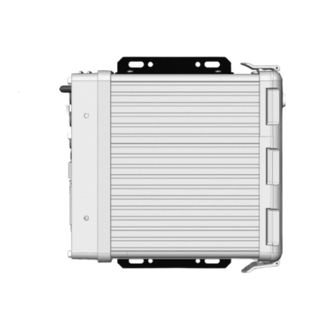
CHK Power Quality MIRO PQ25 User manual

CHK Power Quality Pty Ltd, User Manual –Miro Power Quality Logger and Analyser, 15 August 2016
Website: www.chkpowerquality.com.au; Enquiries: [email protected]; Page 1
Address: Unit 1, 3 Tollis Place, Seven Hills, NSW 2147, Sydney, Australia; ABN: 53 169 840 831; Telephone: +61 2 8283 6945;
Fax: +61 2 8212 8105; Website: www.chkpowerquality.com.au
MIRO
Power Quality Logger and Analyser
MODELS: PQ25/35/45
User Manual

CHK Power Quality Pty Ltd, User Manual –Miro Power Quality Logger and Analyser, 15 August 2016
Website: www.chkpowerquality.com.au; Enquiries: [email protected]; Page 2
Address: Unit 1, 3 Tollis Place, Seven Hills, NSW 2147, Sydney, Australia; ABN: 53 169 840 831; Telephone: +61 2 8283 6945;
Fax: +61 2 8212 8105; Website: www.chkpowerquality.com.au
Contents
1 PRODUCT OVERVIEW..................................................................................................... 8
1.1 Product brief................................................................................................................ 8
1.1.1 Feature summary.................................................................................................................8
1.1.1.1 Scientific grade.....................................................................................................8
1.1.1.2 Compact design....................................................................................................8
1.1.1.3 Power supply options ...........................................................................................8
1.1.1.4 All weather conditions...........................................................................................8
1.1.1.5 Safety....................................................................................................................8
1.1.1.6 Communications...................................................................................................8
1.1.1.7 Software interface.................................................................................................8
1.1.1.8 Transformer monitoring........................................................................................9
1.1.1.9 DC system monitoring ..........................................................................................9
1.1.1.10 Model category...................................................................................................9
1.1.1.11 Expansion port....................................................................................................9
1.1.1.12 Accessories ........................................................................................................9
1.1.2 Connections and interfaces.................................................................................................9
1.2 Kits and accessories.................................................................................................. 11
1.2.1 PQ25/35/45 kits .................................................................................................................11
1.2.2 Instruments........................................................................................................................11
1.2.3 Accessories........................................................................................................................11
1.2.3.1 Current sensors and converters.........................................................................12
1.2.3.2 Voltage leads and attachments..........................................................................12
1.2.3.3 Other...................................................................................................................13
1.3 Power options............................................................................................................ 13
1.4 Internal backup battery.............................................................................................. 13
2 EQUIPMENT MAINTENANCE......................................................................................... 14
2.1 Periodic maintenance and testing.............................................................................. 14
2.2 Equipment faults........................................................................................................ 14
2.3 Calibration................................................................................................................. 14
2.4 Cleaning.................................................................................................................... 14
3 SAFE USE OF THE INSTRUMENT................................................................................. 15
4 INSTALLING YOUR INSTRUMENT................................................................................ 16
4.1 Pre-installation check................................................................................................. 16
4.2 Hazard assessment................................................................................................... 16
4.3 Live low voltage work................................................................................................. 16
4.4 Pole Mounting............................................................................................................ 16
4.4.1 Using a holster and strap...................................................................................................16
4.4.2 Using a back-plate.............................................................................................................17
4.5 Connecting the Miro................................................................................................... 17
4.6 Post-installation checks............................................................................................. 18
4.7 Disconnecting the Miro.............................................................................................. 19
5 CITRUS APPLICATION SOFTWARE ............................................................................. 20

CHK Power Quality Pty Ltd, User Manual –Miro Power Quality Logger and Analyser, 15 August 2016
Website: www.chkpowerquality.com.au; Enquiries: [email protected]; Page 3
Address: Unit 1, 3 Tollis Place, Seven Hills, NSW 2147, Sydney, Australia; ABN: 53 169 840 831; Telephone: +61 2 8283 6945;
Fax: +61 2 8212 8105; Website: www.chkpowerquality.com.au
5.1 Installing the Citrus application software.................................................................... 20
5.2 Connecting to the Miro............................................................................................... 21
5.3 Online monitor........................................................................................................... 26
5.3.1 Aggregation interval...........................................................................................................26
5.3.2 Trigger event......................................................................................................................27
5.3.3 Sampling rate.....................................................................................................................27
5.3.4 Timestamp.........................................................................................................................27
5.3.5 RMS and power.................................................................................................................27
5.3.6 Phasor diagram..................................................................................................................28
5.3.7 RMS plot ............................................................................................................................29
5.3.8 Harmonic magnitude (table) ..............................................................................................30
5.3.9 Harmonic magnitude (bar chart)........................................................................................31
5.3.10 Harmonic phase...............................................................................................................34
5.3.11 Harmonic power (bar chart).............................................................................................34
5.3.12 Interharmonics.................................................................................................................35
5.3.13 Flicker ..............................................................................................................................35
5.3.14 Events..............................................................................................................................36
5.3.14.1 No events..........................................................................................................36
5.3.14.2 Listed events ....................................................................................................37
5.3.14.3 Event information..............................................................................................37
5.3.14.4 Trace selection .................................................................................................38
5.3.14.5 Zooming............................................................................................................39
5.3.14.6 Examples of RMS and Mains Signalling events...............................................40
5.3.14.7 Examples of Coupled Mains Signalling + RMS events ....................................42
5.3.14.8 Combining charts..............................................................................................44
5.3.15 Waveforms.......................................................................................................................45
5.4 Configuration............................................................................................................. 47
5.4.1 General..............................................................................................................................48
5.4.1.1 Configuration description....................................................................................48
5.4.1.2 Reset to default ..................................................................................................48
5.4.1.3 Enable and disable log points.............................................................................48
5.4.1.4 Log start and stop date-times.............................................................................49
5.4.1.5 Log memory usage.............................................................................................49
5.4.1.6 Load from and save to file..................................................................................49
5.4.1.7 Save configuration to device ..............................................................................49
5.4.2 Inputs.................................................................................................................................49
5.4.2.1 Nominal frequency..............................................................................................49
5.4.2.2 Nominal voltage..................................................................................................50
5.4.2.3 Circuit connection...............................................................................................50
5.4.2.4 Channels.............................................................................................................50
5.4.2.5 High sensitivity coil .............................................................................................50
5.4.3 Log intervals.......................................................................................................................50
5.4.4 RMS and Power.................................................................................................................52
5.4.5 Harmonics & Flicker...........................................................................................................53
5.4.6 Mains Signalling.................................................................................................................53
5.4.7 IEC events .........................................................................................................................54
5.4.8 Capture triggers.................................................................................................................54
5.4.9 Capture types.....................................................................................................................55
5.4.10 LCD pages.......................................................................................................................55
5.4.10.1 Information........................................................................................................56

CHK Power Quality Pty Ltd, User Manual –Miro Power Quality Logger and Analyser, 15 August 2016
Website: www.chkpowerquality.com.au; Enquiries: [email protected]; Page 4
Address: Unit 1, 3 Tollis Place, Seven Hills, NSW 2147, Sydney, Australia; ABN: 53 169 840 831; Telephone: +61 2 8283 6945;
Fax: +61 2 8212 8105; Website: www.chkpowerquality.com.au
5.4.10.2 RMS..................................................................................................................56
5.4.10.3 Current sensor types........................................................................................56
5.4.10.4 Temperature.....................................................................................................56
5.4.10.5 Power................................................................................................................56
5.4.10.6 Power factor .....................................................................................................56
5.4.10.7 Flicker...............................................................................................................56
5.4.10.8 Phasor diagram ................................................................................................56
5.4.10.9 Voltage waveform.............................................................................................57
5.4.10.10 Current waveform...........................................................................................57
5.4.10.11 User page.......................................................................................................57
5.4.10.12 Comms status.................................................................................................57
5.4.10.13 GPS status .....................................................................................................57
5.4.10.14 Common page information.............................................................................58
5.4.11 Comms.............................................................................................................................58
5.4.11.1 Australian mobile phone networks band summary ..........................................59
5.4.11.2 Cellular module.................................................................................................59
5.4.11.3 Cellular option outside Australia.......................................................................59
5.5 Downloading and clearing memory............................................................................ 60
5.5.1 Downloading data..............................................................................................................60
5.5.2 Downloading with clear memory........................................................................................63
5.6 Clearing memory....................................................................................................... 65
5.7 Set time..................................................................................................................... 66
5.8 Firmware update........................................................................................................ 66
5.9 Miro data viewer........................................................................................................ 66
5.9.1 File .....................................................................................................................................68
5.9.1.1 Open...................................................................................................................68
5.9.1.2 Add file................................................................................................................69
5.9.1.3 Remove file.........................................................................................................70
5.9.1.4 Exit......................................................................................................................71
5.9.2 View ...................................................................................................................................72
5.9.2.1 Save view to log file............................................................................................72
5.9.2.2 Load saved view.................................................................................................73
5.9.2.3 Set zoom.............................................................................................................74
5.9.2.4 Cursors...............................................................................................................77
5.9.2.5 Add title...............................................................................................................84
5.9.2.6 Add notes as footer ............................................................................................86
5.9.2.7 Add text annotation.............................................................................................87
5.9.2.8 Add arrow annotation .........................................................................................89
5.9.2.9 Toggle split/combine...........................................................................................92
5.9.2.10 Toggle date /time mode....................................................................................96
5.9.2.11 Close tabs.........................................................................................................98
5.9.3 Export...............................................................................................................................100
5.9.3.1 Print ..................................................................................................................100
5.9.3.2 Generate PDF...................................................................................................101
5.9.3.3 Generate PNG..................................................................................................102
5.9.3.4 Generate SVG..................................................................................................102
5.9.3.5 Copy to clipboard..............................................................................................102
5.9.3.6 Generate CSV ..................................................................................................103
5.9.3.7 Generate table..................................................................................................104

CHK Power Quality Pty Ltd, User Manual –Miro Power Quality Logger and Analyser, 15 August 2016
Website: www.chkpowerquality.com.au; Enquiries: [email protected]; Page 5
Address: Unit 1, 3 Tollis Place, Seven Hills, NSW 2147, Sydney, Australia; ABN: 53 169 840 831; Telephone: +61 2 8283 6945;
Fax: +61 2 8212 8105; Website: www.chkpowerquality.com.au
5.9.4 Measurements.................................................................................................................105
5.9.4.1 RMS and frequency..........................................................................................105
5.9.4.2 Power and unbalance.......................................................................................112
5.9.4.3 Harmonics.........................................................................................................119
5.9.4.4 Flicker...............................................................................................................121
5.9.4.5 Temperature.....................................................................................................123
5.9.5 Events..............................................................................................................................124
5.9.5.1 Event filters.......................................................................................................125
5.9.5.2 Event selection via up /down buttons...............................................................127
5.9.5.3 Combining charts..............................................................................................128
5.9.5.4 Trace selection .................................................................................................129
5.9.5.5 Reload button ...................................................................................................129
5.9.5.6 Voltage as % of nominal...................................................................................129
5.9.5.7 Add title.............................................................................................................130
5.9.5.8 Add cursors.......................................................................................................131
5.9.5.9 Clipboard ..........................................................................................................132
5.9.5.10 Print ................................................................................................................132
5.9.5.11 Export PDF.....................................................................................................133
5.9.5.12 Export table ....................................................................................................134
5.9.6 Analysis............................................................................................................................136
5.9.6.1 Harmonic average ............................................................................................136
5.9.6.2 Harmonic compliance.......................................................................................137
5.9.6.3 Voltage compliance ..........................................................................................142
5.9.6.4 Energy ..............................................................................................................148
5.9.6.5 Daily min / max.................................................................................................150
5.9.6.6 ITI (CBEMA) curve ...........................................................................................151
5.9.7 View Configuration...........................................................................................................153
5.9.7.1 Multiple configurations......................................................................................153
5.9.8 Device information...........................................................................................................154
5.9.9 Notes................................................................................................................................154
5.9.10 Tools ..............................................................................................................................156
5.9.10.1 Merge open files.............................................................................................156
5.9.10.2 Split file...........................................................................................................157
5.9.11 Options...........................................................................................................................159
5.9.11.1 Time zones.....................................................................................................159
5.9.11.2 Colour settings................................................................................................160
5.9.12 Help................................................................................................................................161
5.9.13 Graph setup...................................................................................................................162
5.9.13.1 Log intervals ...................................................................................................162
5.9.13.2 Channel filter ..................................................................................................162
5.9.13.3 Display values ................................................................................................162
5.9.13.4 Date filter ........................................................................................................162
5.9.13.5 Graphical output .............................................................................................168
5.9.13.6 Timeframes.....................................................................................................169
5.9.13.7 Event summary...............................................................................................170
5.9.14 Version number..............................................................................................................172
6 TROUBLESHOOTING................................................................................................... 173
6.1 The Miro does not start up after applying power...................................................... 173
6.2 The Miro does not display voltage and/or current values......................................... 173

CHK Power Quality Pty Ltd, User Manual –Miro Power Quality Logger and Analyser, 15 August 2016
Website: www.chkpowerquality.com.au; Enquiries: [email protected]; Page 6
Address: Unit 1, 3 Tollis Place, Seven Hills, NSW 2147, Sydney, Australia; ABN: 53 169 840 831; Telephone: +61 2 8283 6945;
Fax: +61 2 8212 8105; Website: www.chkpowerquality.com.au
6.3 The Miro displays incorrect voltage/current values .................................................. 173
6.4 The Miro LCD shuts down immediately after removing power ................................. 173
6.5 The Miro does not communicate with the PC using Citrus software......................... 174
6.6 The Miro date and time are not correct.................................................................... 174
7 SUPPORT SERVICES................................................................................................... 175
7.1 Operational information ........................................................................................... 175
7.2 Firmware and software upgrades............................................................................. 175
7.3 Technical sales and assistance............................................................................... 175
7.4 Calibration............................................................................................................... 175
7.4.1 Acceptance testing ..........................................................................................................175
7.4.1.1 Voltage calibrators............................................................................................175
7.4.1.2 Suitable voltage sources ..................................................................................178
7.5 Equipment maintenance.......................................................................................... 178
7.6 Cleaning and decontamination ................................................................................ 178
8 INSTRUMENT SPECIFICATIONS................................................................................. 180
8.1 Hardware specifications........................................................................................... 180
8.2 Software features .................................................................................................... 183
9 ACCESSORIES............................................................................................................. 184
9.1 Voltage leads........................................................................................................... 184
9.1.1 Single phase leads ..........................................................................................................184
9.1.2 Three phase leads...........................................................................................................184
9.1.3 PQ35 three phase leads..................................................................................................185
9.1.3.1 VL3 ...................................................................................................................185
9.1.3.2 VL4 ...................................................................................................................185
9.1.3.3 VL4 voltage lead attachments..........................................................................186
9.1.3.4 VL6 ...................................................................................................................187
9.1.4 PQ45 three phase leads..................................................................................................188
9.1.4.1 VL5-B................................................................................................................188
9.1.4.2 VL5-C................................................................................................................189
9.1.4.3 VL8-B................................................................................................................190
9.1.4.4 VL8-C................................................................................................................191
9.2 Current probes......................................................................................................... 192
9.2.1 PQ35 current probes .......................................................................................................192
9.2.1.1 Flexible high sensitivity coil F-500/3000 (Red).................................................192
9.2.1.2 Flexible coil 3000 (Blue) ...................................................................................192
9.2.1.3 Flexible coil 3000 (Green) ................................................................................193
9.2.1.4 Clamp on CT probes 52mm - 100A..................................................................193
9.2.1.5 Clamp on CT probes 52mm - 500A..................................................................194
9.2.1.6 Clamp on CT probes 52mm - 1000A................................................................194
9.2.1.7 Clamp on CT probes 15mm - 100A..................................................................195
9.2.1.8 Clamp on AC + DC probes 50mm....................................................................195
9.2.2 PQ45 current probes .......................................................................................................196
9.2.2.1 Flexible high sensitivity coil F-500/3000 (Red).................................................196
9.2.2.2 Flexible coil 3000 (Blue) ...................................................................................196
9.2.2.3 Flexible coil 3000 (Green) ................................................................................197
9.2.2.4 Clamp on CT probes 52mm - 100A..................................................................197

CHK Power Quality Pty Ltd, User Manual –Miro Power Quality Logger and Analyser, 15 August 2016
Website: www.chkpowerquality.com.au; Enquiries: [email protected]; Page 7
Address: Unit 1, 3 Tollis Place, Seven Hills, NSW 2147, Sydney, Australia; ABN: 53 169 840 831; Telephone: +61 2 8283 6945;
Fax: +61 2 8212 8105; Website: www.chkpowerquality.com.au
9.2.2.5 Clamp on CT probes 52mm - 500A..................................................................198
9.2.2.6 Clamp on CT probes 52mm - 1000A................................................................198
9.2.2.7 Clamp on CT probes 15mm - 10A....................................................................199
9.2.2.8 Clamp on CT probes 15mm - 100A..................................................................199
9.2.2.9 Clamp on AC + DC probes 50mm....................................................................200
9.3 Temperature probes................................................................................................ 201
9.4 Antennas................................................................................................................. 202
9.4.1 GPS antennas..................................................................................................................202
9.4.2 Cellular antennas.............................................................................................................202
9.4.3 Combined GPS + Cellular antennas................................................................................202
9.5 Other....................................................................................................................... 203
9.5.1 DC power adaptor............................................................................................................203
9.5.2 Communications cable ....................................................................................................203
9.5.3 Carry bag.........................................................................................................................203
10 INSTRUMENT VOLTAGE CONNECTOR PINOUTS................................................... 204
10.1 PQ25 and PQ35.................................................................................................... 204
10.2 PQ45..................................................................................................................... 205
11 CIRCUIT CONNECTIONS ........................................................................................... 206
11.1 Star/Wye................................................................................................................ 206
11.1.1 Three phase 4 wire Wye source with Wye load (VL4 cable).........................................206
11.1.2 Three phase 4 wire Wye source with Wye load (VL5 cable).........................................207
11.1.3 Three phase 4 wire Wye source with Wye load (VL6 cable).........................................208
11.2 Delta...................................................................................................................... 209
11.2.1 Three phase 3 wire Delta source with Delta load (VL3 cable) ......................................209
11.2.2 Three phase 3 wire Delta source with Delta load (VL6 cable) ......................................210
11.2.3 Three phase 3 wire Delta source with Delta load (VL8 cable) ......................................211
11.2.4 Three phase 2-Watt 3 wire Delta source with Delta load (VL3 cable)...........................212
11.2.5 Three phase 2-Watt 3 wire Delta source with Delta load (VL6 cable)...........................213
11.2.6 Three phase 2-Watt 3 wire Delta source with Delta load (VL8 cable)...........................214
11.3 Split phase............................................................................................................. 215
11.3.1 Split phase 3 wire with 2 single phase loads (VL4 cable) .............................................215
11.3.2 Split phase with 2 single phase loads (VL5 cable) ........................................................216
11.3.3 Split phase 3 wire with 2 single phase loads (VL6 cable) .............................................217
11.4 Single phase.......................................................................................................... 218
11.4.1 Single phase (VL4 cable)...............................................................................................218
11.4.2 Single phase (VL5 cable)...............................................................................................219
11.4.3 Single phase (VL6 cable)...............................................................................................220
11.5 Generic.................................................................................................................. 221
11.5.1 3 independent circuits (VL6 cable) ................................................................................221
11.5.2 4 independent circuits (VL8 cable) ................................................................................222

CHK Power Quality Pty Ltd, User Manual –Miro Power Quality Logger and Analyser, 15 August 2016
Website: www.chkpowerquality.com.au; Enquiries: [email protected]; Page 8
Address: Unit 1, 3 Tollis Place, Seven Hills, NSW 2147, Sydney, Australia; ABN: 53 169 840 831; Telephone: +61 2 8283 6945;
Fax: +61 2 8212 8105; Website: www.chkpowerquality.com.au
1Product overview
1.1 Product brief
The MIRO Class A range of portable power quality (PQ) recorders are precision instruments
that offer comprehensive and reliable compliance monitoring of low voltage circuits. Built for
high performance, toughness and focus on ease of use, the MIRO range are the workhorse
instruments of choice for a variety of power monitoring applications including power quality
analysis, supply compliance checks and voltage investigations, power flow studies, energy
audits, photovoltaic –solar, railway systems, and transformer monitoring
1.1.1 Feature summary
1.1.1.1 Scientific grade
Designed to Class A, IEC61000-4-30.
1.1.1.2 Compact design
The MIRO PQ is designed to meet applications for the modern marketplace and where
space and accessibility are restrictive.
1.1.1.3 Power supply options
Powered from Phase A and external DC.
1.1.1.4 All weather conditions
Rugged, shock resistant, portable and weatherproof (IP66).
1.1.1.5 Safety
Voltage transients: Minimum CAT IV 600V safety category
> 10kV isolation to ground
> 10kV isolation between voltage channels
Removable voltage leads
Voltage leads independently certified to CAT IV 600V
Reinforced insulation / double insulated
1.1.1.6 Communications
All local and remote communications options are integrated within the standard enclosure -
no additional peripherals required other than an external antenna. Remote communications
options include: 2G/3G and other cellular platforms.
1.1.1.7 Software interface
The CITRUS platform is powerful, easy to use and intuitive application software that
supports all CHK PQ products. It provides tools for: device management; data analysis; and
reporting.

CHK Power Quality Pty Ltd, User Manual –Miro Power Quality Logger and Analyser, 15 August 2016
Website: www.chkpowerquality.com.au; Enquiries: [email protected]; Page 9
Address: Unit 1, 3 Tollis Place, Seven Hills, NSW 2147, Sydney, Australia; ABN: 53 169 840 831; Telephone: +61 2 8283 6945;
Fax: +61 2 8212 8105; Website: www.chkpowerquality.com.au
1.1.1.8 Transformer monitoring
The incorporation of two temperature channels ideally lends the instrument to transformer
monitoring applications. Additional measurements specific to transformer monitoring are
available upon request.
1.1.1.9 DC system monitoring
Each current and voltage channel (using the appropriate current probe) can also measure
DC components and hence extends the instrument applications to photovoltaic and railway
systems.
1.1.1.10 Model category
Two model categories: Single phase and three phase versions.
Single phase:
oPQ25 (2 voltage and 2 current channels).
3 phase:
oPQ35 (3 voltage and 4 current channels).
oPQ45 (4 voltage and 4 current channels).
1.1.1.11 Expansion port
This port allows for system expansion to include additional sensors, input/output controls
and custom interfaces.
1.1.1.12 Accessories
ALL Powermonic PM35 and PM45 accessories can be used with the PQ35 and PQ45
models respectively.
1.1.2 Connections and interfaces
Photos in figures 1.1.2.1, 1.1.2.2, 1.1.2.3 and 1.1.2.4 show ports and hardware interfaces.
A: Voltage lead connector. It can accommodate up to four (4) voltages.
B: Current probe connectors. The channels are designated as A, B, C, and N to
accommodate three phase systems. The current channels can accept Rogowski coils,
clamp-on CTs and DC probes.
C: Graphical liquid crystal display (LCD). The LCD can be configured to display pages with
each page displayed for approximately three seconds. The pages commence to display
upon the application of power. Each page includes
D: Data (USB) connector (top); External DC power (bottom).
E: Temperature connectors. Two external temperatures are available for correlating PQ data
and temperature measurements.
F: Expansion port. Used for USB communications and for an external power adaptor.
G: GPS antenna (left); Cellular antenna (right).

CHK Power Quality Pty Ltd, User Manual –Miro Power Quality Logger and Analyser, 15 August 2016
Website: www.chkpowerquality.com.au; Enquiries: [email protected]; Page 10
Address: Unit 1, 3 Tollis Place, Seven Hills, NSW 2147, Sydney, Australia; ABN: 53 169 840 831; Telephone: +61 2 8283 6945;
Fax: +61 2 8212 8105; Website: www.chkpowerquality.com.au
Figure 1.1.2.1 - Miro PQ35
Figure 1.1.2.2 - Miro PQ45
Figure 1.1.2.3 - Miro PQ35
A
B
C
E
D
F
A

CHK Power Quality Pty Ltd, User Manual –Miro Power Quality Logger and Analyser, 15 August 2016
Website: www.chkpowerquality.com.au; Enquiries: [email protected]; Page 11
Address: Unit 1, 3 Tollis Place, Seven Hills, NSW 2147, Sydney, Australia; ABN: 53 169 840 831; Telephone: +61 2 8283 6945;
Fax: +61 2 8212 8105; Website: www.chkpowerquality.com.au
Figure 1.1.2.4 - Miro PQ45
1.2 Kits and accessories
1.2.1 PQ25/35/45 kits
Standard kit for either the PQ25/35/45 includes:
1 x power quality instrument
4 x high sensitivity flexible current sensors (30-3600)A, 600mm diameter
2 x temperature sensors (free end + magnetic mount)
1 x set of voltage leads with banana ends with small clamps
1 x regulated DC adaptor;
1 x single phase power cable
1 x carry bag
1 x CD (Latest version of CITRUS application software and user manual)
Note that each unit is GPS enabled.
Each kit comprises of accessories with the colour code below.
PQ 25 kit
PQ35 kit
PQ25/35 kit
PQ45 kit
PQ25/35/45 kit
Option
1.2.2 Instruments
Part number
Description
Instrument
Quantity
required
1APQ25
PQ25 Power quality logger and analyser
PQ25
1
1APQ35
PQ35 Power quality logger and analyser
PQ35
1
1APQ45
PQ45 Power quality logger and analyser
PQ45
1
1.2.3 Accessories
D
G

CHK Power Quality Pty Ltd, User Manual –Miro Power Quality Logger and Analyser, 15 August 2016
Website: www.chkpowerquality.com.au; Enquiries: [email protected]; Page 12
Address: Unit 1, 3 Tollis Place, Seven Hills, NSW 2147, Sydney, Australia; ABN: 53 169 840 831; Telephone: +61 2 8283 6945;
Fax: +61 2 8212 8105; Website: www.chkpowerquality.com.au
1.2.3.1 Current sensors and converters
Part number
Description
Instrument
Quantity
required
1ACF3000-9
CT 3000A Flexible (100-3600A)
PQ25/35
/4
1ACK1
Converter current 1A:200mA PQ
PQ25/35
1
1ACK5
Converter current 5A:200mA PQ
PQ25/35
1
1ACR100
CT 100A 52mm Iron (10-120A)
PQ25/35
/4
1ACR1000
CT 1000A Clip-on (100-1200A)
PQ25/35
/4
1ACR100S
CT 100A 15mm Iron (10-120A)
PQ25/35
/4
1ACR500
CT 500A 52mm Iron (50-600A)
PQ25/35
/4
1ACF3000-6
CT 3000A, Flexible 600mm (100-3600A) [Blue]
PQ25/35
/4
1ACF3000-6-H
CT 3000A, Flexible 600mm (30-3600A) [Blue]
PQ25/35
/4
1ACF3000-9
CT 3000A, Flexible 900mm (100-3600A) [Blue]
PQ25/35
/4
1AFF3000-6
CT 3000A, Flexible 600mm, 100-3600A Green]
PQ25/35
/4
1AFF500-0.55
Flexible current sensor 500A [Red]
PQ25/35
/4
1AC10
CT 10A 15mm Iron
PQ45
/4
1AC100S
CT 100A 15mm Iron (10-120A)
PQ45
/4
1ASC500
CT 500A 52mm Iron (50-600A) CAT IV 600V
PQ45
/4
1AF3000-6
CT 3000A, Flexible 600mm (100-3600A) [Blue]
PQ45
/4
1AF3000-6-H
CT 3000A, Flexible 600mm (30-3600A) [Blue]
PQ45
/4
1AF3000-9
CT 3000A, Flexible 900mm (100-3600A) [Blue]
PQ45
/4
SAF3000-B
CT 3000A, Flexible 600mm (100-3600A)
[Green]
PQ45
/4
1.2.3.2 Voltage leads and attachments
Part number
Description
Instrument
Quantity
required
1APC4
Single phase power lead
PQ25/35
1
1APC5
Single phase power lead
PQ45
1
1AVL3
3-Wire (Delta) voltage cable
PQ35
1
1AVL4C2
4 wire voltage lead with large clamps
PQ25/35
1
1AVL4
4 wire voltage lead (3P+N)
PQ25/35
1
1AAC1NCL/BK
Black voltage clamp lead
VL
1
1AAC1NCL/BU
Blue voltage clamp lead
VL
1
1AAC1NCL/RD
Red voltage clamp lead
VL
1
1AAC1NCL/WH
White voltage clamp lead
VL
1
1AVL6
PQ35
1
1AAC6BC-1
Banana plug fused attachment
PQ35
1
1AAC6BC-2
Banana plug fused attachment
PQ35
1
1AVL5-B
5 wire - banana /small clamps voltage lead
PQ45
1
1AVL5-C
5 wire - large clamps voltage lead
PQ45
1
1AVL8-B
8 wire - banana /small clamps voltage lead
PQ45
1
1AVL8-C
8 wire - large clamps voltage lead
PQ45
1
10169
2A HRC fuse for voltage cable
VL
4
1AAC4BC
Banana plug fused attachment
VL
1
1AAC4TE
Tinned end fused attachment
VL
1

CHK Power Quality Pty Ltd, User Manual –Miro Power Quality Logger and Analyser, 15 August 2016
Website: www.chkpowerquality.com.au; Enquiries: [email protected]; Page 13
Address: Unit 1, 3 Tollis Place, Seven Hills, NSW 2147, Sydney, Australia; ABN: 53 169 840 831; Telephone: +61 2 8283 6945;
Fax: +61 2 8212 8105; Website: www.chkpowerquality.com.au
1.2.3.3 Other
Part number
Description
Instrument
Quantity
required
TBA
Regulated DC adaptor
PQ25/35/45
1
TBA
GPS antenna
PQ25/35/45
1
TBA
Cellular antenna
PQ25/35/45
1
TBA
Cellular communications card
PQ25/35/45
1
TBA
WiFi communications card
PQ25/35/45
1
TBA
CITRUS Lite application Software
PQ25/35/45
1
TBA
CITRUS application Software CD
PQ25/35/45
1
TBA
User manual PQx5
PQ25/35/45
1
1ACBP4
Cary bag
PQ25/35/45
1
SA7002-A
Temperature sensor (free end)
PQ25/35/45
1
SA7002-M
Temperature sensor (magnetic mount)
PQ25/35/45
1
TBA
USB communications lead for PQx5
PQ25/35/45
1
TBA
DC probe 500A
PQ25/35/45
/4
TBA
3.2V 1.5Ah backup battery for PQx5
PQ25/35/45
1
TBA
3.2V 3.2Ah backup battery for PQx5
PQ25/35/45
1
1.3 Power options
The MIRO can be powered in the following ways:
Voltage channel A:
oSingle supply cable adaptor; or
oVoltage clamp lead.
External DC supply: DC adaptor provided.
USB port: Only for configuration and data download.
1.4 Internal backup battery
The Miro is powered by a single rechargeable Lithium iron phosphate battery 3.2V 1.5Ah or
3.2Ah as shown in figures 1.4.1 and 1.4.2.
Figure 1.4.1
Figure 1.4.2
The instrument is factory set for a standard back-up time of 5 minutes after which it switches
itself off. The instrument can be pre-configured for extended back-up times. Please contact
CHK Power Quality Pty Ltd for more information.

CHK Power Quality Pty Ltd, User Manual –Miro Power Quality Logger and Analyser, 15 August 2016
Website: www.chkpowerquality.com.au; Enquiries: [email protected]; Page 14
Address: Unit 1, 3 Tollis Place, Seven Hills, NSW 2147, Sydney, Australia; ABN: 53 169 840 831; Telephone: +61 2 8283 6945;
Fax: +61 2 8212 8105; Website: www.chkpowerquality.com.au
2Equipment maintenance
The Miro PQ25/35/45 instrument should be regularly tested and maintained to make sure
the equipment and leads are in proper working condition and fit for purpose.
2.1 Periodic maintenance and testing
The Miro and accessories should be inspected, tested and tagged as per the normal
procedures of your employer or responsible body.
2.2 Equipment faults
If the equipment is found to be faulty in any way, including suspected blown fuses, it should
be returned to CHK Power Quality Pty Ltd for service.
2.3 Calibration
The Miro should be calibrated every twelve (12) months.
2.4 Cleaning
The Miro, voltage leads, and current probes should be cleaned with a soft, moist cloth using
only a mild detergent.
After cleaning, ensure that all equipment is thoroughly dry before use. Check that all
connectors and connector receptacles are completely dry.

CHK Power Quality Pty Ltd, User Manual –Miro Power Quality Logger and Analyser, 15 August 2016
Website: www.chkpowerquality.com.au; Enquiries: [email protected]; Page 15
Address: Unit 1, 3 Tollis Place, Seven Hills, NSW 2147, Sydney, Australia; ABN: 53 169 840 831; Telephone: +61 2 8283 6945;
Fax: +61 2 8212 8105; Website: www.chkpowerquality.com.au
3Safe use of the instrument
If you require assistance with any instructions in this manual, please contact CHK Power
Quality Pty Ltd.
The Miro is intended to be used on energised lines or equipment. Personnel using
equipment on energised lines must be authorised by the relevant regulatory bodies to carry
out such work and must have appropriate training.
The information given in this document is given as a guide only. It is the user's responsibility
to ensure that correct and safe procedures are followed at the actual work site. CHK Power
Quality Pty Ltd offers no warranty or indemnity for accidents that may occur when following
these instructions.
Prior to using a Miro, you should note the following:
The voltage leads have internal field replaceable HRC fuses. Refer to Section 10.6
on troubleshooting if you suspect a blown fuse.
If the Miro and accessories are used in a manner not specified in this manual, the
protection provided by the equipment may be impaired.
The Miro should not be immersed in water or other fluids. The Miro should not be
used in explosive atmospheres.
When any voltage clamp/plug is connected to a hazardous live conductor, the other
voltage clamp/plugs should also be treated as live, due to the internal measurement
impedance of the Miro.
Connectors should be properly connected to their receptacles, using their screw or
push fastener
The outer sheath of all leads should be free from damage, with no inner insulation
showing. There should be no breakages or cracks in the Miro enclosure, the voltage
clamps, banana plugs or connectors.
The Miro is suitable for outdoor measurements only when used with the
recommended voltage leads. When other voltage leads are used, the unit is suitable
for indoor measurements.
When used outdoors with the recommended voltage leads, the unit will withstand
exposure to rain and fog.
All voltage leads and current probes should be connected to the Miro before
connection to mains conductors.
Any equipment showing signs of damage should not be used. Return it to CHK
Power Quality Pty Ltd.

CHK Power Quality Pty Ltd, User Manual –Miro Power Quality Logger and Analyser, 15 August 2016
Website: www.chkpowerquality.com.au; Enquiries: [email protected]; Page 16
Address: Unit 1, 3 Tollis Place, Seven Hills, NSW 2147, Sydney, Australia; ABN: 53 169 840 831; Telephone: +61 2 8283 6945;
Fax: +61 2 8212 8105; Website: www.chkpowerquality.com.au
4Installing your instrument
4.1 Pre-installation check
Verify that the nominal voltage to be tested is within the operating range of the Miro
as indicated on the front label.
The A phase supplies power to the Miro (approximately 12 VA).
Identify the ground (earth), neutral and all phases.
Ensure the unit will be physically secured against movement.
Ensure that leads will not be damaged when shutting enclosure doors.
Internal mounting locations should be chosen so that the temperature limits are not
exceeded.
External mountings should be such that there can be no access by the public.
4.2 Hazard assessment
Prior to using the Miro, the operator must carry out a work site, pre-job hazard assessment
to identify the safety and environmental needs. This must be done prior to commencing work
and prior to recommencing work after leaving and returning to the work site. Refer to the
safety procedures provided by your employer or responsible body.
4.3 Live low voltage work
For the correct and safe use of this equipment, it is essential that all operating personnel
follow appropriate safety procedures. Check your relevant employer or responsible body's
rules for working with live equipment.
4.4 Pole Mounting
When installing a Miro on a pole, hang the instrument in a suitable location and ensure that it
is safely secured using the holster and strap or back-plate provided.
4.4.1 Using a holster and strap
Figure 4.4.1.1
Figure 4.4.1.2

CHK Power Quality Pty Ltd, User Manual –Miro Power Quality Logger and Analyser, 15 August 2016
Website: www.chkpowerquality.com.au; Enquiries: [email protected]; Page 17
Address: Unit 1, 3 Tollis Place, Seven Hills, NSW 2147, Sydney, Australia; ABN: 53 169 840 831; Telephone: +61 2 8283 6945;
Fax: +61 2 8212 8105; Website: www.chkpowerquality.com.au
Step 1: The strap is first fed through the holster slats and wrapped around the pole as
shown in figure 4.4.1.1.
Step 2: Bring the strap forward to embrace the Miro as shown in figure 4.4.1.2.
Step 3: Wrap the strap around the post and secure the Miro with the quick release clip at the
rear as shown in figure 4.4.1.3.
Figure 4.4.1.3
Figure 4.4.1.4
Do not connect the Miro to the pole without embracing the unit with the strap, as this
may weaken the holster over time; refer to figure 4.4.1.4.
4.4.2 Using a back-plate
Step 1: Screw the optional back-plate provided to the back of the Miro case using four
stainless steel M5 x 16mm pan screws as illustrated in figures 4.4.2.1 and 4.4.2.2.
Figure 4.4.2.1
Figure 4.4.2.2
4.5 Connecting the Miro

CHK Power Quality Pty Ltd, User Manual –Miro Power Quality Logger and Analyser, 15 August 2016
Website: www.chkpowerquality.com.au; Enquiries: [email protected]; Page 18
Address: Unit 1, 3 Tollis Place, Seven Hills, NSW 2147, Sydney, Australia; ABN: 53 169 840 831; Telephone: +61 2 8283 6945;
Fax: +61 2 8212 8105; Website: www.chkpowerquality.com.au
Connect the appropriate voltage lead to the Miro. The voltage connector is keyed. Screw up
the locking ring to ensure the connector does not inadvertently become disconnected.
Connect the appropriate current probes to the Miro. These connectors are keyed. Screw on
the locking rings to ensure that the connectors do not become inadvertently disconnected.
When any voltage clamp/plug is connected to a hazardous live conductor, the other voltage
clamp/plugs should also be treated as live, due to the internal measurement impedance of
the Miro.
When attaching the connectors to the Miro, ensure the connectors and receptacles on the
Miro are completely dry.
To ensure accurate power measurements, it is important that the current probes are
connected to the same phases as the voltage leads. For example, the A phase voltage must
be measured by the A phase voltage clamp and the A phase current probe must measure
the A phase current. Current probe arrows should point to the load to ensure accurate power
measurement.
Connect the current probes first, making sure that:
They are connected to the appropriate phase; and
The arrow markings point towards the load.
PQ25/35
Connect the voltage clamps in the following order:
PC4: Insert the plug in the GPO and switch it on;
VL4: Neutral, Phase C, Phase B, Phase A; and
VL6: Neutral C, Phase C, Neutral B, Phase B, Neutral A, Phase A.
PQ45
Connect the voltage clamps in the following order:
PC5: Insert the plug in the GPO and switch it on;
VL5-C and VL5-B: Ground, Neutral, Phase C, Phase B, Phase A; and
VL8-B: Ground, Neutral, Neutral C, Phase C, Neutral B, Phase B,
Neutral A, Phase A.
The Miro is powered from the Phase A to Neutral connection, and will commence logging
once the A phase connection is made. It will draw power approximately 12 VA from the A
phase.
4.6 Post-installation checks
Ensure that voltage clamps and current probes are secure and not likely to move or
dislodge.
Check that all leads are secure and will not be damaged when equipment doors are
closed.

CHK Power Quality Pty Ltd, User Manual –Miro Power Quality Logger and Analyser, 15 August 2016
Website: www.chkpowerquality.com.au; Enquiries: [email protected]; Page 19
Address: Unit 1, 3 Tollis Place, Seven Hills, NSW 2147, Sydney, Australia; ABN: 53 169 840 831; Telephone: +61 2 8283 6945;
Fax: +61 2 8212 8105; Website: www.chkpowerquality.com.au
The Miro is powered by the A phase voltage. You must connect this phase for the
Miro to begin logging.
Unused voltage clamps should be connected to neutral. (Do not leave the unit
unattended with unconnected voltage clamps).
Before leaving the installation site, check that the voltages and currents displayed on
the LCD are reasonable.
Check that the Miro is logging data by checking that ‘LOG: ON’is shown on the
bottom right hand corner of the LCD. “Wait” indicates unit is waiting for configured
start time. “Fin” indicates that the configured stop time has already passed and unit
will not log until reconfigured.
4.7 Disconnecting the Miro
When any voltage clamp/plug is connected to a hazardous live conductor, the other voltage
clamp/plugs should also be treated as live, due to the internal measurement impedance of
the Miro.
PQ25/35
Disconnect the voltage leads in the following order:
PC4: Switch off the GPO and remove the plug;
VL4: Phase A, Phase B, Phase C, Neutral; and
VL6: Phase A, Neutral A, Phase B, Neutral B, Phase C, Neutral C.
PQ45
Disconnect the voltage leads in the following order:
PC5: Switch off the GPO and remove the plug;
VL5-C and VL5-B: Phase A, Phase B, Phase C, Neutral and Ground;
VL8-B: Phase A, Neutral A, Phase B, Neutral B, Phase C, Neutral C,
Neutral, Ground.
Disconnect the current probes.

CHK Power Quality Pty Ltd, User Manual –Miro Power Quality Logger and Analyser, 15 August 2016
Website: www.chkpowerquality.com.au; Enquiries: [email protected]; Page 20
Address: Unit 1, 3 Tollis Place, Seven Hills, NSW 2147, Sydney, Australia; ABN: 53 169 840 831; Telephone: +61 2 8283 6945;
Fax: +61 2 8212 8105; Website: www.chkpowerquality.com.au
5Citrus application software
The Citrus application software is a universal device management tool for all CHK Power
Quality products and at present includes the Mirrin and Miro products.
5.1 Installing the Citrus application software
Step 1: Click on the following link which takes you to the ‘Downloads’page of the CHK
Power Quality website http://www.chkpowerquality.com.au/downloads/
Step 2: On the ‘Downloads’page click on ‘Citrus Software’ as shown in figure 5.1.1.
An executable file, as highlighted by the file icon shown in figure 5.1.2 and appears at the
bottom left corner of your screen, will be downloaded to your computer and placed in the
’Downloads’folder.
Figure 5.1.1
Figure 5.1.2
Step 3: Click on the file icon. The form in figure 5.1.3 appears.
Step 4: Click the ’Run’button as shown in figure 5.1.3. The form in figure 5.1.4 appears.
Figure 5.1.3
Figure 5.1.4
This manual suits for next models
2
Table of contents
Other CHK Power Quality Measuring Instrument manuals
Popular Measuring Instrument manuals by other brands

Endress+Hauser
Endress+Hauser StamoSens CNM 750 operating instructions
Elcometer
Elcometer 124 operating instructions
PCB Piezotronics
PCB Piezotronics J353B18 Installation and operating manual
AEMC
AEMC 4500 user manual
quadient
quadient IS-280 Replacement Part Guide

Endress+Hauser
Endress+Hauser prowirl 77 operating manual


