ERROR
CODES
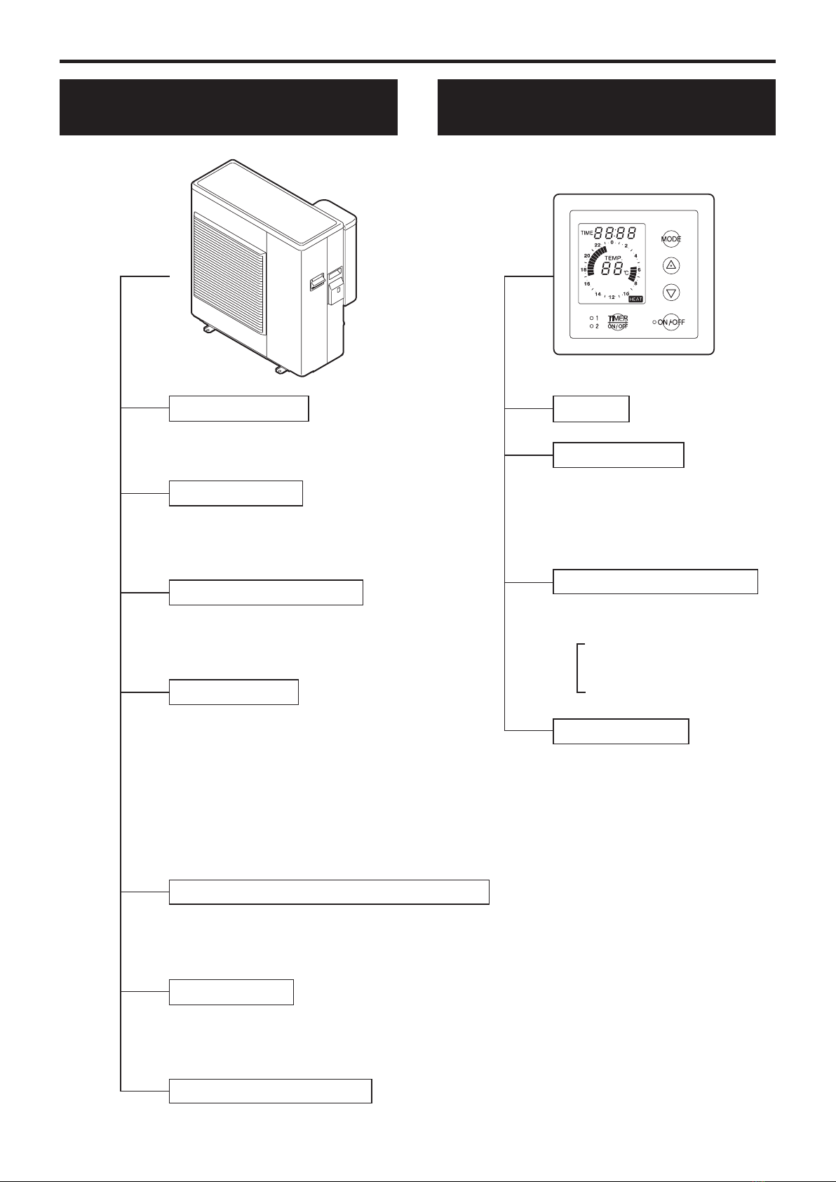
UNIT
APPEARANCE, PORTION, PARTS SEEMED WRONG
check the power supply
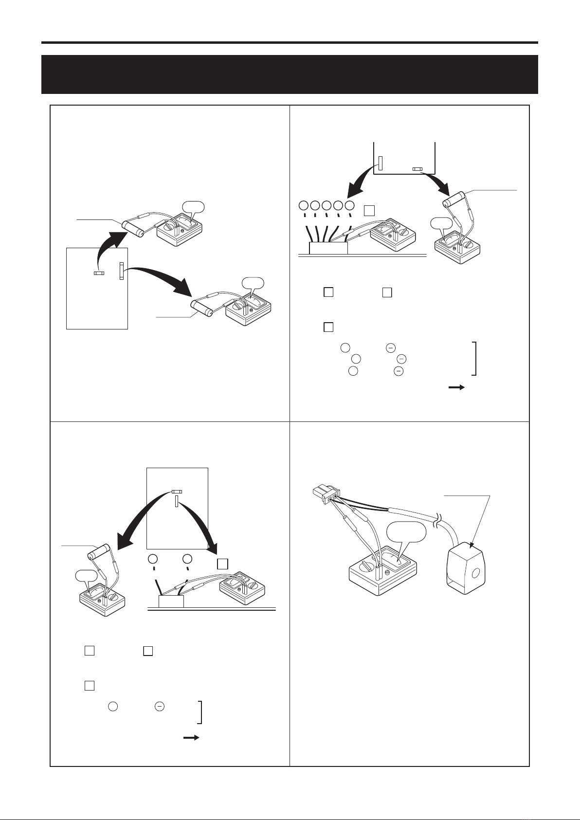
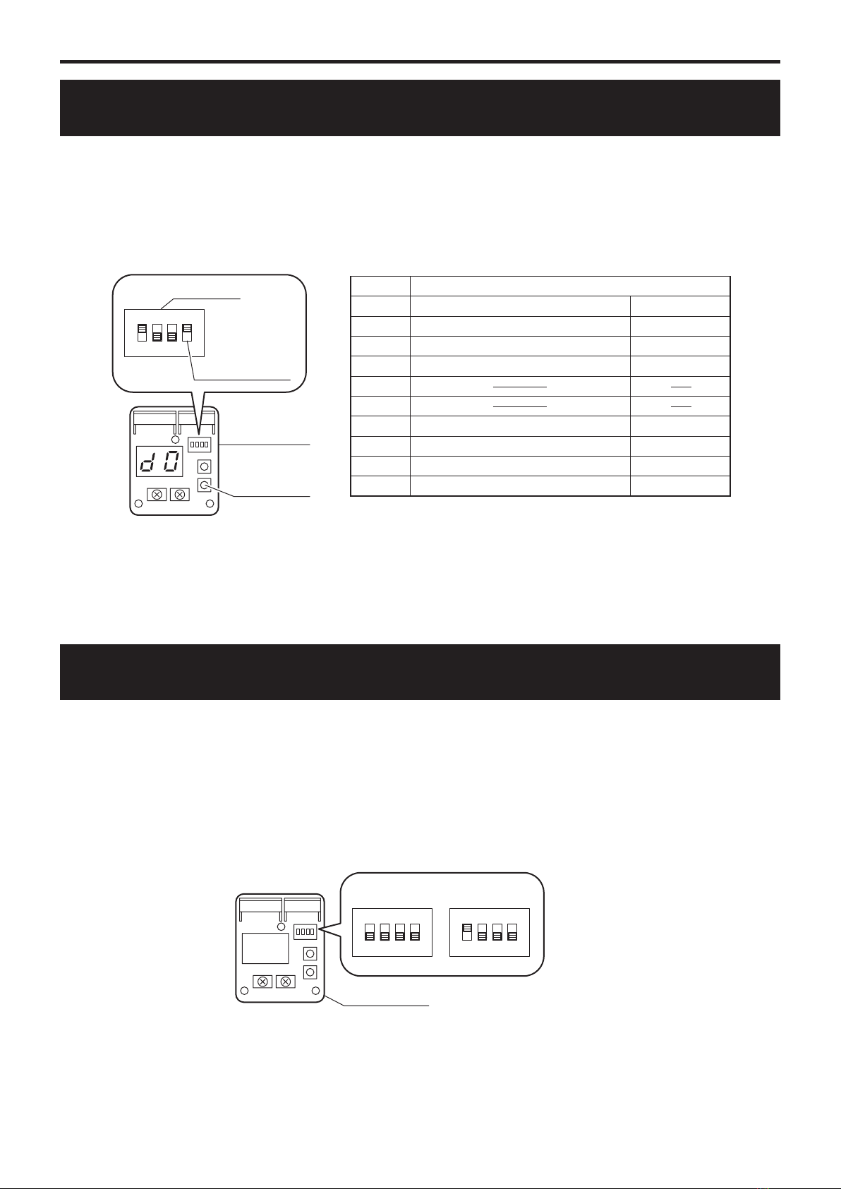
check the electric continuity by tester [see g. 1]
METHOD OF CHECK
POWER SUPPLY
FUSE CF3 (250V T5A)
check the electric continuity by tester [see g. 1]FUSE CF1 (250V T25A)
FUSE CF4 (250V T3.15A)
FAN MOTOR
PCB (CONTROLLER) PCB (CONTROLLER) should be replaced
accident of
FAN MOTOR
C3
(*1)
accident of dischage
temperature check the service valve and refrigerant circuit (pipe)
check the resistance by tester [see table 1]
check the resistance by tester [see table 2]
CT disconnection
accident of SENSOR
accident of SENSOR
accident of SENSOR
accident of SENSOR
change the PCB (CONTROLLER)
protective action
against excess
current AC current
detection
check the power voltage (230V)
check the movement by reoperation
POWER MODULE should be replaced
check the resistance by tester [see table 1]
check the resistance by tester [see table 1]
check the resistance by tester [see table 1]
check the resistance by tester [see table 2]
rise of temperature
(above 110°C)
of POWER MODULE
accident of SENSOR
check the place of installation (blockage of air inlet & outlet)
GAS LEAKAGE
check the place of installation (blockage of air inlet & outlet )
check the excess gas
UNREASONABLE OPERATION
UNDER OVERLOAD
PCB (CONTROLLER)
DROP OF POWER VOLTAGE
MOMENTARY STOP OF POWER
(IN CASE OF LIGHTNING)
SENSOR, TEMP. POWER MODULE
SENSOR, TEMP. OUTDOOR
MIS-INSTALLATION
SENSOR, TEMP. SUCTION
SENSOR, TEMP. DEFROST
SENSOR, TEMP. DISCHARGE
A6
A1
A3
A4
A7
A8
C2
C4
C5
C6
accident of
POWER MODULE POWER MODULE POWER MODULE should be replacedC0
accident of DC voltage
FAN MOTOR
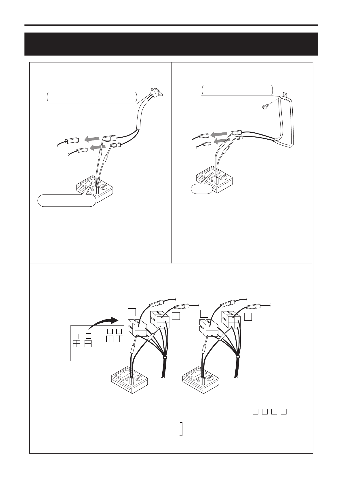
A0 POWER MODULE take o the terminals (orange and blue) and check the resistance between orange-blue
if the resistance is over 100kΩ, POWER MODULE is normal
POWER SUPPLY check the power supply
(*1) When checking fan motor and/or pump, turn o the power supply completely and tatch their terminal or connector
check the electric continuity FUSE CF4 (250V T3.15A) by tester
if it is continuity, check the voltage of FAN MOTOR
if the voltage is nomal, FAN MOTOR should be replaced [see g. 2]
POWER MODULE should be replaced
take o the connector 9 , and check the resistance between red-black in the connector
if the resistance is over 100kΩ, FAN MOTER is normal
SENSOR, TEMP. POWER MODULE
accident of
PCB (CONTROLLER) PCB (CONTROLLER)
SENSOR, TEMP. SUCTION
SENSOR, TEMP. DISCHARGE
abnormal revolution
of compressor
A5
POWER MODULE
protective action
against excess
current DC current
detection
check the place of installation (blockage of air inlet & outlet )
check the excess gas
check the power voltage (230V)
UNREASONABLE OPERATION
UNDER OVERLOAD
DROP OF POWER VOLTAGE
FUSE CF2 (250V T15A)
other than described above
check the electric continuity FUSE CF2 (250V T15A) by tester
A2 POWER MODULE
COMPRESSOR
PCB (CONTROLLER) should be replaced
operate without the junction connector of compressor lead wire
if the error code is same, POWER MODULE should be replaced
check the place of installation (blockage of air inlet & outlet )
check the excess gas
check the power voltage (230V)
UNREASONABLE OPERATION
UNDER OVERLOAD
DROP OF POWER VOLTAGE
FUSE CF2 (250V T15A) check the electric continuity FUSE CF2 (250V T15A) by tester
COMPRESSOR other than described above
check the resistance of POWER MODULE by tester
take off the junction connector of compressor lead wire
measure resistance between the connector pins of junction connector,
six times between white-black, black-red, red-white respectively by changing the polarity
if all the figures show over 100kΩ, POWER MODULE is normal
Inverter PCB serial error
CONNECTOR 13 is RARE CONTACT or
POWER MODULE and PCB(CONTR-
OLLER)
Turn o the power supply , wait for about 3 minutes
take o and insert the connector 13 , and then power up again
POWER MODULE or PCB(CONTROLLER) should be replaced
C8