CHOFU AEYC-1639U-CH Quick guide

MADE IN JAPAN
AIR TO WATER HEAT PUMP
HEATING AND COOLING
MONOBLOC TYPE
DC INVERTER
INSTALLATION AND INSTRUCTION MANUAL
KEEP THIS MANUAL FOR FUTURE REFERENCE
GB
AEYC-0639U-CH
AEYC-1039U-CH
AEYC-1639U-CH

2
1. Responsibility and recommendations ......... 3
2. Specications........................................... 8
3. Installation ............................................... 9
3.1 Notice for safety installation
3.2 Positioning and securing
3.3 Main components
3.4 Pressures and quantity available at heat pump outlet
3.5 Water circuit connection
3.6 Electrical connections
3.7 Remote controller
4. Remote controller..................................... 26
4.1 Buttons
4.2 Display panel
5. Operation and functions
of the Remote controller............................ 28
5.1 System ON/OFF
5.2 Setting the day and time
5.3 Selecting the operating mode
5.4 Domestic Hot Water production
5.5 Setting the time bands for Heating/Cooling
5.6 Setting the time bands for DHW, Low tariff and Night mode
5.7 Procedure for accessing the Parameter setting menu
6. Electrical connections ............................... 49
6.1 PCB(Terminal)
6.2 PCB(Terminal) Input/Output
6.3 Parameters Input/Output
7. Unit Management..................................... 53
7.1 Operating modes
7.1.1 Select mode from user interface
7.1.2 Select mode by remote contact
7.2 Water temperature set point
7.2.1 Fixed set point
7.2.2 Climatic curve
7.2.2.1 Heating Climatic curves
7.2.2.2 Cooling Climatic curves
7.2.3
Additional Outdoor air temperature probe for Climatic
curves
7.2.4 Buffer tank temperature probe
7.2.5 HP unit control
7.2.5.1
HP unit controlled based on Outgoing water temperature
7.2.5.2
HP unit controlled based on Outgoing water temperature
and Room air temperature
7.2.5.3 HP unit controlled based on Buffer tank temperature
7.2.5.4 HP unit controlled based on Buffer tank temperature
and Room air temperature
7.2.5.5 HP unit controlled based on DHW tank temperature
7.3 Water pump management
7.3.1 Main water pump
7.3.1.1 Continuous operation “Always ON”
7.3.1.2 Snifng operation “Snifng cycle”
7.3.1.3 Unlock pump function
7.3.1.4 Pump output adjustment function
7.4 Frost protection
7.4.1 Frost protection based on Room air temperature
7.4.2 Frost protection based on Outdoor air temperature
7.4.3 Frost protection based on Outgoing water temperature
7.4.4 DHW tank frost protection
7.4.5 Secondary system circuit frost protection
7.5 Input/Output contact
7.5.1 Heating/Cooling mode remote contact
7.5.2 ON/OFF DHW production remote contact
7.5.3 ON/OFF remote contact
7.5.4 EHS Alarm
7.5.5 Flow switch
7.5.6 Dual set point control
7.5.7 Additional water pump
7.5.7.1 Additional water pump1
7.5.7.2 Additional water pump2
7.5.8 Heating/Cooling mode output
7.5.9 Congurable contact (Alarm)
7.5.9.1 Alarm
7.5.9.2 Ambient temperature reached
7.5.10 Night mode
7.5.11 Low tariff
7.5.12 Dehumidier management
7.5.13 Space Heating management
8. Domestic Hot Water Production................. 98
8.1 DHW 3way valve management
8.1.1 Max time for DHW request
8.1.2 DHW 3way valve change over time
8.2 DHW production mode
8.2.1 Heat pump only
8.2.2 DHW Electric heater only
8.2.3 Heat pump + DHW heater
8.2.4 Legionella prevention function
8.3 Backup heater
8.3.1 Backup heater in Replacement mode
8.3.2 Backup heater in Supplementary mode
8.3.3 Freeze protection function
8.4 EHS (External heat source)
8.4.1 EHS in Replacement mode
8.4.2 EHS in Supplementary mode
9. Parameter List .........................................
124
9.1 Access limitation
9.2 Parameter table
10. Installation check and Test operation........
138
10.1 Installation check
10.2 Test operation
11. Service and Maintenance ........................
140
11.1 Error code display
11.2 Error history display
11.3 Method of reset error code display
11.4 List of Error codes
11.5 Check and troubleshooting
11.6 Monitor display function
11.7 Maintenance
Index

3
1. Responsibility and recommendations
General Information
• Carefully read this manual and keep it for future reference.
• Carefully evaluate the potential risks before carrying out any repair or
maintenance, and take the necessary precautions to guarantee personal safety.
• Do not attempt to repair, move or re-install the unit without the help of a qualied
technician.
Responsibility
The manufacturer declines every responsibility and declares the warranty on the
unit void in the event of damages caused by:
• Incorrect installation, including noncompliance with the instructions contained in
the relative manuals.
• Modications or errors in the electric or cooling or hydraulic connections.
• Unauthorised coupling of other units, including units from other manufacturers.
• Use of the unit in conditions different to those indicated.
All materials used for manufacturing and packaging of the new equipment
are ecological and or recyclable.
Directive 2002/96/EC (WEEE): Information for the users
This product is in compliance with the EU 2002/96/EC Directive.
The symbol of the crossed bin on the appliance indicates that the product, at the
end of its life span, must be treated separately from household waste. It must be
taken to a differentiated collection centre for electric and electronic appliances or
taken back to the supplier on the purchase of a new equivalent appliance.
The user is responsible for taking the appliance to an appropriate collection centre
at the end of its life span. Disposing of a household appliance separately avoids
possible negative consequences for the environment and health deriving from
inappropriate disposal and enables the constituent materials to be recovered to
obtain signicant savings in energy and resources.
For more detailed information regarding the collection systems available, contact
the local waste disposal service or the supplier where the purchase was made.
4
1. Responsibility and recommendations
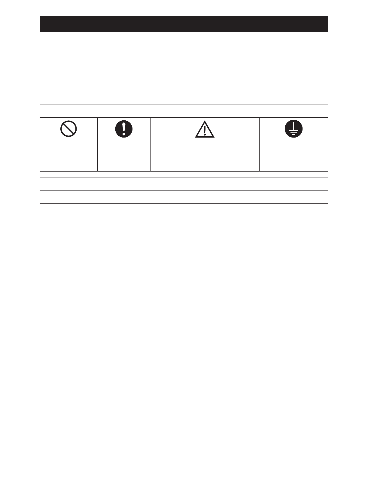
MEANING OF THE SYMBOLS
Indicates
PROHIBITION
Indicates
OBLIGATION
Indicates
PRECAUTION
(also dangerous/warnings)
CONNECT THE
GROUND CABLE
MEANING OF THE INDICATION
DANGER ATTENTION
Indicates the risk of death or
serious injuries in the event of
misuse.
Indicates the risk of personal injury or
damage to property, furniture or animals in
the event of failure to follow the instructions.
Important information on safety is reported on the product and contained in this
Manual. Carefully read this installation manual before installing the unit. Important
information for correct installation is contained in the Manual.
Safety procedures
5
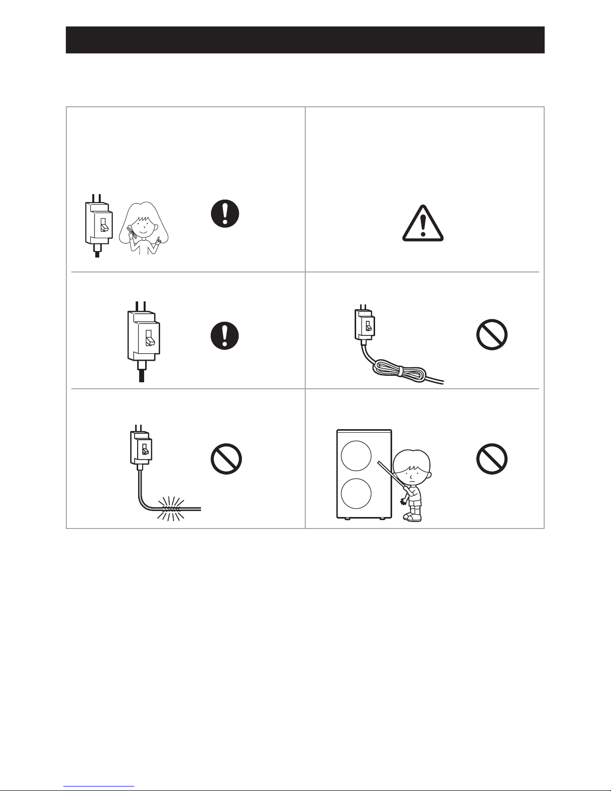
1. Responsibility and recommendations
Use the voltage 230V. Do not use the power supply
cable in a bundle.
Take care not to damage the
power supply cable.
Do not insert objects into the air
inlet or outlet.
GB
Prohibition
1
2
MODE
ON
/
OFF
TIMER
ON
/
OFF
CAUTION
Strict
Enforcement
Prohibition Prohibition
Prohibition Prohibition
Prohibition
GB
Prohibition
1
2
MODE
ON
/
OFF
TIMER
ON
/
OFF
CAUTION
Strict
Enforcement
Prohibition Prohibition
Prohibition Prohibition
Prohibition
GB
Prohibition
1
2
MODE
ON
/
OFF
TIMER
ON
/
OFF
CAUTION
Strict
Enforcement
Prohibition Prohibition
Prohibition Prohibition
Prohibition
When an anomaly is detected, as
a burning smell, immediately stop
the power supply by isolating on
the main switch of the electrical
panel.
This unit must not be used by
children or people with reduced
physical, sensory or mental
capabilities, or lack of experience
and knowledge, unless they are
supervised.
GB
Prohibition
1
2
MODE
ON
/
OFF
TIMER
ON
/
OFF
CAUTION
Strict
Enforcement
Prohibition Prohibition
Prohibition Prohibition
Prohibition
PROHIBITION
GB
Prohibition
1
2
MODE
ON
/
OFF
TIMER
ON
/
OFF
CAUTION
Strict
Enforcement
Prohibition Prohibition
Prohibition Prohibition
Prohibition
PROHIBITION
STRICT
ENFORCEMENT
GB
Prohibition
1
2
MODE
ON
/
OFF
TIMER
ON
/
OFF
CAUTION
Strict
Enforcement
Prohibition Prohibition
Prohibition Prohibition
Prohibition
GB
Prohibition
1
2
MODE
ON
/
OFF
TIMER
ON
/
OFF
CAUTION
Strict
Enforcement
Prohibition Prohibition
Prohibition Prohibition
Prohibition
GB
Prohibition
1
2
MODE
ON
/
OFF
TIMER
ON
/
OFF
CAUTION
Strict
Enforcement
Prohibition Prohibition
Prohibition Prohibition
Prohibition
PROHIBITION
CAUTION

6
1. Responsibility and recommendations
-
Prohibition
STRICT
ENFORCEMENT
Prohibition Prohibition
Prohibition
Prohibition Prohibition
Prohibition
Hight temperature
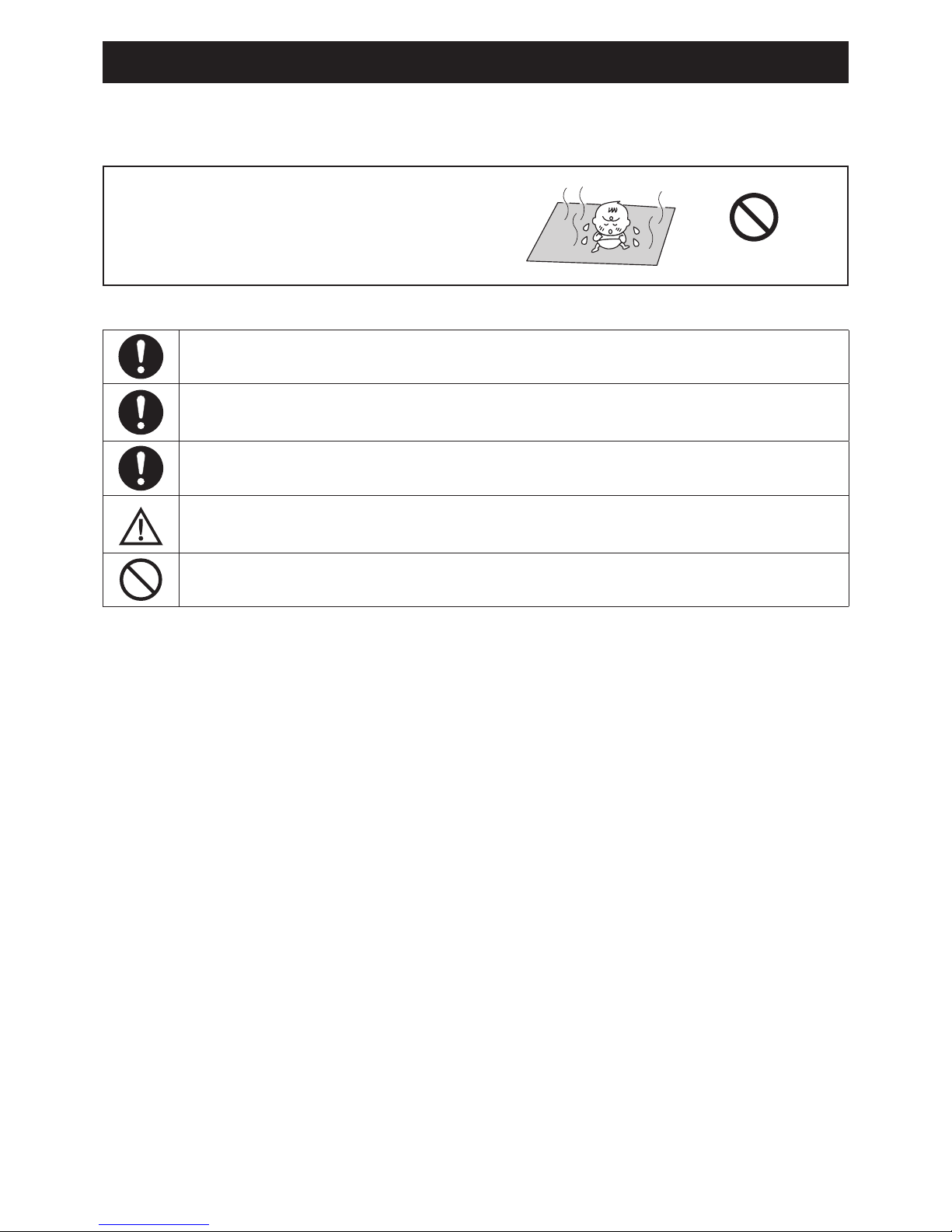
Connect the earth wire. Use an exclusive power source
with a circuit breaker.
Do not install the unit in the
place with any possibility of
inammable gas leakage around
the unit.
Do not allow the unit to be
exposed to vapor or oil steam.
Do not stop the operation
by turning off the circuit breaker.
Check good condition
of the installation stand.
Do not pour water into the unit
for cleaning.
Do not place animals or plants
in the direct path of the air ow.
-
Prohibition
STRICT
ENFORCEMENT
Prohibition Prohibition
Prohibition
Prohibition Prohibition
Prohibition
Hight temperature
-
Prohibition
STRICT
ENFORCEMENT
Prohibition Prohibition
Prohibition
Prohibition Prohibition
Prohibition
Hight temperature
Do not place any objects
on or climb on the unit.
Note for draining water.
The maximum temperature for the circulating
water is approximately 60°C. Take care to
avoid burns when draining the water.
-
Prohibition
STRICT
ENFORCEMENT
Prohibition Prohibition
Prohibition
Prohibition Prohibition
Prohibition
Hight temperature
HIGH TEMPERATURE
Do not try to repair or
reconstruct by yourself.
Do not extend power supply cable
or connect incorrectly.
GB
Prohibition
1
2
MODE
ON
/
OFF
TIMER
ON
/
OFF
CAUTION
Strict
Enforcement
Prohibition Prohibition
Prohibition Prohibition
Prohibition
PROHIBITION
GB
Prohibition
1
2
MODE
ON
/
OFF
TIMER
ON
/
OFF
CAUTION
Strict
Enforcement
Prohibition Prohibition
Prohibition Prohibition
Prohibition
PROHIBITION
GB
Prohibition
1
2
MODE
ON
/
OFF
TIMER
ON
/
OFF
CAUTION
Strict
Enforcement
Prohibition Prohibition
Prohibition Prohibition
Prohibition
PROHIBITION
GB
Prohibition
1
2
MODE
ON
/
OFF
TIMER
ON
/
OFF
CAUTION
Strict
Enforcement
Prohibition Prohibition
Prohibition Prohibition
Prohibition
PROHIBITION
GB
Prohibition
1
2
MODE
ON
/
OFF
TIMER
ON
/
OFF
CAUTION
Strict
Enforcement
Prohibition Prohibition
Prohibition Prohibition
Prohibition
PROHIBITION
GB
Prohibition
1
2
MODE
ON
/
OFF
TIMER
ON
/
OFF
CAUTION
Strict
Enforcement
Prohibition Prohibition
Prohibition Prohibition
Prohibition
PROHIBITION
GB
Prohibition
1
2
MODE
ON
/
OFF
TIMER
ON
/
OFF
CAUTION
Strict
Enforcement
Prohibition Prohibition
Prohibition Prohibition
Prohibition
PROHIBITION
GB
Prohibition
1
2
MODE
ON
/
OFF
TIMER
ON
/
OFF
CAUTION
Strict
Enforcement
Prohibition Prohibition
Prohibition Prohibition
Prohibition
PROHIBITION
GB
Prohibition
1
2
MODE
ON
/
OFF
TIMER
ON
/
OFF
CAUTION
Strict
Enforcement
Prohibition Prohibition
Prohibition Prohibition
Prohibition
PROHIBITION
STRICT
ENFORCEMENT
7
1. Responsibility and recommendations
GB
Prohibition
1
2
MODE
ON
/
OFF
TIMER
ON
/
OFF
CAUTION
Strict
Enforcement
Prohibition Prohibition
Prohibition Prohibition
Prohibition
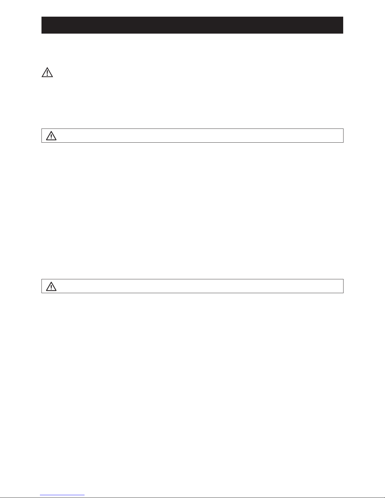
If the same part of the body is
exposed to the oor heating for
a long time, it could cause low
temperature scalding.
GB
Prohibition
1
2
MODE
ON
/
OFF
TIMER
ON
/
OFF
CAUTION
Strict
Enforcement
Prohibition Prohibition
Prohibition Prohibition
Prohibition
PROHIBITION
Check personnel wears suitable personal protective equipment.
Verify the absence of damages caused by transport or movement of the
equipment and, immediately forward the claim to the supplier.
Dispose of the packing material in compliance with the local standards.
Do not lift the unit by inserting hooks in the side handles but use specic
equipment (lifting devices, trucks, etc.).
Do not rest liquid containers or other objects on the unit.
• Do not use this unit for any purposes other than Heating and Cooling.
• This appliance can be used by children aged from 8 years and above and persons
with reduced physical, sensory or mental capabilities or lack of experience and
knowledge if they have been given supervision or instruction concerning use of
the appliance in a safe way and understand the hazards involved. Children shall
not play with the appliance. Cleaning and user maintenance shall not be made by
children without supervision.
• The appliance is accessible to the general public.

8
1.2. Specications
Model
AEYC-0639U-CH AEYC-1039U-CH AEYC-1639U-CH
Type Heating and Cooling Monobloc Type
DC Inverter (Reverse cycle)
Power 1N ~ 230V 50Hz
Heating (*)
Capacity [kW] 6.0 10.0 16.0
Power Input [kW] 1.46 2.30 3.90
Running Current (MAX.) [A] 6.4(11.2) 10.2(17.5) 17.0(25.3)
COP 4.11 4.35 4.10
Cooling (*)
Capacity [kW] 5.0 8.0 16.0
Power Input [kW] 1.28 2.32 4.10
Running Current (MAX.) [A] 5.6(6.6) 10.1(11.6) 17.8(23.0)
EER 3.91 3.45 3.90
MAX. Pressure [MPa] 4.1
Refrigerant (R410A) [kg] 1.05 1.72 2.99
Dimentions & Weight (NET)
Height [mm] 675 882 1,418
Width [mm] 825 850 1,000
Depth [mm] 300 330 330
Weight [kg] 52 74 119
Temperature Range
Outdoor Temperature
Heating [°C] –20 to 43
Cooling [°C] 18 to 43 20 to 43 15 to 43
Inlet Water Temperature [°C] 18 to 55
Water Pressure [MPa] 0.1 to 0.3
• Specications are subject to change without notice.
(*) Rating condition Heating : Outdoor temperature DB/WB 7°C/6°C, Leaving water temperature 35°C
Cooling : Outdoor temperature 35°C, Leaving water temperature 18°C
• Acoustic Noise Information : The maximum sound pressure level is less than 70 dB (A).
According to IEC 704-1 and ISO 3744.
• If the air to water heat pump is operated under higher temperature conditions than those listed, the built-in protection circuit
may operate to prevent internal circuit damage. Also, during Cooling modes, if the unit is used under conditions of lower
temperatures than those listed above, it may freeze, leading to water leakage and other damage.

9
3. Installation
3.1 Notice for safety installation
CAUTION
• Please ask qualied installer to install this unit.
• Do not attempt to install this unit by yourself to avoid accidents such as electric shock, re and leakage of water.
• Before installing this unit, please read this notice for safety installation carefully and install properly and safely.
• Be sure to follow the safety articles mention of important details on safety.
• After nishing the installation, please check no defective points in the testing operation. Then, kindly explain to
the user about the directions and maintenance according to the operation manual.
• For product modication, the product and its specication may show slight differences from the description of this manual.
DANGER
• Be sure to install the unit in suitable place to hold the heavy weight. Lack of stability or imperfect installation may
cause injury due to the fall unit falling.
• Do not install to a place where there is any possibility of inammable gas leakage such as from LP gas cylinder
around the unit. Leaked inammable gas around the unit may cause a re.
• If the leaked refrigerant is exposed to re, poisonous gas may be generated.
• The entry of other gases, such as air, into the cooling circuit could cause an explosion and injuries.
WARNING
• At the time of installation of the unit or relocation, use only the designated refrigerant (R-410A) into refrigerant
circulating system (Refrigeration circuit). Other gas such as air in the refrigeration circuit may cause an explosion
and injury.
• Connect the unit with standard parts required. This installation manual describes the correct connections using
the installation set available from standard parts.
DANGER
• Installation work must be performed in accordance with national wiring standards by authorized personnel only.
• For the air to water heat pump to operate satisfactorily, install it as outlined in this installation manual.
• Also, do not use an extension cord.
• Do not turn on the power until all installation work is complete.
• Use designated parts or accessories to avoid accidents such as electric shock, re and leakage of water.
• Follow the local standards in electric works. Be sure to use an exclusive power source.
• Any shortage of electric circuit’s capacity or imperfect works may cause an electric shock and a re.
• Never touch electrical components immediately after the power supply has been turned off. Electrical shock may
occur. After turning off the power, always wait 5 minutes or more before touching electrical components.
• Be sure to x the power supply cable in connecting points of the terminal block correctly, Imperfection of the
connecting may cause overheating and a re.
• Be sure to install the wiring lid in a straight line. Imperfect wiring works may cause overheating, a re or electric
shock at the connecting point in the terminal block.
• Always connect earth wire.
Never connect the earth cable to gas tube, water supply pipes, lightning rod and earth cable of telephone.
Imperfect earth connection may cause electric shock.
• Install a circuit breaker. Lack of circuit breaker may cause electric shock.
CAUTION
• Be sure to complete a drainage works according to this manual.
• After installation, check that there are no defects in the test. Then kindly inform the user about instructions and
maintenance according to the user manual.

10
3. Installation
Minimum clearanceDimensions
3.2 Positioning and securing
327
57
388 54
R3/4(20A)
30015.3 42
825 73
675
580
122.5 122.5
43
Circulating water
return port
Circulating water
outgoing port
AEYC-0639U-CH
• Anchor the unit to the concrete with bolts (ø10 mm) and nuts rmly and level.
• In case the vibration may affect the house, use an anti-vibration mounts and x the unit securely.
Over 300mm
Over 600 mm
Over 100mm
Over 100mm
Over 600mm
AEYC-1039U-CH
882
850 24
R1(25A)
R1(25A)
25 330 38
480173
155540155
75 70
357
Circulating water
return port
Circulating water
outgoing port
AEYC-1039U-CH
Over 300mm
Over 600 mm
Over 100mm
Over 100mm
Over 600mm
AEYC-1639U-CH
680185
357
80 80
241000 3637 330
1418
205590205
Circulating water
outgoing port
Circulating water
return port
R1 1/4(32A)
R1 1/4(32A)
AEYC-1639U-CH
Over 300mm
Over 600 mm
Over 100mm
Over 100mm
Over 600mm
AEYC-0639U-CH
(Unit:mm)
11
3. Installation
SELECTION ON THE PLACE
• Consider a place where the noise and the air discharged to not affect neighbours.
• Consider a position protected from the wind.
• Consider an area that respects the minimum spaces recommended.
• Consider a place that does not obstruct the access to doors or corridors.
• The surfaces of the oor must be solid enough to support the weight of the unit and minimise the transmission of
vibrations.
DANGER
• Do not install where there is the danger of combustible gas leakage.
• If children may approach the unit, take preventive measures so that they cannot reach the unit.
• Install the unit in a place where it will not be inclined more than 5 °.
When installing the unit where it may exposed to strong wind, brace it securely.
Decide the mounting position with the customer as follows:
(1) Install the unit in a location which can withstand the weight of the unit and vibration. Please make sure it is
installed level.
(2) Provide the indicated space to ensure good airow.
(3) Do not install the unit near a source of heat, steam, or ammable gas.
(4) During heating operation, condensate water ows from the unit. Therefore, install the unit in a place where the
condensate water ow will not be obstructed.
(5) Do not install the unit where strong wind blows or where it is very dusty.
(6) Do not install the unit where people pass.
(7) Install the unit in a place where it will be free from being dirty or getting wet by rain as much as possible.
CAUTION
• When the outdoor temperature is 0°C or less, remove the drain pipe and use without it. If the drain pipe is used,
the drain water in the pipe may freeze in extremely cold weather.
• In the area with heavy snowfall, if the intake and outlet of unit is blocked with snow, it might become difcult to get
warm and it is likely to cause of the breakdown. Please construct a canopy and a pedestal or place the unit on a
high stand.
12
3. Installation
Air inlet is located in the left or in the back
Air inlet is located in the left or in the back
Air inlet is located in the left or in the back
Air outlet
Air outlet
Air outlet
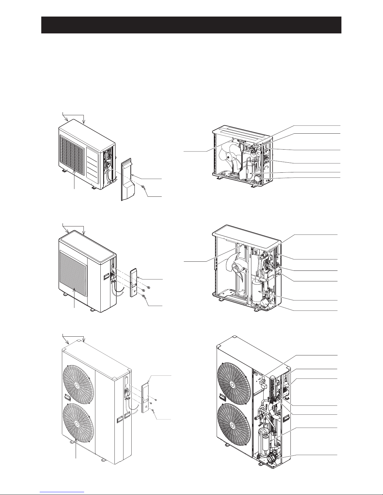
The heat pump has various safety parts and an internal circulator (Pump1) for quick installation with the aid of a
few external components.
3.3 Main components
Wiring lid
Screw
AEYC-0639U-CH
AEYC-1039U-CH
AEYC-1639U-CH
PCB(Terminal)
Airpurge valve
Terminal block
Pump
Compressor
Pressure relief valve
PCB(Main)
Wiring lid
Screw
PCB(Terminal)
Airpurge valve
Terminal block
Pump
Compressor
Pressure relief valve
PCB(Main)
Wiringlid
Screw
PCB (Main)
PCB (Terminal)
Terminal block
Airpurge valve
Pump
Compressor
Pressure relief valve
13
3. Installation
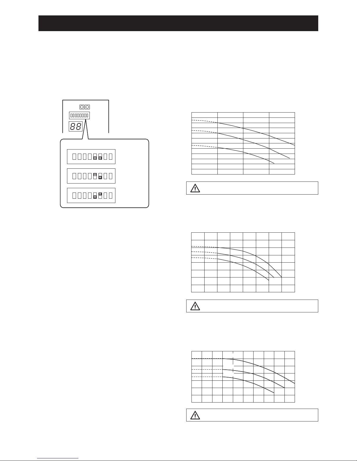
3.4 Pressures and quantity available at heat pump outlet
Main water pump in the unit has 3 levels of speed.
Factory default value is level 3.
Select dip switch 5 and 6 of DIP SW. on PCB(Terminal) to change the setting.
ON
4321 65 87
OFF
DIP SW.
Level 3
(Maximum)
ON
4321 65 87
OFF
Level 2
(Medium)
ON
4321 65 87
OFF
Level 1
(Minimum)
CAUTION
The quantity should not be less than 15L/min.
0
2
4
6
8
10
12
14
(m)
0 10 20 30 40
Level3
Level2
Level1
50(L/min)
AEYC-1639U
0
2
4
6
8
10
12
14
(m)
0 10 20 30 40
Level3
Level2
Level1
50(L/min)
0
1
2
3
4
5
6
7
8
(m)
0 105 20
15 25 30 35 40(L/min)
Level3
Level2
Level1
CAUTION
The quantity should not be less than 10L/min.
AEYC-1039U
0
1
2
3
4
5
6
7
8
9
10
11
12
(m)
0 5 10 15 20(L/min)
Level3
Level2
Level1
CAUTION
The quantity should not be less than 5L/min.
AEYC-0639U
14
3. Installation
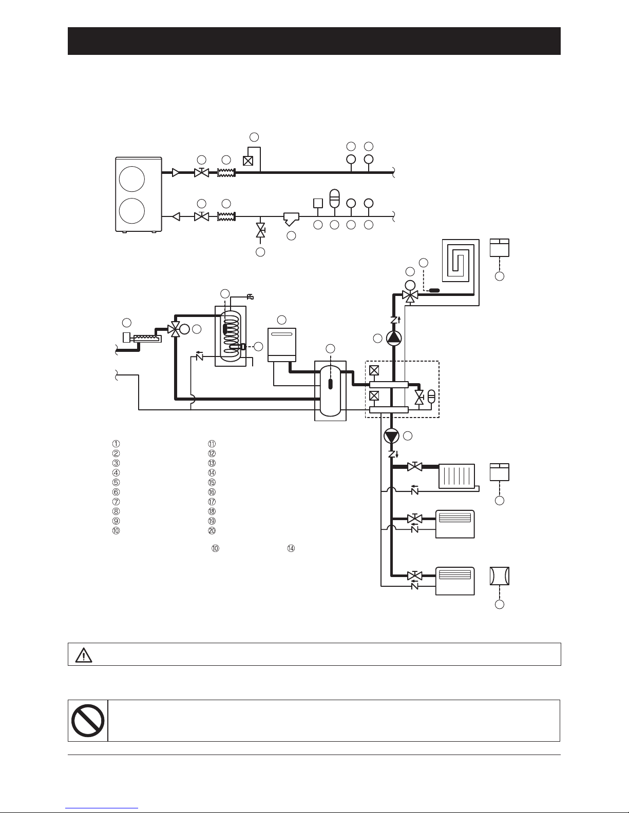
Do not use the heat pump to treat industrial process water, swimming pool water or domestic water.
Set-up an intermediate heat exchanger for all the above cases.
CAUTION
• The quantity of water in the system must not be less than 30 litres
• If the quantity of water in the system is higher than 160 litres, use an additional Buffer tank
3.5 Water circuit connection
Buffer tank
Mani fold
Outlet
Inlet
DHW tank
M
Space Heating
Dehumidifier
M
Fan convector
Radiant panel
F P T
PT
12
12
3
89
89
6
5
7
4
11
13
14
12
10
15
19
17
18
16
16
19
20
Shut-off valve
Vibration damper joint
Air bleed valve
Fill/drain valve
Water line filter
Flow switch
Expansion vessel
Pressure gauge
Thermometer
Backup heater*
DHW 3way valve
DHW tank temperature probe
DHW Electric heater
EHS*
Buffer tank temperature probe
Additional water pump
Mixing valve
Mix water temperature probe
Remote controller
Humidity sensor
* Backup heater and EHS
cannot be used at same time.
HP unit
15
3. Installation
The hydraulic connections of heat pump 01, must be carried out using all necessary components and completed
with materials able to guarantee water seal of the threaded joints. The diagram typical of hydraulic circuit shows
applications in the air conditioning eld.
The hydraulic circuit must be completed following the recommendations below:
1. It is advised to include shut-off valves allowing isolation of the most important components of the system.
These valves, that can be ball, globe or buttery, must be dimensioned to allow the smallest load loss,
possible when in opening position.
2. The system must have drainage in the lowest points.
3. Air vents must be included in the highest points of the system.
4. Gauges and pressure couplings must be installed upstream and downstream of the pump.
5. All piping must be adequately insulated and supported.
6. The presence of solid particles in the water can obstruct the heater. Therefore, protect the exchanger using a
removable mesh lter. The gauge of the lter net must be of at least 10 meshes/cm2.
7. After system assembly ush and clean the whole system, paying particular attention to the state of the lter.
8. In cases where water must be cooled at temperatures below 5°C, of if the device is installed in areas subject to
temperatures below 0°C, it is essential to mix water with an adequate amount of monoethylene glycol inhibitor.
9. In the event of new installation or emptying of the circuit, preventively clean the system. In order to guarantee
good product operation, after every cleaning operation, water replacement or glycol addition, check the liquid is
clear, without visible impurities and the hardness is below 20°.
% Monoethylene glycol inhibitor 10% 20% 30% 40%
Freezing temperature * -4°C -9°C -15°C -23°C
Correction factor
Capacity 0,996 0,991 0,983 0,974
Power absorbed 0,990 0,978 0,964 1,008
Pressure drop 1,003 1,010 1,020 1,033
(*) The temperature values are indicative. Always refer to the temperatures given for the specic product used.
Hydraulic connections
Anti-freeze concentration in the system

16
3. Installation
Connection to the water circuit
1) Connect the water supply to a drain and ll valve.
2) Loosen the plug a little to take the air out of the circulating water pipe through the air purge valve. The plug
doesn't have to be removed. Be careful not to loose it.
3) Fill with water until the manometer indicates a pressure of approximately 2.0 bar. Remove air in the circuit as
much as possible using the air purge valves.
4) After the air is all purged from the system, tighten the plug again.
• Water connections must be made in accordance with diagram in the manual and on the unit, respecting the water
in-and outlet.
CAUTION
• Be careful not to deform the unit piping by using excessive force when connecting. Deformation of the piping can
cause the unit to malfunction.
If air, moisture or dust gets in the water circuit, problems may occur. Therefore, always take into account the
following when connecting the water circuit:
• Use clean pipes only.
• Hold the pipe end downwards when removing burrs.
• Cover the pipe end when inserting it through a wall so that no dust and dirt enter.
• Use a good thread sealant for the sealing of the connections. The sealant must be able to withstand the
pressures and temperatures of the system.
• When using non-brass metallic piping, make sure to insulate both materials from each other to prevent galvanic
corrosion.
• Because brass is a soft material, use appropriate tooling for connecting the water circuit. Inappropriate tooling will
cause damage to the pipes.
• The unit is the only to be used in a closed water system. Application in an open water circuit can lead to
excessive corrosion of the water piping.
Before continuing the installation of the unit, check the following points:
• The maximum water pressure is 3 bar.
• Make sure to provide a proper drain for the pressure relief valve to avoid any water coming into contact with
electrical parts.
• Air vents must be provided at all high points of the system. The vents should be located at points which are easily
accessible for servicing. An automatic air purge is provided inside the unit. Check that this air purge valve is not
tightened too much so that automatic release of air in the water circuit remains possible .
• Take care that the components installed in the eld piping can withstand the water pressure.
• Never use Zn-coated parts in the water circuit. Excessive corrosion of these parts may occur as copper piping is
used in the unit’s internal water circuit.
loosen
tighten
Air purge valve
Plug
Charging water

17
3. Installation
Piping insulation
The complete water circuit, including all piping, must be insulated to prevent condensation during cooling operation
and reduction of the cooling and heating capacity.
If the temperature is higher than 30°C and the humidity is higher than RH 80%, then the thickness of the sealing
materials should be at least 20 mm in order to avoid condensation on the surface of the sealing.
Be sure to insulate the pipes in order to prevent the water being frozen.
Anti-freeze function setting
PCB(Terminal)
ON
4321 65 87
OFF
DIP SW. position
If the circulation water is mixed with a certain quantity of inhibited monoethylene glycol, then the anti-freeze
function is not necessary.
To disable the anti-freeze function, access the PCB (Terminal) and set “Dip SW1” to OFF.
Remove the wiring lid to access the PCB (Terminal).
“Dip SW1” factory default setting is ON, so the anti-freeze function is enabled.
When Pump SW on the PCB (Terminal) is pressed, the water pump comes into operation to circulate water.
Each digital segment on the right side of the PCB (Terminal) lights up sequentially during pump operation.
The pump is stopped automatically after 10 minutes of operation. If air could not be released this way from the
water circuit, then press Pump SW again after the pump has stopped. If you want to stop the pump before it stops
automatically, press Pump SW again.
Display
Pump SW.
Water loading and air bleeding in the hydraulic circuit
• During lling, it might not be possible to remove all air in the system. Remaining air will be removed through the
automatic air purge valves during rst operating hours of the system. Additional lling with water afterwards might
be required.
• The water pressure indicated on the manometer will vary depending on the water temperature (higher pressure at
higher water temperature).
However, at all times water pressure should remain above 0.3 bar to avoid air entering the circuit.
• The unit might dispose some excessive water through the pressure relief valve.
• Water quality must be according to EN directive 98/83 EC.
NOTICE

18
3. Installation
• In case of using the drain elbow, attach it as illustrated.
• Do not attach the drain elbow in cold districts where the air temperature falls below zero continuously.
Frozen drain ice may cause obstruction to the fan.
Hose
Drain elbow
3.6 Electrical connections
All electrical connections made on site are solely the responsibility of the installer.
DANGER
Electrical shock may cause serious personal injury or death.
Electrical connections must only be performed by qualied personnel.
DANGER
• All cables and hydraulic components must be installed by a licensed technician and comply with all relevant
European and national standards.
• Ensure the power supply system complies with the national safety standards in force.
• The electrical wiring must be carried out according to the wiring diagram supplied with the unit, and the
instructions provided below.
• Turn off the power supply before making any connections.
• Ensure an effective grounding line is available.
• Be sure to use a dedicated electrical power supply system. Never use a power supply shared by another appliance.
• Check that the voltage and frequency of the electric system are those required.
• Ensure the impedance of the power supply line conforms to the electrical absorption of the unit specied on its
data plate.
• It is necessary to incorporate a main switch in the xed wiring or other means for disconnection having a contact
separation in all poles, in accordance with relevant local and national legislation.
• Emergency disconnect devices from the mains must allow for disconnection in accordance with the conditions of
overvoltage protection class III.
• Make sure to install a protective earth leakage device (30 mA). Failure to observe this warning may cause electric
shock.
• Make sure to establish a grounding line. Do not ground the unit by connecting it to a service pipe, a voltage
absorber or a phone line grounding block. Incomplete grounding may cause electric shock.
• Do not change the unit by removing safety devices or by-passing safety switches.
ATTENTION
• Properly connect the connecting cable to prevent damage to electrical components.
• Connection to the mains is of Y type, thus replacing the cable should only be done by the technical service in
order to prevent harm.
• For wiring, use specic cables and rmly connect them to terminals.
Attachment of drain elbow

19
3. Installation
Removing the wiring lid will give access to the electrical power supply terminal board of the heat pump and the
PCB (Terminal) for the external contacts and sensors connection.
WARNING
• The rated voltage of this product is 230 V a.c. 50 Hz.
• Before turning on, verify that the voltage is within the 207 V to 253 V range.
• Always use a dedicated circuit and install a dedicated receptacle to supply power to the air to water heat pump.
• Use a dedicated circuit breaker and receptacle matched to the capacity of the air to water heat pump.
(Install in accordance with standard.)
• Perform wiring work in accordance with standards so that the air to water heat pump can be operated safely and
positively.
• Install a dedicated leakage circuit breaker in accordance with the related laws and regulations and electric
company standards.
• The circuit breaker is installed in the permanent wiring. Always use a circuit that can trip all the poles of the wiring
and has an isolation distance of at least 3 mm between the contacts of each pole.
CAUTION
• The power source capacity must be the sum of the air to water heat pump current and the current of other
electrical appliances. When the current contracted capacity is insufcient, change the contracted capacity.
• When the voltage is low and the air to water heat pump is difcult to start, contact the power company to raise the
voltage.
CAUTION
• The unit complies with Voltage Fluctuations and Flicker (EN61000-3-11).
• The unit complies with Harmonic Current Emission (EN61000-3-12).
• The maximum permissible system impedance (Zmax) of the unit is 0.354 Ω(AEYC-1039U), 0.320 Ω(AEYC-
1639U).
The unit must be connected to a public supply of system impedance 0.354 Ω(AEYC-1039U), 0.320 Ω
(AEYC-1639U).

20
3. Installation
• Be sure to insert the cable cores
into the proper position of the
terminal block completely.
• Faulty wiring may cause not only
abnormal operation but also
damage to pc board.
• Fasten each screw sufciently.
• To check the complete insertion,
pull the cable slightly.
CAUTION
Peeling of the connecting cable's covering must be 10 mm.
If shorter, a defective contacting may occur.
If longer, a short circuit may occur.
Terminal block
Cable clamp
Connection diagrams
Unit side terminal
Power supply
Earth
NL
(N)(L)
1 2 3
Earth wire
Power supply cord
(N)(L)
3
2
1
L
POWER
N
ON
Reset
SW.
Pump
SW.
OFF
PCB
(TERMINAL)
3
4
2
1
Remote
Controller
1
2
3
4
5
6
7
17
18
19
20
21
22
23
Humidity
Sensor
COM
DHW Remote
Contact
ON/OFF
or
EHS Alarm
GND
24VAC
COM
Control
DHW
T.probe
OUTDOOR
T.probe
BUFFER
T.probe
Mix water
T.probe
3-way
mixing
valve
RS485 +
-
Dehumidifier
Alarm
Pump1
Pump2
Neutral
N.C.
Neutral
EHS
Heating
Cooling
mode
output
Phase
Signal
3-way
valve
8
9
10
11
12
13
14
Dual Set
Point
Control
Heating
Cooling
mode
Flow
switch
Night
mode
Low
tariff
RS485
GND
45
46
47
48
49
50
31
32
24
25
26
27
28
29
30
15
16
N
41
42
43
44
51
52
Electric
heater
10 mm 30 mm
Crimp-on terminal
Stripped wire :10mm
Sleeve
Terminal block
Crimp-on terminal
Sleeve
PCB(Terminal)
Circuit
breaker
Distribution
board
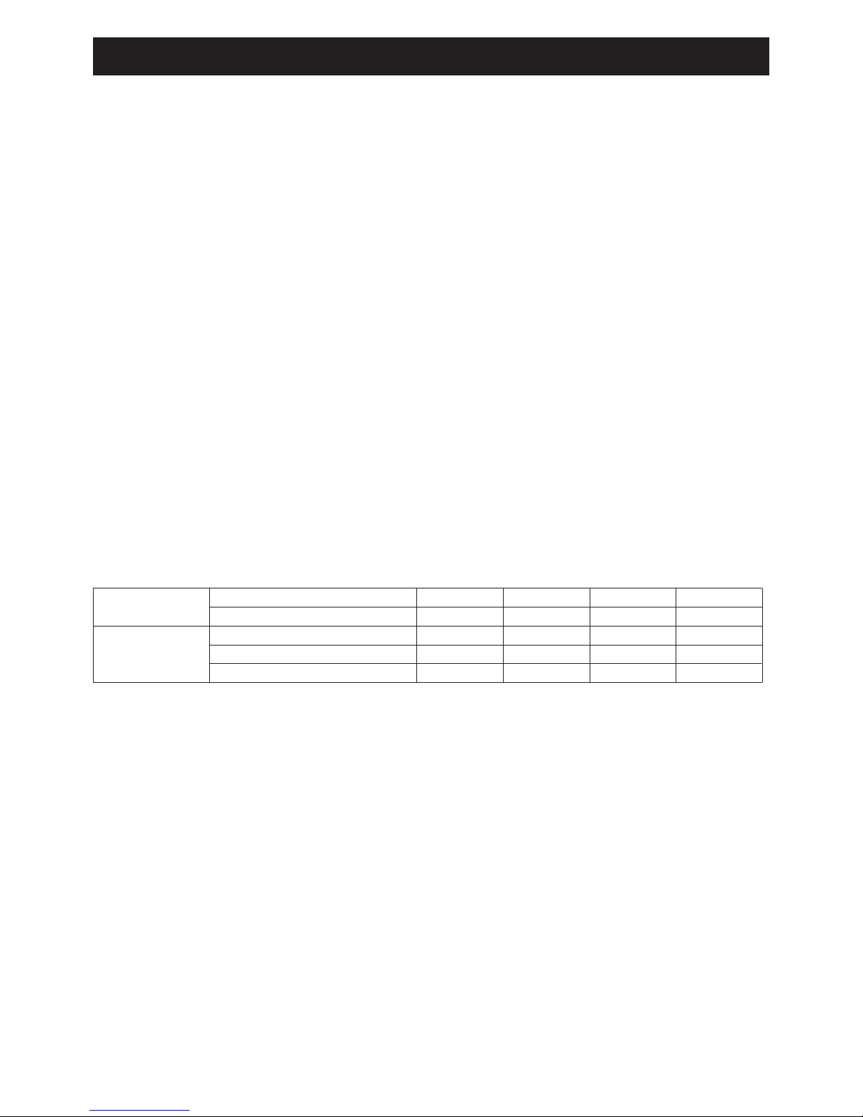
Be sure to use an exclusive power source with a circuit breaker.
Respecting the following designation, use cables whose wires size are more than the designated one in the table
below.
Power cord and circuit breaker shall be approved according to EN standard.
Supply cord must be approved in compliance with IEC60245 IEC57 (H05RN-F).
Peel ends of connecting cables in accordance with dimension in the diagram.
Use crimp-on terminals with insulating sleeves as illustrated in the diagram
below for connecting the wires to the terminal block or PCB(Terminal).
Stranded conductors shall not be soldered.
• Use a circuit breaker with a 3 mm clearance of air gap between the contacts.
Model Power supply cord(mm2)Breaker
capacity
MAX. MIN.
AEYC-0639U 2.0 1.5 16
AEYC-1039U 4.0 3.5 20
AEYC-1639U 5.5 4.0 32
This manual suits for next models
2
Table of contents
Other CHOFU Heat Pump manuals

Popular Heat Pump manuals by other brands

Envision
Envision NSKW 06 installation manual

Astral Pool
Astral Pool OPTIMA Series TECHNICAL MANUAL. START-UP AND OPERATION

ACPro
ACPro Q6SE X36 User's manual & installation instructions

alphainnoTec
alphainnoTec LWV 82R1/3 operating manual

Retro Aire
Retro Aire CM Installation, operation & maintenance manual

euroline
euroline 38VAF installation instructions


Daikin
Daikin Altherma 3 R F Installer's reference guide

Calorex
Calorex Pro-Pac Series Owners & installation manual

ACD
ACD UHD09KCH38S owner's manual

Dimplex
Dimplex LA 17PS Installation and operating instructions

Daikin
Daikin EKHBRD011ADV17 Operation manuals

Bosch
Bosch IDP Premium 18 SEER2 Series installation instructions