Unico i Series User manual


OPERATING LIMITS.............................................................................................................................................................. 1
ALLOWED MATCHUPS......................................................................................................................................................... 1
LINESET SIZES ...................................................................................................................................................................... 2
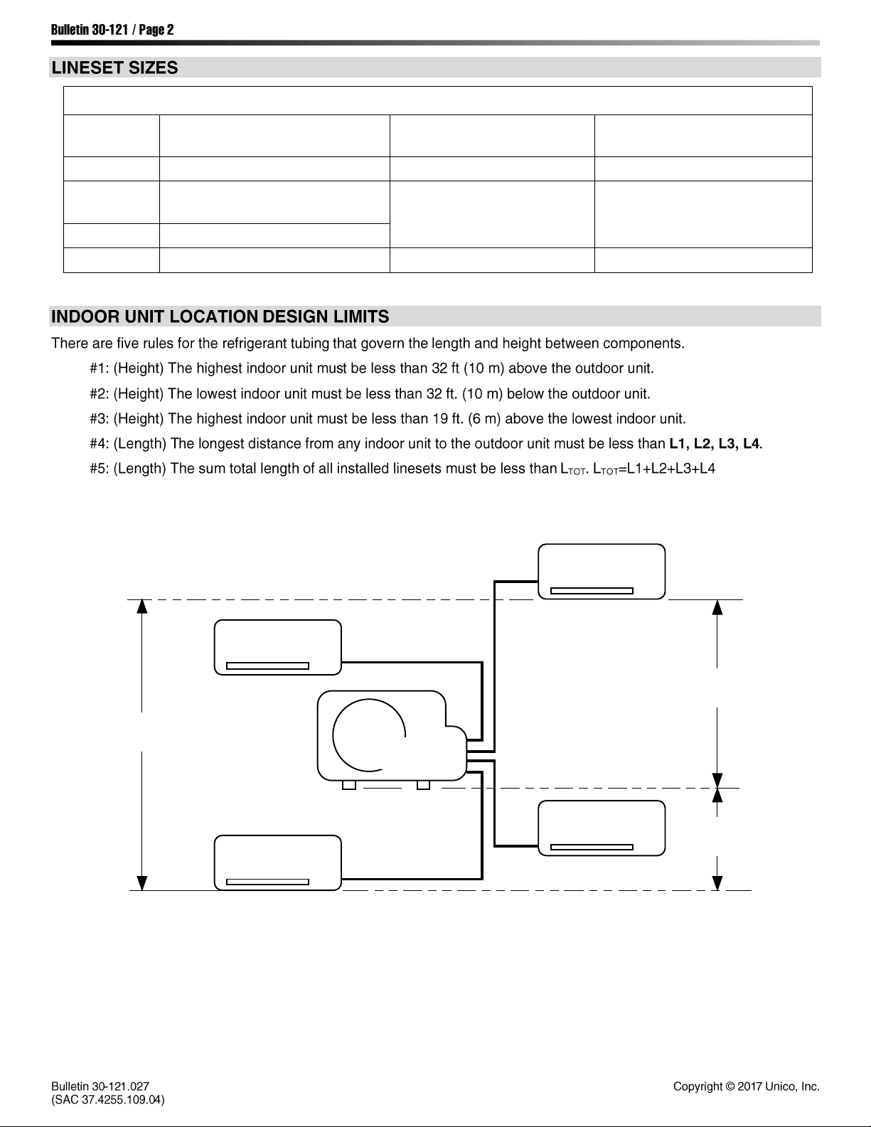
INDOOR UNIT LOCATION DESIGN LIMITS ........................................................................................................................... 2
MAXIMUM ALLOWABLE LINESET LENGTHS........................................................................................................................ 3
FACTORY REFRIGERANT CHARGE........................................................................................................................................ 3
ADDING REFRIGERANT........................................................................................................................................................ 3
OUTDOOR UNIT DIMENSIONS ............................................................................................................................................ 4
TOOLS & MATERIALS REQUIRED FOR INSTALLATION......................................................................................................... 6
POWER SUPPLY ................................................................................................................................................................... 7
OUTDOOR UNIT INSTALLATION .......................................................................................................................................... 8
PUMP DOWN PROCEDURE ............................................................................................................................................... 12
SERVICE VALVE INSTRUCTIONS......................................................................................................................................... 13
REFRIGERANT LINESET CONNECTIONS ............................................................................................................................. 14
SYSTEM WIRING DIAGRAMS ............................................................................................................................................. 22
AIR HANDLER(SDHV) INSTALLATION & CONTROL BOX WIRING....................................................................................... 26
iSERIES HEATING OPTIONS................................................................................................................................................ 29
INDOOR UNIT & REMOTE CONTROL SWITCH SETTINGS .................................................................................................. 34
SPECIAL FUNCTIONS MENU .............................................................................................................................................. 37
INDEPENDENT FAN-COIL OPERATION............................................................................................................................... 41
SDHV UNIT CIRCUIT BOARDS & WIRING DIAGRAMS........................................................................................................ 42
OUTDOOR UNIT CIRCUIT BOARDS & WIRING DIAGRAMS................................................................................................ 45
SPARE PARTS..................................................................................................................................................................... 52
TROUBLESHOOTING.......................................................................................................................................................... 60
LED CODES......................................................................................................................................................................... 61


Room Temperature
Outdoor Temperature
Minimum
Maximum
Minimum
Maximum
Cooling
Operation
50°F (10°C) D.B.
17°F (6°C) W.B.
90°F (32°C) D.B.
73°F (23°C) W.B.
-25°F (-32°C) D.B.
122°F (50°C) D.B.
Heating
Operation
41°F (5°C) D.B.
91°F (27°C) D.B.
-25°F (-32°C) D.B.
75°F (24°C) D.B.
65°F (18°C) W.B.
Full operation is guaranteed within the limits of operation. The system will ramp down outside of these limits.
Use the table at left to determine if your
system is an allowed combination. To use
the table:
1. Move vertically along the first column
to select your System Type. Single,
dual split, etc.
2. Move vertically within your System
Type to select your Outdoor Unit.
3. Use the table below to identify the size
of your Indoor Unit(s) (A, B, C, D).
4. Read horizontally through each row
within your System Type/Outdoor
Unit(ODU) pair. If the units you want
to use are contained in a single row,
then your selected system is an allowed
combination.
IMPORTANT!
Only allowed combinations may be
installed.
If a disallowed combination is installed, the
system will not operate properly!
Allowed Outdoor - Indoor Unit Combination Table
System
Type
Outdoor
Unit
Allowable Indoor Unit Size Matches
Circuit 1
Circuit 2
Circuit 3
Circuit 4
Single
Split
IS18G050
A, B
-
-
-
IS24G065
B, C
-
-
-
IS30G080
B, C
-
-
-
IS36G110
B, C, D
-
-
-
Dual
Split
IS18G050
A
A
-
-
B
A
-
-
IS24G065
-
A
A
-
B
A
-
-
B
B
-
-
IS30G080
-
A
A
-
B
A
-
-
B
B
-
-
C
A
-
-
IS36G110
-
A
A
-
B
A
-
-
B
B
-
-
C
A
-
-
C
B
-
-
Tri
Split
IS24G065
A
A
A
-
B
A
A
-
IS30G080
-
A
A
A
B
A
A
-
B
B
A
-
IS36G110
-
A
A
A
B
A
A
-
B
B
A
-
B
B
B
-
Quad
Split
IS30G080
A
A
A
A
B
A
A
A
IS36G110
A
A
A
A
B
A
A
A
B
B
A
A
B
B
B
A
Size
Indoor Unit Model Number
A
IS12MPA
B
IS24MPB
U1218L-1EA2AX
C
M2430BL1-EA2 + M2430CL1-A
D
M3036BL1-EA2 + M3036CL1-A

Table 1. Lineset Sizes, Outside Diameter
Indoor Unit
Size
Model
Small Tube (Liquid Line)
Large Tube (Vapor Line)
A
IS12MPA
1/4" (6,35 mm)
3/8" (9,52 mm)
B
IS24MPB
U1218L-1EA2AX
1/4" (6,35 mm)
1/2" (12,70 mm)
C
M2430BL1-EA2 + M2430CL-A
D
M3036BL1-EA2 + M3036CL-A
3/8" (9,52 mm)
5/8" (15,88 mm)
maximum
19 ft (6 m)
L2L2
L1
L4 L3
OUTDOOR
UNIT
INDOOR UNIT
INDOOR UNIT
INDOOR UNIT
INDOOR UNIT
IL00533a.cvx
maximum
32 ft (10 m)
maximum
32 ft (10 m)

The lengths below are the maximum lineset lengths for the given system configurations. If your installation requires a
lineset length that exceeds the pre-charged length, additional refrigerant is required. See the section Adding Refrigerant,
below, to determine how much to add.
Outdoor Unit
Model
Number of
Indoor Units
Pre-Charged (As Shipped)
With Additional Refrigerant
Maximum
combined
lineset length
(LTOT†)
Maximum
individual
lineset length
(L1, L2, L3, L4)
Maximum
combined
lineset length
(LTOT†)
Maximum
individual
lineset length
(L1, L2, L3, L4)
IS18G050
Single Split
40ft
12m
40ft
12m
80ft
25m
80ft
25m
Dual-Split
50ft
15m
40ft
12m
100ft
30m
80ft
25m
IS24G065
Single-Split
80ft
25m
80ft
25m
115ft
35m
115ft
35m
Dual-Split
100ft
30m
80ft
25m
150ft
45m
115ft
35m
Tri-Split
100ft
30m
65ft
20m
150ft
45m
100ft
30m
IS30G080
IS36G110
Single-Split
100ft
30m
100ft
30m
164ft
50m
164ft
50m
Dual-Split
130ft
40m
100ft
30m
210ft
65m
164ft
50m
Tri-Split
130ft
40m
100ft
30m
210ft
65m
100ft
30m
Quad-Split
130ft
40m
100ft
30m
210ft
65m
100ft
30m
The factory charge for each outdoor unit is listed in the table below.
Outdoor
Unit
Factory Charge
lb
kg
IS18G050
2.87
1.30
IS24G065
5.95
2.70
IS30G080
6.59
2.99
IS36G110
7.45
3.38
Lineset Size
Additional Refrigerant
Required (R410-A)
Example: An IS18G050 is installed as a single-split with a 1/4” x
3/8” line set 60 ft in length.
Solution: The outdoor unit is pre-charged for a line set length of up
to 40ft. The line length that must be compensated for is 20ft (60ft -
40ft = 20ft). Select the line set size from the table at left to find the
additional amount of refrigerant to add. You must add 0.16oz/ft.
The total amount of refrigerant that must be added is:
0.16oz/ft x 20ft = 3.2oz
No additional charge of compressor oil is necessary.
1/4" x 3/8"
0.16 oz/ft (15g/m)
1/4" x 1/2"
0.22 oz/ft (20g/m)
3/8" x 3/8"†
0.16 oz/ft (15g/m)
3/8" x 5/8"
0.49 oz/ft (45g/m)
† For eMix only.


1. Standard screwdriver
9. Hammer
16. Hex key, 5mm
2. Phillips head screwdriver
10. Drill
17. Unico P/N: A02131-K01.
Communication Tool Kit for
Troubleshooting and upgrading
firmware (requires Windows PC)
3. Knife or wire stripper
11. Tube cutter
4. Tape measure
12. Tube flaring tool
5. Level
13. Torque wrench (Yellow Jacket
#60650 or equal)
18. Refrigerant Scale
6. Sabre saw or hole saw
19. 5/16” Female x 1/4” Male SAE
Hose Adapter
7. Hacksaw
14. Adjustable Wrench
8. Drill bits 5/16" (8 mm) dia.
15. Reamer (for de-burring)
Indoor Unit Model
Item
Qty
Description
IS12MPA
1
1
Remote Control
2
2
Battery, AAA
3
1
Remote Cradle (for mounting)
4
2
Screws
M3036CL1-A
1
1
Adapter, splitter, 1/2F x 3/8F x 5/8M
2
1
Adapter, reducer, 1/4F x 3/8M with washer
Item
Qty
Description
1
1
Adapter, reducer, 3/8M x 1/2F with washer
and flare cap
2
1*
Adapter, reducer, 1/2M x 3/8F with washer
and flare cap
3
1
Cap, pipe, plastic
4
1
Connector, drain, 32mm dia w/ 18mm hose
barb
* The IS36G110 provides quantity of 2.
21
24
1 3


16"
(400)
60"
(1500)
12"
(500)
80"
(2000)
80"
(2000)
4"
(100)
12"
(500)
Dimensions in inches (mm)
4"
(100)
16"
(400)
4"
(100)
Insulation
min. 5/16" (8 mm) min. 5/16" (8 mm)

TUBE DIA.
TIGHTENING TORQUE (Approx.)
1/4" (6.4 mm)
10 - 15 lb•ft
(150 - 200 kg-cm or 14 - 20 N-m)
3/8" (9.5 mm)
25 - 30 lb•ft
(350 - 400 kg-cm or 34 - 40 N-m)
1/2" (12.7 mm)
35 - 40 lb•ft
(500 - 550 kg-cm or 47 - 55 N-m)
5/8" (15.9 mm)
45 - 60 lb•ft
(600 - 800 kg-cm or 60 - 80 N-m)
Lubricate
approx. 1/8" (3 mm) 45°

EMIX
UNIT
TO
EMIX
FRO M
EMIX
UN IT
UNIT
UNIT
UNIT

EMIX
UNIT
TO
EMIX
FRO M
EMIX
UNIT
UNIT
UN IT
UNIT

UNIT
4
UNIT
3
UNIT
2
A
B

Other manuals for i Series
1
This manual suits for next models
11
Table of contents
Other Unico Heat Pump manuals
Popular Heat Pump manuals by other brands

Tebas
Tebas INVERTER S Instruction handbook

Glen Dimplex
Glen Dimplex LA 33TPR Maintenance Instruction

STIEBEL ELTRON
STIEBEL ELTRON WWK 221 electronic Operation and installation

Mitsubishi Heavy Industries
Mitsubishi Heavy Industries HMA60-S Technical manual

York
York Sunline 2000 BCH 036 installation manual

Carrier
Carrier AQUAZONE 50PTH Installation and service instructions