chromasens allPIXA SWIR CD40199 User manual
allPIXA SWIR GigE Camera | Manual
CD40199
R01 / 2022-06-02
PMA_CHR_CD40199_R01_allPIXA_SWIR_GigE_User_Manual.docx

PMA_CHR_CD40199_R01_allPIXA_SWIR_GigE_User_Manual.docx 2
Table of Contents
allPIXA SWIR GigE Camera | Manual 1
1General information 4
1.1 About Chromasens 4
1.1.1 Contact information 4
1.1.2 Support 4
1.2 Firmware version and references 5
1.3 Definitions and abbreviations 5
1.4 Scope of supply of the allPIXA SWIR camera 7
1.5 Design of a line scan camera system 8
2Specifications and definitions 9
2.1 Camera highlights 9
2.2 Available camera models 9
2.3 Import and export regulations 10
2.4 Technical specification 10
2.5 Features Reference and SDK 11
2.6 Sensor orientation 12
2.7 Factory settings 13
3Safety 13
3.1 Depiction of safety instructions 13
3.2 Basic safety regulations 14
3.3 Safety instructions on the allPIXA SWIR camera 14
3.4 Purpose / applications 14
3.5 Staff requirements 15
3.6 Organizational measurements 15
3.7 Safety instructions for maintenance / cleaning 15
3.8 Maintenance and cleaning of the allPIXA SWIR camera 16
3.8.1 Cleaning intervals 16
3.8.2 Cleaning process 16
3.9 Disposal 16
4allPIXA SWIR –basic functionality 17
4.1 Basic design of the allPIXA SWIR camera 17
4.2 Line Scan Sensors of the allPIXA SWIR camera 18
4.2.1 Design 18
4.2.2 Spectral sensitivity 18
5Installing the allPIXA SWIR camera 19
5.1 Connectors and LEDs of the camera with GigE Vision interface 19
5.1.1 Power supply 19
5.1.2 RJ45 connector 20
5.1.3 Digital I/O connector 20
5.2 Connectors and LEDs of the camera with Camera Link interface 23
5.3 Using an encoder or external triggers 23
5.3.1 Using an encoder as line trigger source 24
5.3.2 Using an external line trigger signal 26
5.3.3 Using a light barrier to trigger frame start 27
5.4Mechanical installation 28

PMA_CHR_CD40199_R01_allPIXA_SWIR_GigE_User_Manual.docx 3
5.5 Thermal links / cooling 28
5.6 Electrical installation 29
5.6.1 Power supply 30
5.6.2 Connecting external I/O devices to the allPIXA SWIR GigE camera 30
5.6.3 Connecting the camera to the computer 31
6Working with GCT 32
6.1 Discovering and connecting the camera in GCT 32
6.2 Updating the firmware 32
7Camera system set-up 33
7.1 Installing the camera 33
7.2 Starting up the system 34
7.3 Adjusting camera and illumination 35
7.4 Creating flat field correction tables 37
8Troubleshooting and support 40
8.1 Returning material (obtain an RMA number) 40
8.2 Temperature warnings and errors 40
8.3 Before contacting Chromasens technical support 41
9Appendix 42
9.1 Support request form 42
9.2 Mechanical specification 43
9.2.1 Mechanical dimensions of the allPIXA SWIR GigE camera 43
9.3 Adapters and accessories 44
9.3.1 Power supply connector and cables 44
9.3.2 C-Mount adapter 44
9.3.3 F-Mount adapter 45
9.3.4 I/O Cables 45
9.4 EU declaration of conformity for allPIXA SIWR GigE cameras 47
9.5 EU declaration of conformity for allPIXA SIWR CameraLink cameras 48

PMA_CHR_CD40199_R01_allPIXA_SWIR_GigE_User_Manual.docx 4
1 General information
1.1 About Chromasens
The name of our company, Chromasens, is a combination of 'Chroma' which means color, and
'Sens' which stands for sensor technology.
Chromasens designs, develops, and produces high-quality and user-friendly products:
◼Line scan cameras
◼Camera systems
◼Camera illumination systems
◼Image acquisition systems
◼Image processing solutions
Today, Chromasens GmbH is experiencing steady growth and is continually penetrating new
sales markets around the globe. The company's technologies are used, for example, in products
and for applications such as book and document scanners, sorting systems and inspection
systems for quality assurance monitoring.
Customers from all over the world of a wide range of industrial sectors have placed their trust in
the experience of Chromasens in the field of industrial image processing.
1.1.1 Contact information
Chromasens GmbH
Max-Stromeyer-Str. 116
78467 Konstanz
Germany
Phone: +49 (0) 7531 / 876-500
Fax: +49 (0) 7531 / 876-303
Email: support@chromasens.de
HP: https://www.chromasens.de/
1.1.2 Support
Should you ever have problems with the allPIXA SWIR camera that you cannot solve by
yourself, look into this manual for additional information, check the troubleshooting chapter 10,
contact your local distributor, or send us an e-mail.
Chromasens GmbH
Max-Stromeyer-Str. 116
78467 Konstanz
Germany
Phone: +49 (0) 7531 / 876-500
Fax: +49 (0) 7531 / 876-303
Email: support@chromasens.de
HP: https://chromasens.de/support
Visit our website at https://www.chromasens.de which features detailed information on our
company and products.

PMA_CHR_CD40199_R01_allPIXA_SWIR_GigE_User_Manual.docx 5
1.2 Firmware version and references
This document refers to the following firmware and document versions:
◼allPIXA SWIR GigE Camera Firmware Package Version 1.3.0
◼Features Reference for allPIXA SWIR Camera XML Version 4.5.3
◼GenICam Standard Features Naming Convention (SFNC) Version 2.7
Newer firmware versions may contain additional features and bugfixes. Check
https://chromasens.de/allpixa-swir-downloads or contact the Chromasens support for updates.
1.3 Definitions and abbreviations
Term /
Abbreviation
Synonym /
Meaning
Expanation
Black level
Offset
Used for additive (“brightness”) corrections, see
also gamma
Camera Link®
Communication
protocol standard
for camera interface
applications
The Camera Link standard is maintained and
administered by the Automated Imaging
Association (AIA), , now part of the Association for
Advancing Automation (A3)
Corona II
LED illumination
Chromasens product
DHCP
Dynamic Host
Configuration
Protocol
A network management protocol for automatically
assigning IP addresses. See DHCP (Wikipedia)
DSNU
Dark signal non-
uniformity
Irregularity in the dark image (offset of the
individual pixels), additive part of the fixed-pattern
noise (FPN)
DVAL
Data valid
Pixel-by-pixel enabled for Camera Link
FFC
Flat-field correction
Can be used to correct the fixed-pattern noise of
the image sensor, the vignetting of the lens, and
the non-uniformity of the illumination. FFC is
performed in the camera by means of dark signal
non-uniformity (DSNU) and photo response non-
uniformity (PRNU) correction tables
FPN
Fixed-pattern noise
Temporally constant lateral non-uniformity of the
imaging system
FVAL
Frame valid
Frame signal for an image on the Camera Link
(corresponds to VSync)
Gain
Used for multiplicative (“contrast”) corrections
Gamma
Gain, BlackLevel and Gamma features will
transform the original pixel value Y to a new value
Y' according to the following formula:
GCT
GenICam Control
Tool
Chromasens camera control and configuration tool
for GenICam cameras
GenICam™
Generic Interface
for Cameras
Generic camera programming interface standard
published and maintained by the European
Machine Vision Association emva.org
GigE Vision®
Ethernet-based
Camera interface
standard
Camera interface standard using the Gigabit
Ethernet communication protocol initiated by the
Automated Imaging Association (AIA), now part of
the Association for Advancing Automation (A3)
GPIO
General-purpose
input/output
Versatile, configurable digital signal pin, e.g. at the
digital I/O connector of the camera (see section
5.1.3)
LED
Light emitting diode
-

PMA_CHR_CD40199_R01_allPIXA_SWIR_GigE_User_Manual.docx 6
Term /
Abbreviation
Synonym /
Meaning
Expanation
LLA
Link-local address
Local IP address, typically automatically assigned
when no DHCP server is available.
See LLA (Wikipedia) and Zero-
configuration_networking (Wikipedia)
LUT
Lookup table
Array with precalculated values, to store e.g.,
gamma correction or tone response curves (TRCs)
LVAL
Line valid
Frame signal for a line on the Camera Link
LVTTL
Low-voltage TTL
Transistor-Transistor-Logic with reduced supply
voltage (3.3 instead of 5V). See e.g. Transistor–
transistor_logic Sub-types (Wikipedia)
PRNU
Photo response
non-uniformity
Difference in sensitivity of the individual pixels,
multiplicative part of the fixed-pattern noise (FPN)
ROI
Region of interest
A rectangular section of the captured frame or a
contiguous subsection of the image sensor. Can
already be defined in the camera, e.g., to reduce
the amount of data to be transferred or to increase
the achievable frame rate.
RS422
RS-422,
TIA/EIA-422
Technical standard for Differential Interface
Circuits. See e.g. RS-422 (Wikipedia)
SDK
Software
Development Kit
A set of tools, headers, libraries, sample code, and
documentation to facilitate software developers
creating custom applications.
SFNC
GenICam Standard
Features Naming
Convention
Provides a standard features naming convention
and a standard behavioral model for the devices
based on the GenICam standard. Can be
downloaded free of charge on the GenICam
download page of the emva.org web site.
TRC
Tone reproduction
curve (or tone
response curve)
Can be used to encode more complex response
curves (like the L* or sRGB response curve) as
LUTs which can otherwise only be approximated by
a gamma value.
VSync
Vertical
synchronization
Frame signal for an image (corresponds to FVAL)
White
reference
The white reference is a physical patch in the field
of view of the camera that can be used for gain
adjustment
XLC4
Light controller
Controller that permits to control up to four
channels of Corona II illuminations.

PMA_CHR_CD40199_R01_allPIXA_SWIR_GigE_User_Manual.docx 7
1.4 Scope of supply of the allPIXA SWIR camera
Check your device upon delivery to ensure that it is undamaged and complete.
The following components are supplied with the allPIXA SWIR camera:
◼allPIXA SWIR camera packaging
Check the packaging for damage, which may have occurred during transport.
◼allPIXA SWIR camera with C-mount adapter
Check the camera for damage, which may have occurred during transport.
The rating plate is located on the rear of the allPIXA SWIR camera. It shows the camera
resolution and the serial number.
◼Additionally ordered and supplied accessories
Cables, extension rings, lenses and other accessories are not included in the standard scope
of delivery. These items must be ordered separately as accessories.
Check additionally ordered accessories for completeness and for damage, which may have
occurred during transport.
Read this manual carefully before using the camera, contacting your local partners or the
Chromasens support.
Should there be any questions left, do not hesitate to contact your local partner or us.
We would be pleased to be of assistance to you.
PMA_CHR_CD40199_R01_allPIXA_SWIR_GigE_User_Manual.docx 8
1.5 Design of a line scan camera system
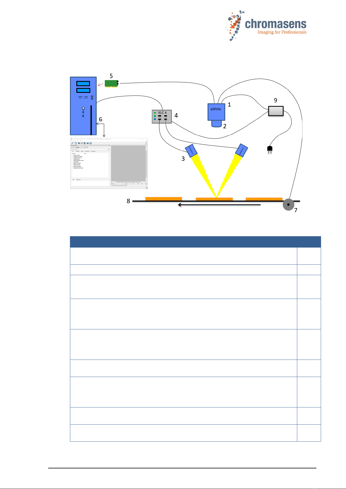
The following figure demonstrates the basic setup of a typical line scan camera system:
Figure 1: Design of a line scan camera application
The following components are present in typical line scan camera applications:
Component
No.
Line scan camera: An allPIXA SWIR camera, which scans the image line by line and
communicates with the PC (5).
1
The optical system: Optical lenses with tubes and mounts with an adjusted focusing
2
Illumination: The illumination system lights up the information carrier / scan area on
the passing object. The Chromasens Corona II SWIR illumination system is an ideal
supplementary option for the allPIXA SWIR camera.
3
Illumination controller: Controls and monitors the illumination unit. The Chromasens
Corona II illumination (3) has integrated temperature sensors which can be read out
with the XLC4 controller. By use of the XLC4 controller, the illumination unit can be
monitored and kept stable.
4
Network cable and suitable network adapter: The image data are sent to a PC
using a standard 1000BASE-T network connection. Use a Cat-5e, Cat-6, or better
S/STP Gigabit Ethernet cable and a suitable Gigabit Ethernet network adapter in the
PC.
5
PC: The PC system performs subsequent processing of the image data and can
optionally control the illumination system (3 + 4).
6
Speed control: The line rate of the camera can be controlled and synchronized with
the transport speed of the object or conveyor belt by means of an optional rotary
encoder or external line trigger signal. Synchronization of the camera with strobed
illumination is also possible this way.
7
Conveyor unit: The conveyor unit moves the scanned object past the allPIXA SWIR
camera.
8
Power supply: Both, the allPIXA SWIR camera and the illumination system, require a
suitable power supply.
9
PMA_CHR_CD40199_R01_allPIXA_SWIR_GigE_User_Manual.docx 9
2 Specifications and definitions
The allPIXA SWIR GigE camera is compliant with the GigE Vision 2.0 specification which
defines the communication interface protocol for any GigE Vision device. The device description
of the camera is contained in an XML file. For more information about GigE Vision see:
https://www.automate.org/a3-content/vision-standards-gige-vision.
Flat-field correction (FFC), which consists of an offset and a shading correction, compensates
for differences in pixel sensitivities, lens vignetting, and lighting unevenness.
FFC is performed in the camera by means of dark signal non-uniformity (DSNU) and photo
response non-uniformity (PRNU) correction tables.
DSNU and PRNU correction tables can be created with the in-camera wizard, saved to the PC,
and later restored to the camera.
By default, the camera is delivered with a C-Mount adapter. An F-Mount is available as
accessory. Other lens adapters are available on request.
2.1 Camera highlights
The allPIXA SWIR camera is especially suitable for inspection systems requiring a very high
speed and a consistently high image quality.
◼Short-wave infrared line scan camera
◼High-speed InGaAs line scan sensor with 512 or 1024 pixels and up 40 kHz line frequency
◼8, 10 or 12-bit mono output
◼Digital I/O port on GigE camera models for direct input and output of external trigger signals,
e.g. from/to incremental encoders, photoelectric sensors or lighting controllers
◼Built-in floating point encoder frequency converter to simplify synchronization between camera
and transport speed
◼Flatfield correction: Factory calibration and internal wizard for calculating custom shading
(PRNU) and offset (DSNU) corrections
◼Robust metal housing
◼Lens adapter: C-Mount lens adapter included, F-Mount adapter available as accessory
◼Internal test image generator
2.2 Available camera models
The allPIXA SWIR camera is available in the following configurations:
GigE version
CP000700-IR-01K-GE
CP000700-IR-512-GE
Camera Link version
CP000700-IR-01K-CL
CP000700-IR-512-CL
Number of pixels
1024
512
pixels
Pixel size
12.5 x 12.5
25 x 25
µm
Image size
12.8 x 0.0125
12.8 x 0.025
mm
Spectral response range
950 … 1700
nm

PMA_CHR_CD40199_R01_allPIXA_SWIR_GigE_User_Manual.docx 10
2.3 Import and export regulations
IMPORTANT
NOTE:
We would like to point out that the cameras described in this manual are
covered by Annex I to EC Regulation No. 2021/821 under ECCN 6A003,
also known as "dual-use” items. Prior the import, export, transit or
transfer, the exporter shall diligently check on its own responsibility for
any applicable reporting or license requirements, restrictions, and
prohibitions. The import, export, transit, or transfer may be subject to
licensing requirements, or prohibited in accordance with the
aforementioned regulation. We also point out that similar licensing
obligations as well as restrictions or prohibitions may apply outside the
European Union according to the respective export control law and
regulations of the country from where the products shall be exported to or
shall be imported into.
2.4 Technical specification
Sensor
InGaAs short-wave infrared line sensor
Spectral sensitivity
950 nm to 1700 nm
Resolution
1024 px or 512 px
Pixel size
12,5 µm or 25 µm (square)
Pixel bit depth
8 / 10 / 12 bit
Line scan operating mode
Free-running / software trigger /
external trigger
Maximum line frequency
40 kHz
Minimum integration time
21 µs
Interface
GigE Vision (1000BASE-T, RJ-45)
Other interfaces
Power supply (6-pin Hirose, male)
External I/O (12-pin Hirose, male)
Digital input
3x RS422 or LVTTL
Digital output
2x RS422
Lens mount
C-Mount (F-Mount on request)
Protection class
IP40
Conformity
CE, RoHS
Power supply
12 to 24 VDC +/- 10 %; 6 W
Housing dimensions
L = 62 mm, H = 62 mm, D = 52 mm
Weight
170g
Storage temperature
-20 °C to +70 °C; -4 °F to +158 °F
Operating temperature (housing)
-10 °C to +50 °C; +14 °F to +122 °F
Maximum operating temperature mainboard
+100 °C; +212 °C
Maximum operating temperature sensor
+60 °C; +140 °F
Air humidity during operation
10% - 90% relative air humidity,
non-condensing

PMA_CHR_CD40199_R01_allPIXA_SWIR_GigE_User_Manual.docx 11
General ambient conditions
Operation
IEC 721-3-3:IE33
Transport
IEC 721-3-2:IE21
Storage
IEC 721-3-1:IE11
NOTE:
You should use thermal conductive mounting (for example direct attachment
on metal frame) to decrease temperature, improve camera performance and
avoid damages to the camera. See also section 5.5.
2.5 Features Reference and SDK
For detailed information on camera controls and features, please refer to the allPIXA SWIR
Features Reference, which is available on the allPIXA SWIR download page
https://chromasens.de/allpixa-swir-downloads and to the GenICam Standard Features Naming
Convention (SFNC) which is available free of charge on the GenICam download page of the
EMVA web site https://www.emva.org/.
The allPIXA SWIR Features Reference describes all standard and camera specific GenICam
features. Make sure that you always refer to the features reference that matches the XML
version used in your firmware.
Further documentation and downloads for software developers can be found in the Chromasens
Download Center https://chromasens.de/downloads. The Windows SDK is optional component
of the GCT installer, the Linux SDK is available on request.
PMA_CHR_CD40199_R01_allPIXA_SWIR_GigE_User_Manual.docx 12
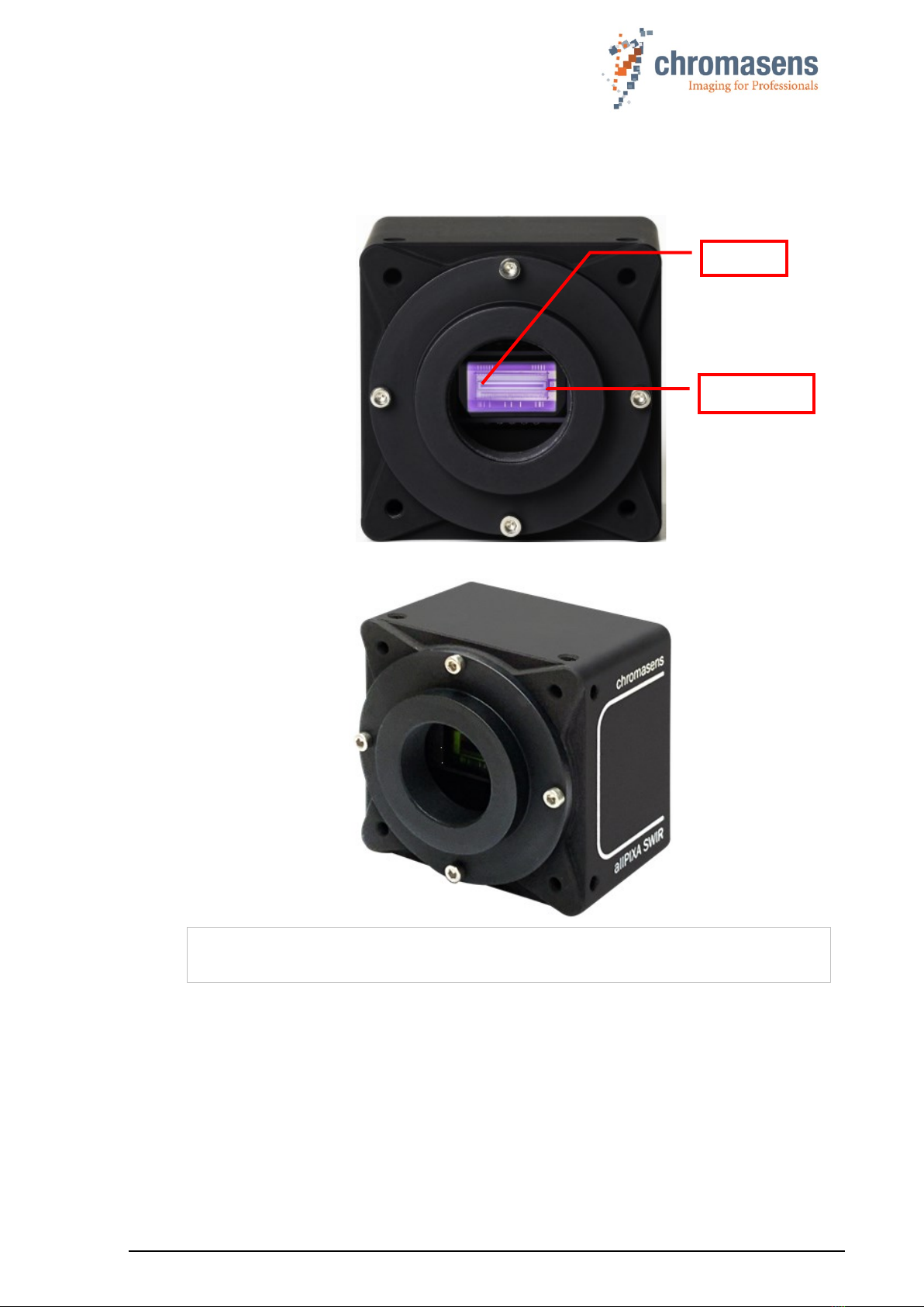
2.6 Sensor orientation
The sensor lines of different camera models vary in length, depending on maximum resolution
and pixel size.
Figure 2: Camera sensor line location
NOTE
The logo Chromasens on the side of the camera indicates the orientation of the
pixel line and the position of the first pixel.
Pixel 1
Sensor line

PMA_CHR_CD40199_R01_allPIXA_SWIR_GigE_User_Manual.docx 13
2.7 Factory settings
SWIR cameras are delivered with the following factory settings, which can be changed in the
Gev Interface Selector 0 of the GigE Vision subcategory in the Transport Layer Control
feature group:
Gev Feature
Value
Persistent IP Address
192.168.100.10
Persistent Default Gateway
0.0.0.0
Persistent Subnet Mask
255.255.255.0
Current IP Configuration LLA
On
Current IP Configuration DHCP
On
Current IP Configuration Persistent IP
Off
To use DHCP or LLA autoconfiguration, you have to disable Persistent IP as this has the
highest priority.
3 Safety
3.1 Depiction of safety instructions
Safety-relevant information is indicated in this manual as follows:
WARNING
Indicates a potentially hazardous situation or task, which, if not avoided,
could result in serious injury or death.
CAUTION
Indicates a potentially hazardous situation or task, which, if not avoided,
may result in minor or moderate injury.
Indicates a potentially hazardous situation or task, which, if not avoided, could
result in damage to the product or the surrounding environment.

PMA_CHR_CD40199_R01_allPIXA_SWIR_GigE_User_Manual.docx 14
3.2 Basic safety regulations
Always observe the following:
◼Do not attempt to install the device or start operation before you have read all supplied
documentation carefully and have understood its contents.
◼Safe and correct operation of the device requires correct and appropriate transport, storage,
mounting and installation as well as careful operation and maintenance.
◼Operation of the allPIXA SWIR camera device is only permitted if it is in a faultless and safe
condition. If a fault or defect occurs, the allPIXA SWIR camera, the machine, or the system in
which the allPIXA SWIR camera is installed, must be stopped immediately, and the responsible
person must be informed.
◼Modifications and extensions to the allPIXA SWIR camera are only permitted if the prior written
consent of Chromasens GmbH is obtained. This applies in particular to modifications and
extensions which can negatively affect the safety of the allPIXA SWIR camera.
◼Compliance with the ambient conditions described in this manual is essential.
3.3 Safety instructions on the allPIXA SWIR camera
Risks from hot surfaces
The body of the allPIXA SWIR camera heats up during operation.
Do not touch hot surfaces without suitable protective gloves. Always allow hot
surfaces to cool down before carrying out any work on the unit.
Electric voltage hazard
The allPIXA SWIR camera runs with electric power. Before any work is carried
out on the allPIXA SWIR camera, be aware to disconnect the mains cables.
Make sure that the device is safely isolated from the power supply!
Risk of electrostatic discharge
The allPIXA SWIR camera contains components and units which are sensitive
to electrostatic charge.
Observe all precautionary measures for handling electrostatically sensitive
equipment.
Make sure that the allPIXA SWIR camera, its corresponding tools, its equipment,
and the person who is handling it have the same electrical potential.
3.4 Purpose / applications
◼The allPIXA SWIR camera is designed for machines and systems which are used for
commercial and industrial applications.
◼The owner of the machine or system in which the allPIXA SWIR camera has been installed is
responsible for compliance with relevant safety regulations, standards, and directives.
Commissioning of the allPIXA SWIR camera is only permitted if the machine or system, in which
the allPIXA SWIR camera is installed, complies with the safety regulations and standards of the
country in which the allPIXA SWIR camera runs.
◼The owner of the machine or system with the installed allPIXA SWIR camera must verify the
suitability of allPIXA SWIR camera for its intended use.
◼Safety regulations of the country in which the device is used must be complied with it.
◼The allPIXA SWIR camera may only be connected or used as described in this manual.

PMA_CHR_CD40199_R01_allPIXA_SWIR_GigE_User_Manual.docx 15
◼The allPIXA SWIR camera must be set up and installed in compliance with the instructions
contained in this manual.
3.5 Staff requirements
◼The system owner must ensure that all persons working on the system are trained for the
required work and have read and understood this manual. This applies particularly to the
employees who only work occasionally with the allPIXA SWIR camera, for example, during
commissioning and maintenance work.
◼Work on the electrical installation of the system may only be carried out by a qualified electrician
or persons who have undergone the necessary electrotechnical training under the supervision
of a qualified electrician, in compliance with applicable electrotechnical regulations.
◼Be aware that only suitably trained and qualified persons are permitted to work with the allPIXA
SWIR camera. Such persons are qualified to work with the allPIXA SWIR camera device if they
are familiar with its assembly, installation, care, and all necessary precautionary measures.
◼Assignments and responsibilities of the staff charged with operation, commissioning,
maintenance, and repair must be clearly defined and specified by the owner of the device in
which the allPIXA SWIR camera is installed.
3.6 Organizational measurements
◼The instruction manual must be stored safely in the vicinity of the camera in operation.
◼Information contained in this manual must be integrated into the documentation of the device in
which the allPIXA SWIR camera is installed.
◼The allPIXA SWIR camera and all connected peripheries must be checked regularly for visible
external damages.
3.7 Safety instructions for maintenance / cleaning
◼Before any service or maintenance work is carried out, the responsible staff must be informed.
◼Deadlines and intervals for regular inspections must be complied with.
◼Before maintenance is started, the allPIXA SWIR camera must be isolated from the power
supply.
◼Due to the risk of fire, devices such as radiators, heaters, or lighting equipment must be allowed
first to cool down.
◼Only technicians of the Chromasens GmbH are permitted to open or slacken screws or housing
sections of the allPIXA SWIR camera.
◼Necessary repairs may only be carried out by Chromasens GmbH.
◼Cleaning of the device is only allowed with a soft, lint-free cloth and Isopropanol (optional).
◼To avoid damages, the camera should only be transported in its original packaging.
PMA_CHR_CD40199_R01_allPIXA_SWIR_GigE_User_Manual.docx 16
3.8 Maintenance and cleaning of the allPIXA SWIR camera
During operation of the device, particles such as dust etc. may be settled on the optical
components (lens) of the camera. These deposits affect the optical image and the function of
the camera negatively.
Chromasens recommends regular inspection and cleaning. The cleaning
intervals depend on the actual operating and ambient conditions (for example
dust-laden atmosphere).
3.8.1 Cleaning intervals
Cleaning intervals depend on the environment. Regular inspection and cleaning intervals must
be specified depending on the degree of soiling.
3.8.2 Cleaning process
Body of the allPIXA SWIR camera heats up during operation.
Before cleaning, you must switch off the device. Always allow hot surfaces
to cool down before cleaning the device.
The device works with electric power. Before cleaning the device, make
sure that the device is disconnected from the power supply.
All surfaces requiring cleaning can be wiped with a soft, lint-free cloth which can be moistened
with Isopropanol.
Never use any other liquid or cleaning agent than those stated in this manual.
Never use hard or sharp tools for cleaning the device.
Inspect the device to ensure that cleaning was effective and repeat, if necessary.
If it is not possible to clean a component due to irremovable contamination, it must be replaced.
3.9 Disposal
This symbol indicates that electrical and electronic equipment should not be
disposed with normal garbage at the end of its working life. To prevent
possible harm to the environment or human health from uncontrolled waste
disposal, please separate this from other types of wastes and recycle it
responsibly to promote the sustainable reuse of material resources.
Please dispose this product in accordance with your local regulations and contact your local
government office, for details of where and how they can take this item for environmentally safe
recycling.
PMA_CHR_CD40199_R01_allPIXA_SWIR_GigE_User_Manual.docx 17
4 allPIXA SWIR – basic functionality
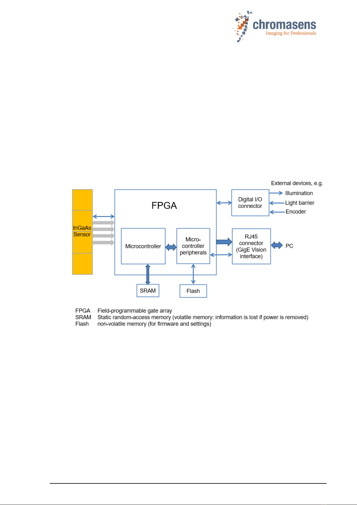
4.1 Basic design of the allPIXA SWIR camera
During operation, an object is scanned line by line by the InGaAs sensor.
The FPGA also includes a softcore microcontroller (or microprocessor) with its peripherals like
RAM and flash memory. The software running in the microcontroller configures and supports
the FPGA logic to process and transfer image data and to communicate with the host
application.
The allPIXA SWIR camera can be used and configured with any GigE Vision 2.0 compliant
Software or SDK. We recommend using the Chromasens GenICam Control Tool (GCT) and the
Chromasens SDK which is available for Linux and Windows. The Windows SDK is an optional
component of the GCT installer, the Linux SDK is available on request.
External trigger signals from sources like incremental encoders, light barriers, or light and trigger
controllers can be input by the GPIOs (general purpose inputs/outputs) of the Digital I/O
connector of the GigE models or by the CC of the camera.
Figure 3: Basic design of the allPIXA SWIR camera (block diagram)
PMA_CHR_CD40199_R01_allPIXA_SWIR_GigE_User_Manual.docx 18
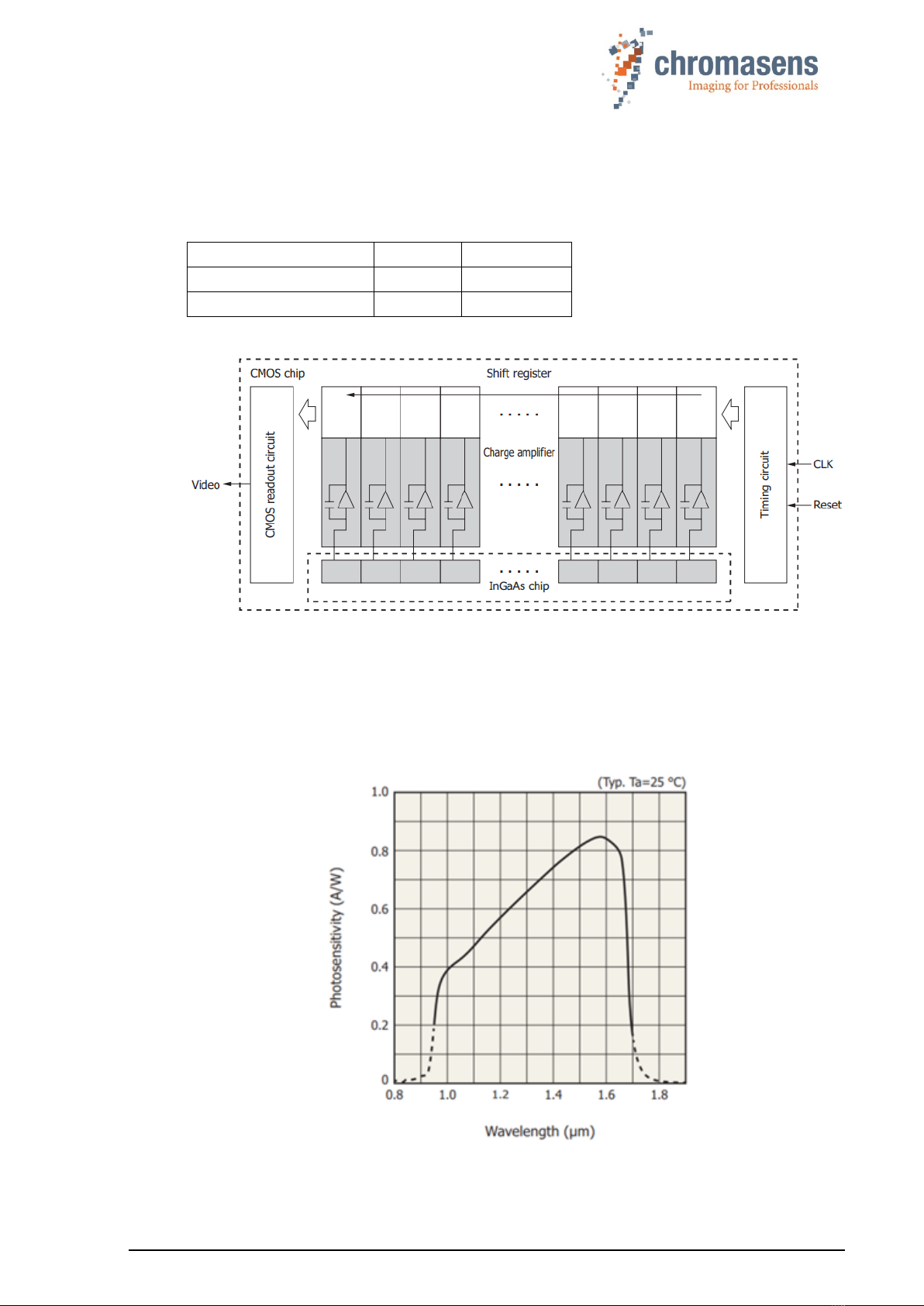
4.2 Line Scan Sensors of the allPIXA SWIR camera
4.2.1 Design
The allPIXA SWIR camera is available with two sensor variants:
Total number of pixels
512
1024
Pixel size (µm)
25 x 25
12.5 x 12.5
Pixel pitch (µm)
25
12.5
Figure 4: Camera sensor (block diagram)
4.2.2 Spectral sensitivity
The figure below represents the spectral response of the camera sensor (spectral responsivity
in A/W). The representation is based on sensor vendor information.
Normalized spectral sensitivity of the color camera (range 950nm –1700nm):
Figure 5: Spectral sensitivity of the line scan sensor
PMA_CHR_CD40199_R01_allPIXA_SWIR_GigE_User_Manual.docx 19
5 Installing the allPIXA SWIR camera
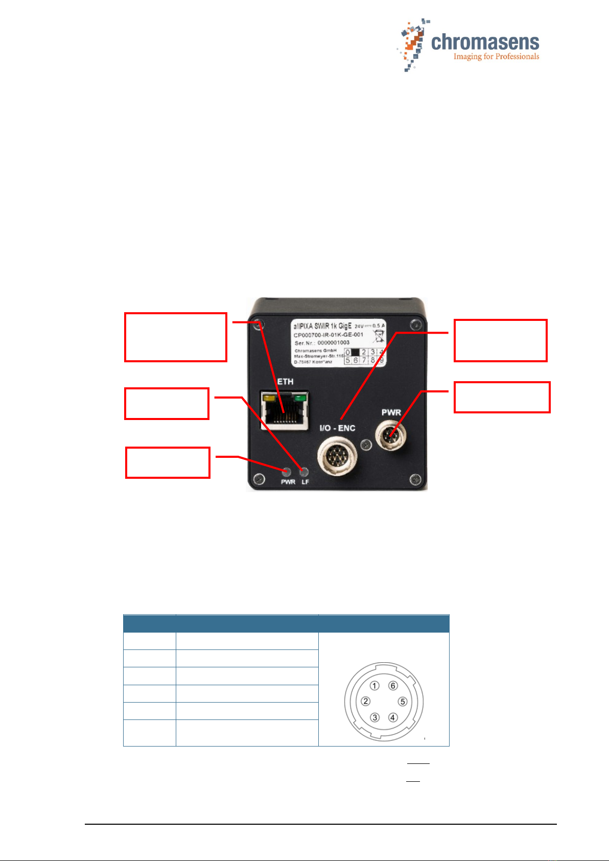
5.1 Connectors and LEDs of the camera with GigE Vision interface
On the backside of the camera, you find the following interfaces:
◼An RJ-45 Gigabit Ethernet connector for image signaling and for communication between the
allPIXA SWIR camera and the image processing computer.
◼A general-purpose digital input/output (GPIO) connector (Hirose 12 pin HD10A-10P-12S(73)
male) to connect external trigger sources like incremental encoders, light barriers or other
external devices.
◼A power connection (Hirose HR10A-7P-6S(73) male) for power supply
◼A red power LED, which indicates whether the allPIXA SWIR camera is connected to the
power supply.
◼An orange status LED, which blinks as soon as the camera firmware has booted successfully.
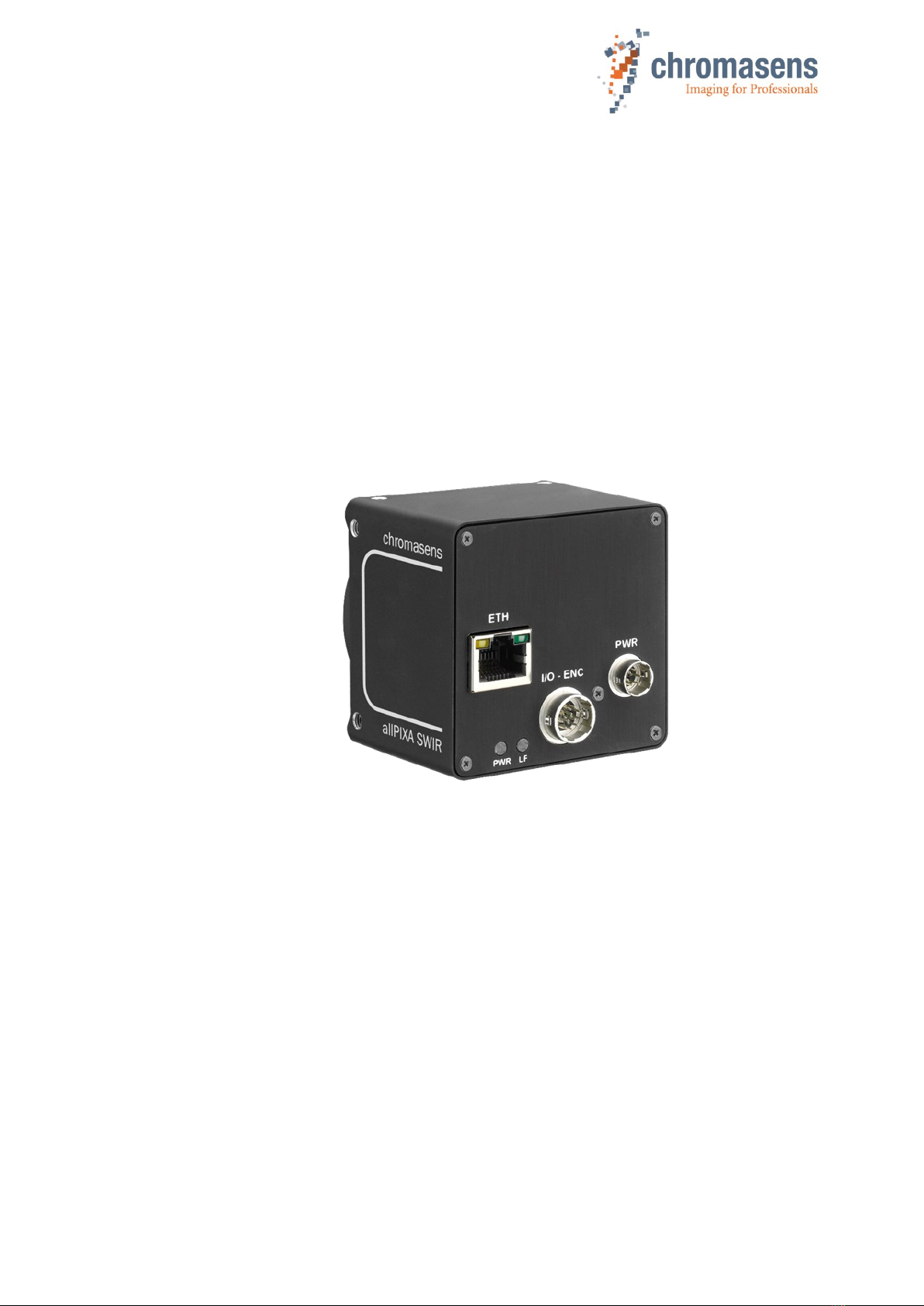
Figure 6: Connections and LEDs of the allPIXA SWIR GigE camera
5.1.1Power supply
Following connector is required for the power supply cable:
Manufacturer: Hirose
Manufacturer Part no.: HR10A-7P-6S “female”
(male counterpart is located on the camera)
Pin no.
Description
1
Power +24 V
Connector on camera
(male, front view):
2
Power +24 V
3
Not connected
4
Ground
5
Ground
6
Not connected
For available power supply cables and connectors see section 9.3.1.
For more details about input voltage and currents, see section 2.4.
RJ-45 Gigabit
Ethernet jack
(GigE Vision)
Power LED
Status LED
Digital I/O
connector
Power connector
PMA_CHR_CD40199_R01_allPIXA_SWIR_GigE_User_Manual.docx 20
5.1.2 RJ45 connector
The GigE RJ-45 jack connector permits to use a Cat-5e, Cat-6 or better S/STP Gigabit Ethernet
cable with lengths of up to 100 m.
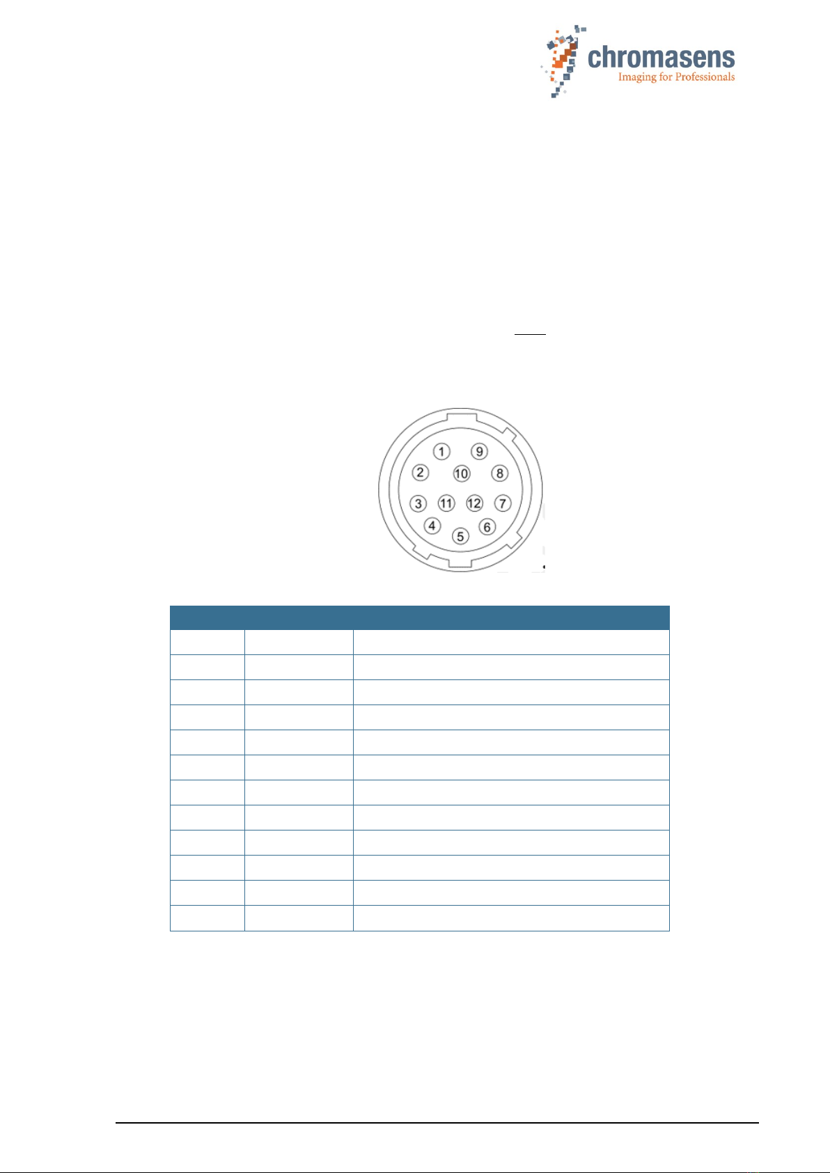
5.1.3 Digital I/O connector
Manufacturer and Type: Hirose 12 pin (male part on camera side)
Standard mating part: HR10A-10P-12S(73) (female on cable).
Mating cables: T18445 (5m, straight, open leads),
T18446 (5m right angle, open leads).
For more details about available I/O cables, see section 9.3.4.
You can connect up to three digital input signals and two digital output signals to the digital I/O
connector of the camera.
Figure 7: I/O connector on camera (male, front view)
Pin
Signal
Description
1
IN1 -
RS422 Digital Input Line 1 -
2
IN1 +
RS422 or LVTTL Digital Input Line 1 +
3
IN3 -
RS422 Digital Input Line 3 -
4
IN3 +
RS422 or LVTTL Digital Input Line 3 +
5
GND I/O
I/O Ground reference
6
OUT1 -
RS422 Digital Output Line A -
7
OUT1 +
RS422 Digital Output Line A +
8
IN2 -
RS422 Digital Input Line 2 -
9
IN2 +
RS422 or LVTTL Digital Input Line 2 +
10
N.C.
Not Connected
11
OUT2 -
RS422 Digital Output Line B -
12
OUT2 +
RS422 Digital Output Line B +
Table of contents
Other chromasens Digital Camera manuals


