chromasens allPIXA User manual

allPIXA wave camera | Manual
CD40172 Version 1.0

Chromasens allPIXA wave - CD40172 Version 1.0 2
Table of Contents
1General information 8
1.1 About Chromasens 8
1.1.1 Contact information 8
1.1.2Support 8
1.2 Firmware and software version in this manual 9
1.3 List of abbreviations 9
1.4 Definitions 10
1.5 Scope of supply of the allPIXA wave camera 11
1.6 Information about the Camera Setup Tool (CST) 11
1.7 Design of a line scan camera system 12
2Specifications and definitions 13
2.1 Camera highlights 14
2.2 Camera speed for available Camera Link modes and frequency 14
2.3 Technical specification 15
2.4 Mechanical specification 16
2.4.1 Mechanical dimensions of the allPIXA wave 10k camera 16
2.4.2 Mechanical dimensions of the allPIXA wave 15k camera 17
2.5 Sensor alignment and orientation 18
2.6 Adapter and accessories 19
2.6.1 Lenses adapters and mounts 19
2.6.2 Accessories for the allPIXA pro 2k & 4k camera S-Series 20
2.6.3 Accessories for the allPIXA pro 6.000px and 7.3k camera W-Series 21
2.6.4 Mounting of the extension tube systems 22
2.6.5 Mounting of a lens adapter ring 22
2.6.6 Environmental requirements 23
3Safety 24
3.1 Depiction of safety instructions 24
3.2 Basic safety regulations 24
3.3 Safety instructions on the allPIXA wave camera 25
3.4 Purpose / applications 25
3.5 Staff requirements 26
3.6 Organizational measurements 26
3.7 Safety instructions for maintenance / cleaning 26
3.8 Maintenance and cleaning of the allPIXA wave camera 27
3.8.1 Cleaning intervals 27
3.8.2 Cleaning process 27
3.9 Disposal 27
4allPIXA wave –basic functionality 28
4.1 Basic design of the allPIXA wave camera 28
4.2 Design of the allPIXA wave camera line scan sensor 29
4.3 The allPIXA wave camera line scan sensor pixel arrangement 29
4.4 Image processing 30

Chromasens allPIXA wave - CD40172 Version 1.0 3
4.4.1 Digital image processing 30
4.4.2 Supported Camera Link modes 31
4.5 Black-level correction and shading (flat-field) correction 31
4.6 Feature: Image mode (frame scan mode) 33
4.7 Monochrome image acquisition 33
4.8 White balancing with a closed-loop control 33
4.9 Setting concept 34
4.10 Restore factory default 34
4.11 Chromasens API - communication 35
5Installing the allPIXA wave camera 36
5.1 Interface and status LED 36
5.1.1 Power supply 37
5.1.2 Config UART (serial RS 232, RS485) 37
5.1.3 Digital IO port 38
5.1.4 LVCMOS and RS422 levels 39
5.1.5 Video Camera Link port 1 and 2 39
5.1.6 Status LED 39
5.2 Mechanical installation 40
5.3 Thermal links / cooling 40
5.4 Preventing installation errors 41
5.4.1 Conveyor belt tracking 41
5.4.2 Perpendicularity of the sensor to the direction of transport 41
5.4.3 Rotation around the longitudinal axis of the line scan sensor 42
5.4.4 Rotation around the transverse axis of the line sensor 43
5.5 Electrical installation 44
5.6 Connecting the camera to the PC 45
5.7 Update the firmware of the allPIXA wave camera 46
6Configuring the camera using the Camera Setup Tool 51
6.1 Installing the Camera Setup Tool (CST) 51
6.1.1 System Requirements 51
6.1.2 Installation of the CST Software 51
6.1.3 Establishing communication between camera and PC 53
6.2 CST program window 55
6.3 Toolbar 56
6.4 CST menu bar 57
6.5 Simple Setup View (overview) 60
6.6 Basic camera parameter settings (overview) 61
6.6.1 Camera parameter 61
6.6.2 Image parameter 64
6.6.3 Special functions (Test pattern / Tracing / Register edit) 66
6.6.4 General information 67
6.6.5 Controlling LED lighting 67
6.7 Opening serial connection to a camera 68
6.8 Transferring data to the camera 68
6.9 Saving data to the camera permanently 69
6.10 Refreshing data from the camera in CST 69

Chromasens allPIXA wave - CD40172 Version 1.0 4
6.11 Selecting a setting on the camera 70
6.12 Saving settings to the PC 70
6.12.1 Saving settings from CST to hard disk 70
6.12.2 Saving settings from the camera to hard disk 70
6.13 Transferring saved settings from the PC to the camera 71
6.14 Deleting settings on the camera 72
6.15 Setting the user level in CST 73
6.16 Resetting the camera: 73
6.17 Checking the camera state 74
6.18 Choosing a different configuration file for the parameter display 74
6.19 Register Edit 75
7Camera system setup –first steps 76
7.1 Camera Installation 76
7.2 Start up the system 77
7.3 Adjust camera to the environment (camera calibration) 77
7.4 Trigger and image enhancement functions 79
8Camera operation 80
8.1 Easy camera configuration using the simple setup view 80
8.2 Performing a white balancing on the camera 84
8.2.1 System preparation for white balancing 84
8.2.2 Setting the operation point automatically 84
8.2.3 Setting the operation point manually 86
8.3 Generating black (offset) reference 91
8.3.1 Create a black-level (offset) reference internally 92
8.3.2 Use a stored black (offset) level reference image 95
8.3.3 Prepare camera to acquire a black (offset) reference 97
8.4 Generating shading/ flat-field reference 101
8.4.1 Create white (gain) reference internally 102
8.4.2 Use a stored white (gain) reference image 106
8.4.3 Prepare camera to acquire a white (gain) reference 111
8.5 Using continuous white control 118
8.5.1 Continuous operating point adjustment at the edges 118
8.5.2 Image-synchronous operating point adjustment on the object (ROI) 119
8.6 Encoder connection and setup 121
8.6.1 Line trigger and encoder settings 121
8.6.2 Connect the encoder to the camera 121
8.6.3 Define the input channel in the camera 121
8.6.4 Configuration of the encoder mode and resolution 122
8.6.5 Encoder - enable /disable by external input signal 124
8.7 Editing the color conversion (correction) matrix 125
8.8 IO configuration 126
8.9 Configuring XLC4 light controllers using the RS485 interface 127
8.9.1 Adding XLC4 light controllers using automatic ID assignment 127
8.9.2 Configuring single XLC4 light controllers with CST 127
8.9.3 Configuring all connected light controllers using broadcasting 129
8.9.4 Error codes 130

Chromasens allPIXA wave - CD40172 Version 1.0 5
9Camera parameters 131
9.1 Integration time parameters 131
9.1.1 Integration time in µs 131
9.1.2 Min Integration time in µs 131
9.1.3 Max Integration time in µs 132
9.1.4 Line period time 132
9.1.5 Min Line period time in µs 132
9.2 Gain and reference 133
9.2.1 Enable continuous white control 133
9.2.2 White control mode 133
9.2.3 Gain control stop factor 134
9.2.4 Linear camera gain values 135
9.2.5 Target white reference values 135
9.2.6 Actual white reference values 136
9.2.7 Analog CDS gain 137
9.2.8 Full well capacity 137
9.3 White reference mark 138
9.3.1 Position and size in sensor direction 138
9.3.2 Position and size in transport direction (sync. mode) 138
9.3.3 First absolute pixel of white reference 140
9.3.4 Number of pixels for white reference 140
9.3.5 First image line for the white reference 141
9.3.6 Number of image lines for the white reference 141
9.3.7 Number of reference samples (Average) 141
9.3.8 Show white reference border 142
9.4 Reference usage 142
9.4.1 Black-level correction (offset correction) 142
9.4.2 Shading correction (flat-field correction) 143
9.4.3 Black reference data set 144
9.4.4 White reference data set 144
9.5 Brightness and contrast 144
9.5.1 Gamma correction 145
9.5.2 Use brightness and contrast 146
9.5.3 Brightness 146
9.5.4 Contrast 147
9.6 Physical setup 148
9.6.1 RGB line distance 148
9.6.2 Scan direction 150
9.7 Image sizes 151
9.7.1 Use ROI 151
9.7.2 Start ROI 151
9.7.3 Width ROI 152
9.7.4 Number of scan lines per image (frame mode) 152
9.7.5 Image start delay 153
9.8 Synchronization (frame synchronization) 154
9.8.1 Triggered frame scan 154
9.8.2 Scan lines after stop 156
9.8.3 Stop after maximum scan lines 157

Chromasens allPIXA wave - CD40172 Version 1.0 6
9.8.4 Maximum number of scan lines 158
9.8.5 Input debouncing speed 158
9.8.6 Scan pattern 159
9.9 Image processing 161
9.9.1 Color conversion matrix 161
9.9.2 Select active CCM 161
9.10 Output format 162
9.10.1 Swap red and blue color channel 162
9.10.2 Mirror image horizontally 162
9.10.3 Video output mode 163
9.10.4 Color weights 163
9.10.5 Camera Link interface type 164
9.10.6 Information insert mode 164
9.10.7 Insert mode 165
9.10.7.1 First line information 166
9.10.7.2 Each line information 167
9.10.7.3 Last line information 169
9.11 Special functions 170
9.11.1 Test pattern 170
9.11.2 Test pattern level 172
9.12 Tracing 172
9.13 Register edit 172
9.14 Camera information 173
9.14.1 Camera serial number 173
9.14.2 Setting description 173
9.15 Line trigger and encoder setup (line synchronization) 174
9.15.1 Enable encoder 174
9.15.2 Synchronization mode 174
9.15.3 Encoder channels 176
9.15.4 Average size for the encoder 177
9.15.5 Encoder resolution 177
9.15.6 Vertical image resolution 178
9.15.7 Line trigger / encoder reduction 179
9.16 Default parameters 180
9.17 User levels of parameters 183
10 Troubleshooting and Support 187
10.1 Returning material (obtain an RMA number) 187
10.2 Camera status identification by the camera status LED 188
10.3 Identify the camera status using CST 188
10.4 Camera overheating protection 189
10.5 Before contacting Chromasens technical support 189
11 Appendix 191
11.1 EC conformity declaration 191
11.2 Camera system design / lens selections 192
11.2.1 Calculating the object-to-image distance 192
11.2.2 Calculating the distance rings (tubes) for the allPIXA wave camera 193


Chromasens allPIXA wave - CD40172 Version 1.0 8
1 General information
1.1 About Chromasens
The name of our company, Chromasens, is a combination of 'Chroma' which means color, and
'Sens' which stands for sensor technology.
Chromasens designs, develops and produces high-quality and user-friendly products:
Line scan cameras
Camera systems
Camera illumination systems
Image acquisition systems
Image processing solutions
Today, Chromasens GmbH is experiencing steady growth and is continually penetrating new
sales markets around the globe. The company's technologies are used, for example, in
products and for applications such as book and document scanners, sorting systems and
inspection systems for quality assurance monitoring.
Customers from all over the world of a wide range of industrial sectors have placed their trust
in the experience of Chromasens in the field of industrial image processing.
1.1.1Contact information
Chromasens GmbH
Max-Stromeyer-Str. 116
78467 Konstanz
Germany
Phone: +49 (0) 7531 / 876-0
Fax: +49 (0) 7531 / 876-303
Email: info@chromasens.de
HP: www.chromasens.de
1.1.2Support
Should you ever have problems with the allPIXA wave camera that you cannot solve by
yourself, please look into this manual for additional information, check the troubleshooting
chapter 10, contact your local distributor, or send us an e-mail.
Chromasens GmbH
Max-Stromeyer-Str. 116
D-78467 Konstanz
Germany
Phone: +49 (0) 7531 / 876-500
Fax: +49 (0) 7531 / 876-303
Email: support@chromasens.de
HP: http://www.chromasens.de/de/support
Visit our website at http://www.chromasens.de which features detailed information on our
company and products.

Chromasens allPIXA wave - CD40172 Version 1.0 9
1.2 Firmware and software version in this manual
This document refers to the following version:
CST: Version 2.7.2.11
Camera: Packet 3.005
The recent version might have additional functions. Therefore, contact the Chromasens
support.
1.3 List of abbreviations
Abbreviation
Meaning
Explanation
ADC
Analog digital converter
-
CCM
Color conversion matrix
The CCM supports the conversion from
for example RGB to sRGB or any user-
defined conversion
CDS
Correlated double sampling
-
CST
Camera setup tool
Chromasens camera parameter
programming software
DSNU
Dark signal non-uniformity
Irregularity in the dark image
DVAL
Data valid
Pixel-by-pixel enabled for Camera Link
FVAL
Frame valid
Frame signal for an image on the
Camera Link (corresponds to VSync)
FVSL
First valid scan line
Delay of the image’s beginning, as a
number of lines, from the beginning of
the trigger condition to the beginning of
the image
HSync
Horizontal synchronization
Frame signal for a line (corresponds to
LVAL)
LED
Light emitting diode
-
LVAL
Line valid
Frame signal for a line on the Camera
Link (corresponds to HSync)
PRNU
Photo response non-uniformity
Difference in sensitivity of the individual
pixels
ROI
Region of interest
-
SLL
Scan line length
Number of pixels per line
VSync
Vertical synchronization
Frame signal for an image (corresponds
to FVAL)

Chromasens allPIXA wave - CD40172 Version 1.0 10
1.4 Definitions
Chromasens
Other used definitions
Explanation
Black-level
correction
Background subtraction,
Offset correction
Removes the dark offset from
each pixel
Shading correction
Flat-field correction
Corrects brightness
inhomogeneities resulting from
lens, light and non-uniformity of
sensor pixels
RGB line distance
Line shift;
Spatial correction
The tri- or quad-linear sensor has
individual pixel lines for (gray, )
red, green and blue. Inside the
camera, the spatial differences
are corrected.
White balancing
Setting the operation point
White balancing ensures that a
reference white is kept stable in
an image with color temperature
or brightness changes of the
illumination. This can be done in a
single setup process or in a
permanent process.
White reference
The white reference is a physical
patch in the field of view of the
camera that can be used for a
camera-internal white balancing.

Chromasens allPIXA wave - CD40172 Version 1.0 11
1.5 Scope of supply of the allPIXA wave camera
Check your device upon delivery to ensure that it is undamaged and complete.
The following components are supplied with the allPIXA wave camera:
allPIXA wave camera packaging
Check the packaging for damage, which may have occurred during transport.
allPIXA wave camera
Check the camera for damage, which may have occurred during transport.
The rating plate is located on the rear of the allPIXA wave camera. It shows the camera
resolution and the serial number.
Additionally ordered and supplied accessories
Lens adapters, extension rings, lenses and other accessories are not included in the
standard scope of delivery. These items must be ordered separately as accessories.
Check additionally ordered accessories for completeness and for damage, which may
have occurred during transport.
Read this manual carefully before using the camera, contacting your local partners or the
Chromasens support.
Should there be any questions left, do not hesitate to contact your local partner or us.
We would be pleased to be of assistance to you.
1.6 Information about the Camera Setup Tool (CST)
To download updates, refer to our website at http://www.chromasens.de and proceed to the
Login area.
Before you install and use CST, you should check whether a more recent version of CST or of
this manual is available.
If CST is already installed, you can check the version number using the Help menu.
For information about CST usage, see chapter 6.
Chromasens allPIXA wave - CD40172 Version 1.0 12
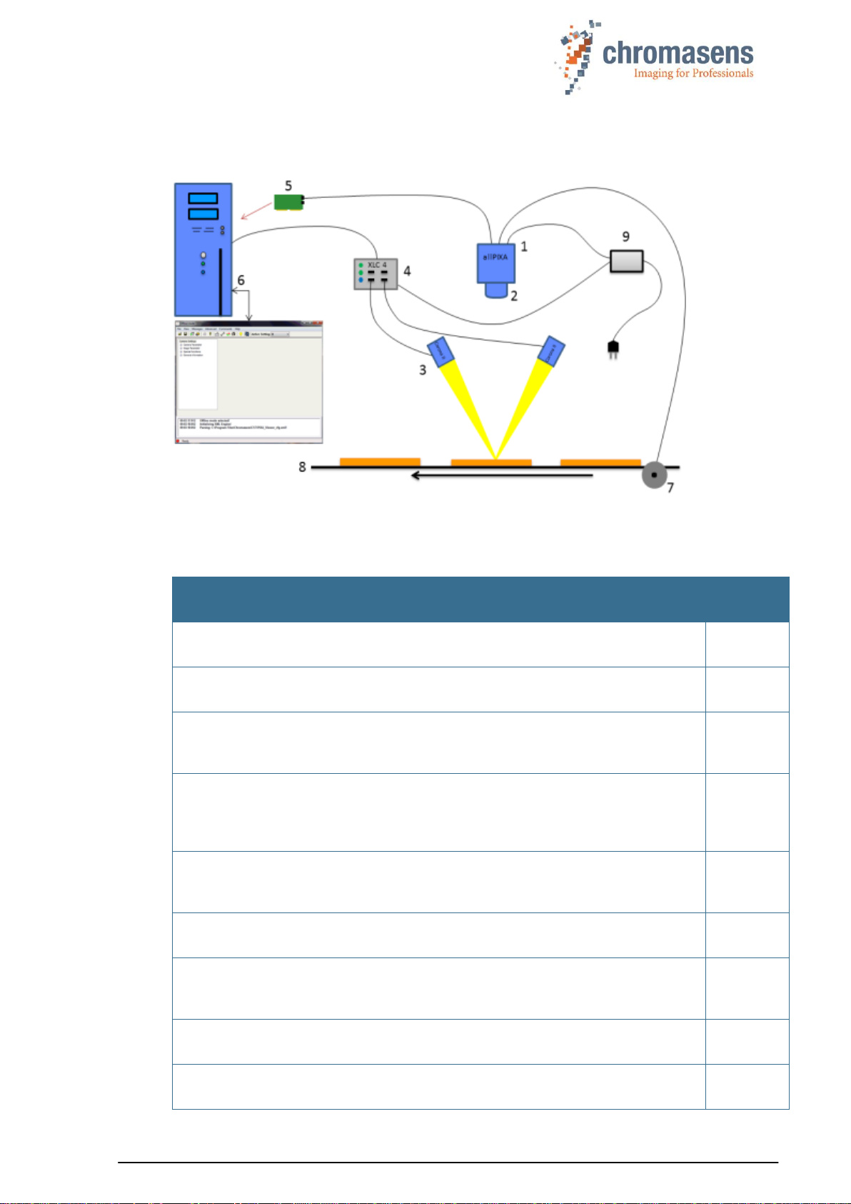
1.7 Design of a line scan camera system
The following figure demonstrates the basic setup of a typical line scan camera system:
Figure 1: Design of a line scan camera application
The following components are necessary in a typical line scan camera application:
Component
No.
Line scan camera: An allPIXA wave camera, which scans the image line by line
and communicates with the frame grabber (5, PC plug-in card).
1
The optical system: Optical lenses with tubes and mounts with an adjusted
focusing
2
Illumination: The illumination system lights up the information carrier/scan area
on the passing object. The Chromasens Corona II illumination system is an ideal
supplementary option for the allPIXA wave camera.
3
Illumination controller: Controls and monitors the illumination unit. The
Chromasens Corona II illumination (3) has integrated temperature/voltage
sensors which can be read out with the XLC4 controller. By use of the XLC4
controller, the illumination unit can be monitored and kept stable.
4
Frame grabber (PC plug-in card): The image data are sent to a PC by use of a
frame grabber with a Camera Link interface. The frame grabber establishes the
necessary hardware connection to the PC (6).
5
PC: The PC system performs subsequent processing of the image data and can
optionally control the illumination system (3 + 4).
6
Speed detection: The speed of the object / conveyor belt can be detected by an
optional incremental encoder. The encoder can be connected either to the
allPIXA wave camera or to the frame grabber.
7
Conveying unit: The conveying unit moves the scanned object past the allPIXA
wave camera.
8
Power supply: Both, the allPIXA wave camera and the illumination system,
require a suitable power supply.
9

Chromasens allPIXA wave - CD40172 Version 1.0 13
2 Specifications and definitions
The allPIXA wave camera family is available in the following maximum resolutions:
10,240 pixels
15,360 pixels
The allPIXA wave camera comprises all functions required for supplying images with the same
color, brightness and resolution of each operational area.
The allPIXA wave camera is especially suitable for inspection systems requiring a very high
speed and a consistently high color quality.
Continuous white balancing is possible during image acquisition to ensure optimum color
quality. In addition, offset and shading correction ensure the balance of different color pixel
sensitivities (DSNU and PRNU) as well as the illumination process.
Via frame grabber the incremental encoder can be either sent to the CC bits of the Camera
Link interface or directly connected to the allPIXA wave camera. As a result, images with a
consistent quality can be generated even at transport speeds with a high fluctuation rate.
The allPIXA wave camera parameters can be configured with the Camera Setup Tool (CST).
Equipped with a Camera Link base / medium / full interface support, the allPIXA wave camera
achieves a data rate in medium mode of up to 170 megapixels per second with 24 bit RGB,
which is equal to 510 Mbytes/s. With Camera Link Full_64 interface the data rate is 680
Mbytes/s and with Camera Link Full_80 interface the data rate is 850 Mbytes/s
The design was fully revised during development of the housing, which is impressively tough
but offers a number of screw mounting options. Take notice that the wide range of adapter
options makes the installation simple for users.
The standard mount connections M72x0.75 for the 10k camera, or M95x0.75 for the 15k
camera, respectively, permit to use all commercially available standard lenses. In addition,
special adapters are available that permit to connect Chromasens accessories.

Chromasens allPIXA wave - CD40172 Version 1.0 14
2.1 Camera highlights
Quadlinear color line scan camera (quadlinear CMOS line scan sensor)
5,6 µm pixel size
High accuracy sensor alignment
24 bit (3 x 8/12 Bit) color information or 1 x 8/12 Bit mono information on the output side
RGB spatial compensation in the camera (also sub-pixel correction, patented)
Continuous white balancing maintains a constant image brightness and color irrespective
of the temperature and service life of the illumination system
Incremental encoder port on the camera; this ensures simple handling and less
programming work
Shading correction, fully automatic calculation internally in the camera or optionally
calculated offline with CST
Gamma correction, brightness and contrast controller, separate for each channel
Multiple Color conversion matrix (CCM) and offset supported
Internal keystone correction for multiple angle positioning of the camera
Precise multi-camera synchronization
Automatic insertion of machine and camera data inside the image (for example, scanning
speed, CRC, time stamp, Encoder position,..)
Fully synchronized multi-channel LED flash control
Robust metal housing
Adjustable Camera Link clock
Mono-image output at individual color weights
Standard mount connections M72x0.75 for the 10k camera, or M95x0.75 for the 15k
camera, respectively
Special adapters permit to use Chromasens accessories
Internal test image generator
Option for area scanning with trigger inputs (light barriers)
2.2 Camera speed for available Camera Link modes and frequency
The allPIXA wave maximum line frequency depends on the selected Camera Link type and
frequency. For information about different configurations, see the tables below.
allPIXA wave 10k (10240 pixel):
Shown line frequencies are for full number of pixels, line frequencies in ROI mode are higher.
CL-Definition
Base
Mode
Medium
mode
Full64
mode
Full80_
8Tap_10Bit
Full80_
10Tap_8Bit
85.00 MHz
8.29 KHz
16.58 KHz
19.11KHz 1)
19.11 KHz 1)
19.11 KHz 1)
1) Values for the current camera prototypes. Values may increase in the future.
allPIXA wave 15k (15360 pixel):
Shown line frequencies are for full number of pixels, line frequencies in ROI mode are higher.
CL-Definition
Base
Mode
Medium
mode
Full64
mode
Full80_
8Tap_10Bit
Full80_
10Tap_8Bit
85.00 MHz
5.5 KHz
11.06 KHz
14.74 KHz
14.74 KHz
18.43 KHz

Chromasens allPIXA wave - CD40172 Version 1.0 15
2.3 Technical specification
Sensor
Quadlinear CMOS color line sensor
Pixel size
5,6 µm x 5,6 µm (5,6 µm pitch)
Line spacing
11,2 µm between R-G and G-B
Maximum pixel rate
226 megapixels/s 24 / 30Bit RGB
Maximum data rate on the Camera
Link
Base: 255 Mbytes/s
Medium: 510 Mbytes/s
Full_64 680 Mbytes/s
Full_80: 850 Mbytes/s
Resolution
5120 / 10240 / 15360px
Other sensor resolutions are available on request
Maximum line frequency Mono/RGB
(Preliminary)
10240 pixels: ##,# kHz / ##,#KHz
15360 pixels: ##,# kHz / ##,#KHz
Spectral sensitivity
360 nm to 960 nm
Video signal
8, 10 or 12 bit on the Camera Link,
4x12 bit ADC
Interface
Camera Link with up to 85 MHz
Line scan operating mode
Free-running / external trigger
(incremental encoder / line trigger)
Area scan operating mode
Image size either free-running, fixed, or based on
trigger pulse width
Other interfaces
Power supply (6 pin Hirose, male)
External IO (15 pin D-Sub, female)
Serial RS-232 (9 pin D-Sub, female)
Camera mount
M72x0.75 for allPIXA wave 10k,
M95x0.75 for allPIXA wave 15k,
Adapters to Chromasens accessories available
Certifications
CE, FCC compliant, RoHS
Power supply
12 to 24 VDC +/- 20 %; <19 W
Operating temperature
0°C to 60°C; 32°F to 140°F (housing temp.)
Housing dimensions
10k: L = 102 mm, H = 76 mm, D = 56 mm
15k: L = 102 mm, H = 56 mm, D = 56 mm
Weight
1.2 kg
NOTE
Depending on the power supply, the power consumption might be up to
1 ampere@24V at power-up for a short time. It is recommended to provide a
power supply with 24VDC/1amp or with higher possible power consumption.

Chromasens allPIXA wave - CD40172 Version 1.0 16
2.4 Mechanical specification
2.4.1Mechanical dimensions of the allPIXA wave 10k camera
Figure 2: Mechanical dimensions of the allPIXA wave 10k camera
NOTE I
Drawings and 3D-CAD-models are available on our homepage
http://www.chromasens.de/user
NOTE II
The shown position of the Sensor surface is given as resulting optical value
including lengthening of the sensor glass.
NOTE III
For information about the XYZ coordinate system and sensor alignment, see
section 2.5.

Chromasens allPIXA wave - CD40172 Version 1.0 17
2.4.2Mechanical dimensions of the allPIXA wave 15k camera
Figure 3: Mechanical dimensions of the allPIXA wave 15k camera
NOTE I
Drawings and 3D-CAD-models are available on our homepage
http://www.chromasens.de/user
NOTE II
The shown position of the Sensor surface is given as resulting optical value
including lengthening of the sensor glass.
NOTE III
For information about the XYZ coordinate system and sensor alignment, see
section 2.5.

Chromasens allPIXA wave - CD40172 Version 1.0 18
2.5 Sensor alignment and orientation
Sensor orientation and alignment in viewing from the front side of the camera. For adetailed
mechanical drawing, see section 2.4.
First pixel of sensor lines:
Left de
Color lines orientation:
Blue: top
Green: center
Red: bottom
Sensor alignment:
Position:
X: < +/- 100 µm
Y: < +/- 100 µm
Z: < +/- 100 µm
Rotation about:
Y: < +/- 0.1 °
Z: < +/- 0.1 °
Planarity of sensor surface:
< +/- 0.50 µm
Sensor window:
Thickness: 0.7 mm
Refraction index 1.5
Optical path extension: 0.24 mm
Sensor alignment is an important issue for:
Adjusting multi-camera systems
Replacing cameras
Mechanical design of the mounting system for the camera
First pixel
X
Y
Z

Chromasens allPIXA wave - CD40172 Version 1.0 19
2.6 Adapter and accessories
2.6.1Lenses adapters and mounts
Chromasens offers a large variety of accessories which are designed to provide maximum
flexibility and to get most out of the camera.
For the allPIXA wave cameras, special adapters are available that permit to use the
accessories of the allPIXA pro cameras, which are listed in the following sections.
You can find the complete list of all accessories including descriptions and detailed drawings
in the login area of our website at www.chromasens.de/user.
NOTE
For more information about accessories, refer to the corresponding
accessories catalogue or the configuration sheet at our website
www.chromasens.de/en/product/cmos-color-line-scan-camera-allpixa-wave-
10k.

Chromasens allPIXA wave - CD40172 Version 1.0 20
2.6.2Accessories for the allPIXA pro 2k & 4k camera S-Series
Figure 4: configuration scheme (housing type S)
Description
ID & Code
allPIXA pro - 4k
CP000476-4096-S
allPIXA pro - 4k with F-Mount
CP000482-0002
allPIXA wave camera Tubes 4k
Identification No.
Pos.
allPIXA camera-Tube-4k 20 mm
CP000389
01
allPIXA camera-Tube-4k 40 mm
CP000390
01
allPIXA camera-Tube-4k 60 mm
CP000391
01
allPIXA camera-Tube-4k 80 mm
CP000392
01
allPIXA camera-Tube-4k 100 mm
CP000393
01
allPIXA wave camera 4k direct mount Adapters
Identification No.
Pos.
allPIXA camera F-Mount Adapter
CP000385
02
allPIXA camera C-Mount-Adapter
CP000387
02
allPIXA camera 4K-Adapter M42x1-A45,46
CP000434
02
allPIXA camera Adapter-MF (to Modular Focus )
CP000386
02
allPIXA camera Adapter-M42x0,75 (to Schneider Unifoc
58 (T2))
CP000461
02
allPIXA camera Adapter-V-Mount
(to Schneider Unifoc 12 (V-Mount))
CP000462
02
allPIXA wave camera 4k additional parts
Identification No.
Pos.
Additional parts (custom specific)
only on request
03 - 06
The complete list of all accessories including descriptions and detailed drawings you can find
on our website www.chromasens.de/users.
Other manuals for allPIXA
1
Table of contents
Other chromasens Digital Camera manuals


