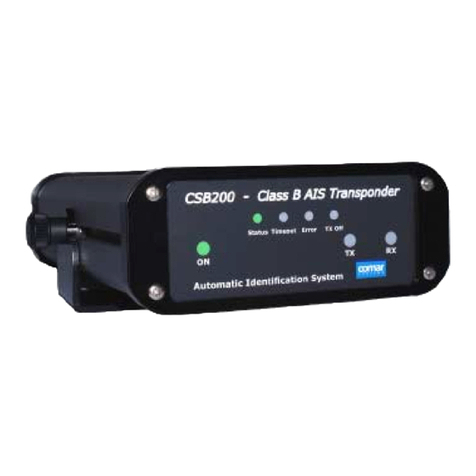
Chronelec Protime LS User manual

guide d’installation des transpondeurs
www.itschrono.comwww.itschrono.com
ITS Chrono 23, rue du Comté de Montbéliard 25660 MONTFAUCON - FRANCE - +33 (0)3 81 57 52 09 [email protected]om
ls filaire wired ls
ls rechargeable chargeable ls
V1
RÉF. TCTLSF / TCTLSB3
• Vitesse max. de détection.............................................................................200 km/h
• Max. detection speed........................................................... 200 km/h / 124,3 mph
• Température d’utilisation.............................................................. de -20°C à +70°C
• Temperature Range......................from -20°C to +70°C / from -4°F to +158°F
• Poids................................................................................................................................... 80 g
• Weight ..............................................................................................................80 g / 2,8 oz
CARACTÉRISTIQUES TECHNIQUES
TECHNICAL SPECIFICATIONS
• Câble blanc ou rouge ...............................................................................................+ 12 V
• White or red wire........................................................................................................+ 12 V
• Câble noir ou bleu........................................................................................................... 0 V
• Black or blue wire............................................................................................................0 V
• Consommation électrique...........................................................................12 mA max
• Power consumption .......................................................................................12 mA max
La LED clignote 4 fois toutes les 10 s si l’alimentation 12 V est OK.
The LED flashes 4 times every 10 s if the 12 V supply is OK.
ELECTRICAL SPECIFICATIONS / WIRED LS
CARACTÉRISTIQUES ÉLECTRIQUES / LS FILAIRE
VOITURE
MOTOCROSS
KARTCROSS
KARTING
QUAD
CAR
MOTOCROSS
KARTCROSS
KARTING
QUAD
ELECTRICAL SPECIFICATIONS / CHARGEABLE LS
CARACTÉRISTIQUES ÉLECTRIQUES / LS RECHARGEABLE
CLIGNOTEMENT FLASHING LED AUTONOMIE - AUTONOMY
TÉMOIN DE CHARGE
CHARGING INDICATOR
AUTONOMIE
AUTONOMY
4 fois / 10s 4 times / 10s 75 100 %
3 fois / 10s 3 times / 10s 50 75 %
2 fois / 10s 2 times / 10s 25 50 %
1 fois / 10s 1 time / 10s 10 25 %
1 fois / 10s 1 time / 10s 0 10 %
CHARGE
CHARGE
PERMANENT COMPLÈTE FULL
PERMANENT EN COURS CHARGING
42 mm
1,65 inches
75 mm
2,95 inches
21 mm
0,82 inches
41 mm
1,61 inches
70 mm
2,75 inches
79,5 mm
3,11 inches
23 mm
0,9 inches
28mm
1,1 inches
52 mm 2,04 inches
Ø 4 mm Ø 0,16 inches
84 mm
3,3 inches
21 mm
0,82 inches
Ø 4 mm
Ø 0,16 inches
Le transpondeur LS FILAIRE doit avoirsa propre
alimentation 12V (continu).
The WIRED LS transponder must have its own
power supply 12V (continuous).
Le transpondeur comporte 4 trous de fixation
prévus pour des vis ou des rivets. FIXEZ-LE
AVEC UNE ENTRETOISE ADAPTÉE.
The transponderhas 4 mounting holes for screws
or rivets. INSTALL IT WITH AN APPROPRIATE
SPACER BRACE.
Le support du transpondeur comporte 4 trous
de fixation prévus pour des vis ou des rivets.
The transponder holder has 4 mounting holes
for screws or rivets.
Pour les formes cylindriques (tube, fourche...), il
est conseillé d’installer d’abord le support seul.
For cylindrical shapes (tube,fork...), it is advisable
to first install the support alone.
Le transpondeur LS RECHARGEABLE doit être
rechargé avant tout meeting ou course. Une
charge continue de 18h minimum (100%) est
nécessaire pour 5 jours d’autonomie.
The CHARGEABLE LS transponder must be
fully charged before any meeting or race. A
continuous charge of minimum 18h (100%) is
necessary for a 5 days autonomy.
18H
DE CHARGE
18H CHARGING
5 JOURS
D’AUTONOMIE
5 DAYS OF AUTONOMY
GARANTIEGARANTIE
3
ANS
TCTLSF
TCTLSB3
LS FILAIRE / WIRED LS
LS RECHARGEABLE
CHÂSSIS
VÉHICULE
VEHICLE
CHASSIS
ENTRETOISE
SPACER BRACE
RCS 478 772 296 - Besançon - © 2019 ITS CHRONO

www.itschrono.comwww.itschrono.com
VOITURE (CAR)
MOTOCROSS
KARTCROSS / BUGGY
KARTING
QUAD
90°
60 cm max
0,4 inches
60 cm max
0,4 inches
90°
60 cm max
0,4 inches
90°
LE TRANSPONDEUR DOIT ÊTRE FIXÉ
AUDESSOUS DE LA PLAQUE
D’IDENTIFICATION DE LA FOURCHE.
AU POINT LE PLUS BAS
(60 cm max. du sol, les flèches du
transpondeur en direction de la piste).
THE TRANSPONDER MUST BE
INSTALLED BELOWTHE IDENTIFICATION
NAMEPLATE OF THE FORK.
TO THE LOWEST POINT
(max. 60 cm from the ground, the
arrows of the transponder in the direction
of the track).
LE TRANSPONDEUR DOIT ÊTRE FIXÉ
À L’AVANT DU KARTCROSS.
AU POINT LE PLUS BAS
(60 cm max. du sol)
• À 90° DU SOL (flèches du transpondeur
en direction de la piste).
THE TRANSPONDER MUST BE
INSTALLED AT THE FRONT OF THE
KARTCROSS.
TO THE LOWEST POINT
(max. 60 cm from the ground)
• AT 90° TO THE GROUND (arrows of the
transponder in the direction of the track).
LE TRANSPONDEUR DOIT ÊTRE FIXÉ
DANS LE PASSAGE DE ROUE AVANT
DE LA VOITURE.
• AU POINT LE PLUS BAS
(60 cm max. du sol)
• À 90° DU SOL (flèches du transpondeur
en direction de la piste).
THE TRANSPONDER MUST BE
INSTALLED IN THE FRONT WHEEL
ARCH OF THE CAR.
TO THE LOWEST POINT
(max. 60 cm from the ground)
• AT 90° TO THE GROUND (arrows of the
transponder in the direction of the track).
LE TRANSPONDEUR DOIT ÊTRE FIXÉ
DERRIÈRE LE CARÉNAGE.2 POSITIONS
POSSIBLES.
AU POINT LE PLUS BAS
(60 cm max. du sol)
• À 90° DU SOL (flèches du transpondeur
en direction de la piste).
THE TRANSPONDER MUST BE
INSTALLED BEHIND THE FAIRING. 2
POSSIBLE POSITIONS.
TO THE LOWEST POINT
(max. 60 cm from the ground)
• AT 90° TO THE GROUND (arrows of the
transponder in the direction of the track).
Axe de la fourche
Axis of the fork
VÉRIFIEZ LA BONNE INSTALLATION ET L’ALIMENTATION ÉLECTRIQUE DE VOTRE TRANSPONDEUR AVANT CHAQUE COURSE. CHECK THE CORRECT INSTALLATION AND THE POWER SUPPLY OF THE TRANSPONDER BEFORE EACH RACE.
MERCI DE SUIVRE ATTENTIVEMENT LES INSTRUCTIONS D’INSTALLATION AVANT UTILISATION. LA BONNE
INSTALLATION DE VOTRE TRANSPONDEUR EST PRIMORDIALE CAR L’ONDE ÉMISE EST DIRECTIONNELLE.
PLEASE CAREFULLY FOLLOW THE INSTALLATION INSTRUCTIONS. THE PROPER INSTALLATION OF YOUR
TRANSPONDER IS ABSOLUTELY NECESSARY BECAUSE THE RADIO SIGNAL IS DIRECTIONAL.
LE TRANSPONDEUR DOIT ÊTRE FIXÉ
À L’AVANT DU QUAD.
AU POINT LE PLUS BAS
(60 cm max. du sol)
• À 90° DU SOL (flèches du transpondeur
en direction de la piste).
THE TRANSPONDER MUST BE
INSTALLED AT THE FRONT OF THE
QUAD.
TO THE LOWEST POINT
(max. 60 cm from the ground)
• AT 90° TO THE GROUND (arrows of the
transponder in the direction of the track).
1
90°
60 cm max
0,4 inches
À L’AVANT DU KART
AT THE FRONT OF THE KART
90°
2SUR LE CÔTÉ DU KART
ON THE SIDE OF KART
LE TRANSPONDEUR NE DOIT JAMAIS ÊTRE FIXÉ DIRECTEMENT SUR UNE PIÈCE EN CARBONE OU EN
MÉTAL. AUCUNE PARTIE EN MÉTAL OU EN CARBONE NE DOIT SE TROUVER ENTRE LE TRANSPONDEUR ET
LA PISTE. POUR CELA, FIXEZ LE TRANSPONDEUR AVEC LE SUPPORT D’ORIGINE LS RECHARGEABLE OU UNE
ENTRETOISE ADAPTÉE AU DÉBORD SOUHAITÉ LS FILAIRE. TOUT AUTRE SENS, ANGLE OU ENDROIT DE
FIXATION UTILISÉ POUR LE TRANSPONDEUR ENTRAÎNERAIT DES RISQUES DE NON-DÉTECTION SUR LA
BOUCLE DE CHRONOMÉTRAGE.
THE TRANSPONDER MUST NEVER BE INSTALLED DIRECTLY ON A CARBON OR A METALLIC PIECE. ANY METAL
OR CARBON PART SHOULD NEVER BE BETWEEN THE TRANSPONDER AND THE TRACK. FOR THAT, INSTALL THE
TRANSPONDER WITH THE SPECIFIC HOLDER CHARGEABLE LS OR AN APPROPRIATE SPACER BRACE FOR
THE DESIRED OVERHANG WIRED LS. EVERY OTHER DIRECTION, ANGLE, BRACKET OR MOUNTING AREA
USED FOR TRANSPONDER WOULD ENTAIL RISKS OF NON-DETECTION ON THE TIMING LOOP.
This manual suits for next models
2


