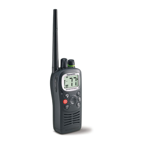
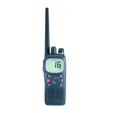
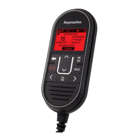
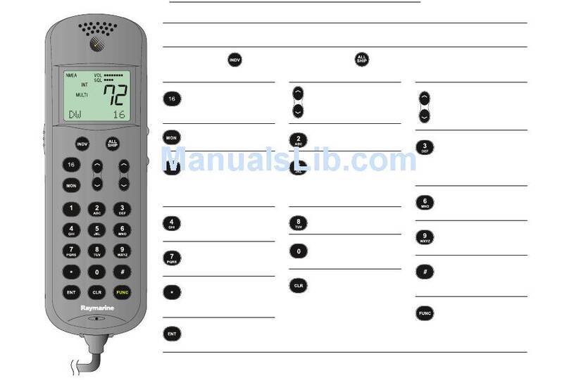
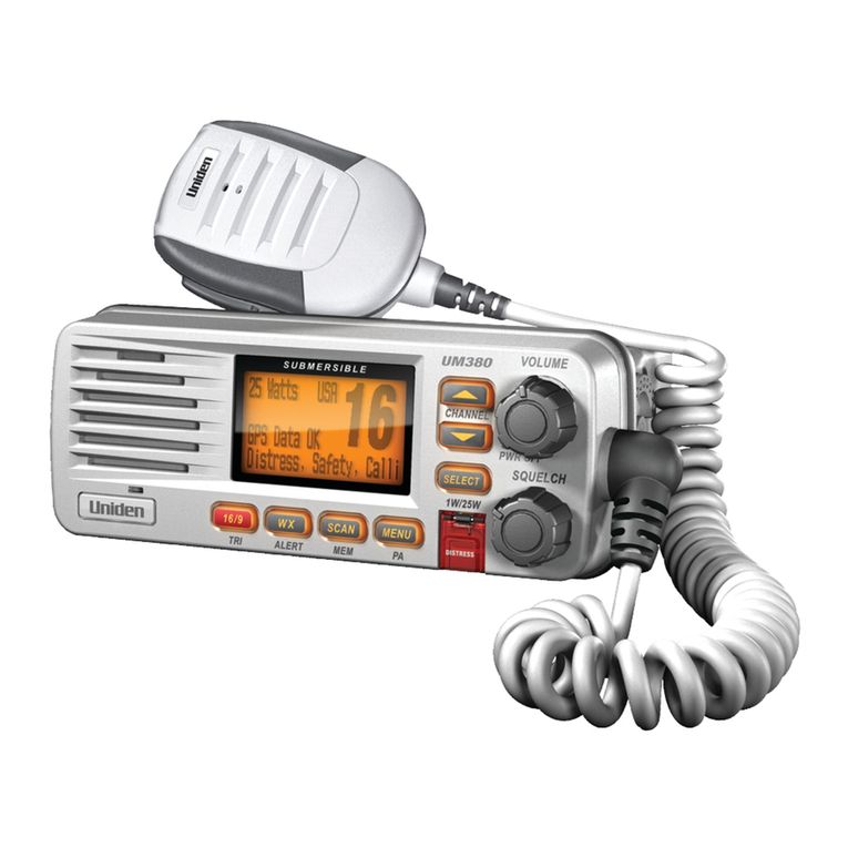
Raymarine Ray54E User guide

Ray54E
Marine
VHFRadio
Owner’sHandbook
Documentnumber:81232-3
Date:July2005


iii
AboutthisHandbook
Introduction
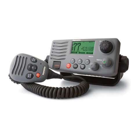
Thishandbook describesthe Ray54E fixedVHF marine radio.The Ray54E
providestwo-waycommunicationsonall Internationalmarine channels,
pre-setprivate channels, and(if programmed)all USand Canadian and
marinechannels. TheRay54Eincludes equipment for Class “D” Digital
SelectiveCalling (DSC).
ConventionsUsed
Throughoutthishandbook, thededicated(labelled)keys are shown in bold
capitals(for example:SCAN/SAVE). The LCD indicators and functions are
shown in normal capitals(forexample:TX).
➤Operatingprocedures, which may consist ofa single key-press ora
sequenceofnumberedsteps,areindicatedbyanarrow iconshowninthe
margin.
TechnicalAccuracy
Tothebestofourknowledge,theinformationinthishandbookwascorrectas
itwent to press.However, ourpolicy ofcontinuous productimprovement
and updating may change specifications without priornotice. As a result,
unavoidabledifferencesbetweentheproductandhandbookmayoccurfrom
timeto time. Raymarinecannot accept liability foranyinaccuracies or
omissionsit may contain.
Forthe latest productinformation visitour website:
www.raymarine.com
Warranty
ToregisteryournewRaymarineproduct,pleasetakeafewminutestofillout
thewarranty registrationcard foundat the end ofthis handbook.It is very
importantthatyoucompletetheownerinformationandreturnthecardtothe
factoryin orderto receive full warrantybenefits.
Raymarine is a registered trademarkof Raymarineplc.
© Raymarine plc 2005

iv Ray54E VHF Radio
ImportantInformation
MaritimeMobileServiceIdentity(MMSI)
TheRay54E includesequipment for Class“D” Digital Selective Calling
(DSC). A nine-digit Maritime Mobile Service Identity(MMSI) number is
requiredto operate theDSC equipment.In some areas, a radiooperator
licenceisrequired before anMMSI number willbe issued.
Note: YoucanrequestanMMSInumberfromsameagencythatissuesradio
or Ship Radiolicences in your area. Onceobtained, you can program the
MMSI number into your Ray54E asdescribed in thishandbook.
GroupMMSIID
AGroupID MMSInumber canalsobe entered forvessels that arepart ofa
group,suchasaflotillaorracingfleet,enablingDSCcommunicationswithin
thegroup.
AutomaticTransmitterIdentificationSystem(ATIS)
Ifyou purchasedyourRay54E toincludeuse onthe inlandwaterwaysofthe
contractinggovernmentsof the“Regional Arrangement Concerning the
Radiotelephone Service on Inland Waterways”— also known as the Basel
Agreement1— yourRay54E willbe programmedby your dealer toinclude
AutomaticTransmitter IdentificationSystem(ATIS)functionality.ATIS
includes data at the endof radio transmission that identifiesyourstation.
ATISoperationcanbeturnedonoroffasneededviatheradio’sMenumode.
Note: WhenATIS isenabled, certainprogrammingsteps have been imple-
mented to protect the integrity ofthe Basel Agreement, including the block-
ingof DSC functionswhenATIS is active.SeeDigital SelectiveCalling
(DSC)on page 31and ATIS Functionon page 79.
YourATISIDnumber is derivedfrom yourvessel’s callsign. Your
authorized Raymarine dealer can assistyouin decodingyour ATIS ID
number,which youcan then programinto your Ray54Eusing the operation
describedon page77.
1.The Basel Agreement includes Germany, Austria, Belgium, Bulgaria, Croatia,
France, Hungary, Luxembourg, Moldova, the Netherlands, Poland, Romania, Rus-
sian Federation, the Slovak Republic, Switzerland, the Czech Republic, Ukraine and
the Federal Republic of Yugoslavia.

v
SAFETYNOTICE
YourRaymarine VHF radio generatesand radiates radio frequency (RF)
electromagnetic energy(EME). This equipmentmust be installedand
operatedin accordancewiththeinstructionscontainedin thishandbook.
Failure to do socan result in personal injury and/or product malfunction.
CAUTION: NavigationAid
Thisunitis onlyanaidtonavigation.Itsaccuracycan beaffectedby
manyfactors,including equipmentfailureordefects, environmental
conditions,and improperhandlingoruse.Itisyour responsibilityto
exercisecommonprudenceand navigationaljudgments. Do notreply
uponthisradio as a substituteforsuchprudenceand judgment.
AntennaMountingandEMEExposure
Foroptimal radioperformance and minimalhumanexposuretoradio
frequency electromagnetic energy, make sure the antennais:
• connected to the radio before transmitting
• located where it will beaway from people
• locatedat least 1.5metres(5 feet)from the radio’s mainunit
SafeCompassDistance
SafeCompassDistanceis1meter foracommonmechanicalcompass;other
compasstypes may require greaterdistances. To be sure, you should locate
theradioas far as possible fromthe compass. Test your compass toverify
proper operation while the radiois alsooperating.
EMCConformance
All Raymarine equipment and accessoriesare designed to the best industry
standardsforuse in the recreationalmarineenvironment. Theirdesign and
manufacture conform to the appropriate Electromagnetic Compatibility
(EMC) standards but correctinstallation and use is requiredto ensure that
performanceis not compromised.
ProductDisposal
Whenyouwanttodisposeofthisproductattheendofitsworkinglife,please
do so in accordance withlocalregulations.

vi Ray54E VHF Radio

vii
Contents
AboutthisHandbook...........................................................................................iii
Introduction .............................................................................................iii
Conventions Used ...................................................................................iii
TechnicalAccuracy .................................................................................iii
Warranty ..................................................................................................iii
ImportantInformation ........................................................................................iv
MaritimeMobileService Identity (MMSI) .............................................iv
AutomaticTransmitter Identification System (ATIS) .............................iv
SAFETYNOTICE ...................................................................................v
Product Disposal .......................................................................................v
Chapter1: Introduction .......................................................................................1
1.1 Ray54E Fixed StationVHF Radio ...................................................1
1.2 Features ............................................................................................1
Chapter2: Installation .........................................................................................3
2.1 Unpacking andInspection ................................................................3
EquipmentSupplied .....................................................................3
2.2 PlanningtheInstallation ...................................................................4
TypicalMounting Methods ..........................................................4
FlushMounting.............................................................................4
2.3 PowerConnections ..........................................................................6
2.4 ExternalSpeakerConnections .........................................................7
2.5 Grounding ........................................................................................7
2.6 GPS/NMEA Data .............................................................................7
2.7 Antenna Connections .......................................................................8
Chapter3: GettingStarted ..................................................................................9
3.1 Keypad andRotaryKnobs ...............................................................9
MicrophoneKeys .......................................................................10
MainUnitRotary Keys ...............................................................10
MainUnitPush Keys ..................................................................10
Microphone ................................................................................ 11
1. PTT .................................................................................... 11
2. UP/DOWN ........................................................................ 11
3. 16/PLUS ............................................................................ 11
4. HILO ................................................................................. 11
Main Unit .................................................................................... 11
5. CH ..................................................................................... 11
6. PWR/VOL ........................................................................ 11
7. SQ ..................................................................................... 11
8. DW/TRI ............................................................................ 11

viii Ray54E VHF Radio
9.CALL/MENU ...................................................................12
10.HILO/USER ...................................................................13
11. SCAN / SAVE .................................................................13
12.16/PLUS..........................................................................14
13.CLEAR ...........................................................................14
14.DISTRESS ......................................................................14
3.2 LCDDisplay ..................................................................................14
1.(HI/LO)TX Power ..................................................................14
2.(TX)Transmitting ...................................................................14
3.(RX)Receiving .......................................................................15
4.(LOCAL)Local/Distant Mode ...............................................15
5. DSCMessage .........................................................................15
6.ATIS Active ............................................................................15
7.NOGPS ...................................................................................15
8.BatteryLow ............................................................................15
9. (USER) Favourite ChannelMode ...........................................15
10.(SAVED)Memory Mode ......................................................15
11. (WX) WeatherChannel .........................................................15
12.(ALERT) WeatherAlert ........................................................15
13.(UI C) Channel Set ...............................................................16
14.(A)Simplex Channel ............................................................16
15.(B)Receive-only Channel ....................................................16
16.ChannelNumber ...................................................................16
17.DotMatrix Display ...............................................................16
Chapter4: GeneralOperations .........................................................................17
4.1 Turning the PowerON andOFF .....................................................17
4.2 SettingtheVolume .........................................................................17
4.3 SettingtheSquelch .........................................................................17
4.4 Setting the Power Output ................................................................17
4.5 SettingtheChannel ........................................................................18
Onthemicrophone... .............................................................18
Onthemain unit... .................................................................18
4.6 SelectingaWeather Channel(IfAvailable) ...................................19
WeatherAlertOperation (If Available) .................................20
4.7 SelectingthePriority Channel ........................................................20
4.8 SelectingtheSecondary Priority (PLUS) Channel ........................21
ReprogramingtheSecondary Priority (PLUS) Channel ............22
4.9 Transmitting ...................................................................................23
4.10 Using the ScanModes ....................................................................23
AllScan .......................................................................................24
Saved(Memory) Scan ................................................................24
PriorityAllScan .........................................................................25

ix
Priority SavedScan .....................................................................25
4.11 Adding Channels toMemory .........................................................26
4.12 UsingtheMonitor Modes ...............................................................27
DualWatch .................................................................................27
Tri Watch.....................................................................................28
4.13 USER Channel Mode .....................................................................29
4.14 DSCCallOperation .......................................................................29
4.15 Menu Mode Operation ...................................................................30
Chapter5: DigitalSelectiveCalling(DSC).......................................................31
5.1 DSC CallFunction .........................................................................32
5.2 Individual Calls ..............................................................................34
MakingDSCCalls to Coast Stations ..........................................34
Transmitting an IndividualCall ..................................................34
Receiving Individual Calls .........................................................37
5.3 Group Calls ....................................................................................38
Transmitting a Group Call ..........................................................38
Receiving GroupCalls ................................................................40
5.4 All ShipsCalls ................................................................................42
Transmitting an All ShipsCall ....................................................42
Receiving an AllShips Call ........................................................43
5.5 Distress Calls ..................................................................................45
SendingaDistress Call ...............................................................45
Undesignated(Quick)Distress Call .....................................46
DesignatedDistressCall .......................................................46
CancellingaDistress CallMade in Error ....................................48
Receiving a DistressCall ............................................................48
Receiving aDistressACK Sentfrom aCoast Station .................49
Receiving a DistressRelaySentbyAnotherStation ..................49
5.6 PositionRequest .............................................................................50
SpecifyingtheTargetVessel .......................................................50
RetrievingtheLast Received Position Data ...............................52
Receiving aPositionRequest From Another Station .................53
5.7 Call Log ..........................................................................................53
MakingaCall from a Call Log Entry ..........................................54
SavinganMMSIID Number from a Call Log Entry ..................55
5.8 DSC Distress Log ...........................................................................56
Chapter6: MenuSettings ..................................................................................57
6.1 Menu Function ...............................................................................57
6.2 DSC Phonebook .............................................................................59
AddinganEntry ..........................................................................59
EditinganExisting Entry ............................................................61
DeletinganExisting Entry ..........................................................62
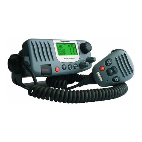
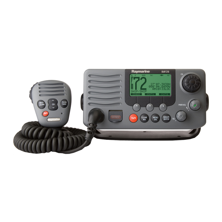
xRay54E VHF Radio
6.3 BacklightAdjustment ....................................................................63
6.4 ContrastAdjustment .......................................................................63
6.5 GPS/Time Setup .............................................................................64
WhenGPSInformation Not Available .................................64
6.6 Settings ...........................................................................................66
Latitude/LongitudeDisplay ........................................................67
Time Display ...............................................................................67
Time Offset .................................................................................68
Time Format................................................................................68
COG/SOGDisplay .....................................................................68
6.7 RadioSetup ....................................................................................69
Band ............................................................................................69
Channel(CH)Name ...................................................................70
DisplayName .......................................................................70
CHInfo .................................................................................70
DeletingaChannel Name Entry ...........................................70
RingVolume ...............................................................................70
KeyBeep.....................................................................................70
6.8 DSCSetup ......................................................................................71
MyMMSIID ..............................................................................72
GroupMMSI Setup ....................................................................73
AddingaNew Group ............................................................74
EditinganExisting Entry ......................................................76
MyATIS ID ................................................................................77
ATIS Function .............................................................................79
PositionReply .............................................................................81
Automatic ChannelChanging for Incoming Calls .....................82
6.9 ResettingFactory Defaults .............................................................84
Chapter7: CustomerService ............................................................................85
7.1 Howto Contact Raymarine ............................................................85
AppendixA:Specifications .................................................................................87
AppendixB:ChannelList .....................................................................................89
InternationalMarineVHFChannels & Frequencies.................. 89
EuropeanPrivate Channels and Frequencies ..............................92
WXChannels(North America only) ..........................................92
U.S.MarineVHFChannels and Frequencies............................. 93
CanadianMarineVHFChannelsandFrequencies .................... 96
AppendixC:Glossary .........................................................................................101
Index ................................................................................................103

Chapter 1: Introduction 1
Chapter1: Introduction
1.1 Ray54EFixedStationVHFRadio
TheRay54Emarine VHFradiotelephoneis a microprocessor-controlled
transceiverthatprovides reliablesimplex(single frequency)and semi-
duplex (two frequency) communications. This handbook describes the
physicalandfunctionalcharacteristics of the radio.
Figure1-1: Ray54EVHFRadio
TheRay54Eprovidestwo-way communications on all International marine
channels,pre-setprivatechannels,and(ifprogrammed)allUSandCanadian
marineand weatherchannels.RefertotheFrequencyTablesinAppendixB,
which list allmarine VHF channels available in your radio. You should
familiarizeyourself with thesetables to ensure properchannelusage.
1.2 Features
TheRay54Eisdesignedandmanufacturedtoprovideeaseofoperationwith
excellentreliability. The Ray54Ehas many enhanced features, including:
• Waterproofto IPX-7 standard
• Anti-glare2" x 1.5"LCD with 4x 12 dot matrixdisplay
• Nine(9) brightnessand contrastadjustments
• Dedicated key for switchingto PriorityChannel 16

2Ray54E VHF Radio
• Programmable SecondaryPriority(PLUS)Channel key
• ATIS operation, ifrequired
• Private Channels (if so licensed)
• AllScan, Memory Scan and 2 Priority Scan functions
• Dual/Tri Watch Monitor modes
• Eachchannel displaysan editable 12-characterChannelName
• Enhanced GPS PositionData gives Latitude andLongitude to 1/10,000
ofa minute plusTime,SOGand COG datafrom any NMEA input
• AutomaticallydistinguishesbetweencallsmadetoShiporCoastStations
• LowandHigh Voltage detection with alarm
• User Mode provides easy access to favourite channels
• KeyBeep volumeadjustment(3levels)
DigitalSelectiveCalling(DSC)
TheRay54E includesequipment for Class“D” Digital Selective Calling
(DSC). DSC protocol is a globally applied system used to send and receive
digitalcalls.DSC uses a uniqueMaritime Mobile Service Identity (MMSI)
numberto direct DSC callsdirectlyto yourradio, muchlike a telephone
number.WhentheDSC signalisreceived, theradio quicklyswitchesover to
channel70 and performsthecorrespondingoperation.
Note: AnMMSInumberisrequiredtooperatetheDSCequipmentinthisra-
dio.You canrequestan MMSI number from the same agency thatissues ra-
dioorShipRadiolicencesinyourarea.Onceobtained,youcanprogramthe
MMSInumberyourselfone timeonlyusingthemenuoperationdescribedin
MyMMSIID on page 72.
TheRay54E includesthe followingDSC features:
• Separate receiver dedicatedtohandling DSC Calls on channel 70
• PositionRequestfunctionsendsGPSpositiondatatoorreceivesposition
datafrom other stations
• Phonebookforautomaticallymaking DSC calls
• QuickSavefeaturesavesincomingDSCCallsandthecaller’sassociated
MMSInumberdirectlyinto thephonebook
• QuickCallfeaturesends IndividualCalls orGroupCalls directlyfrom
thephonebook, justlike theredialfunctionona telephone
• Three(3)GroupIDsformakingDSCCallsonlytostationsinyourgroup,
suchasa flotilla orfishing fleet
DSCfunctionsarefully describedinChapter 5:

Chapter 2: Installation 3
Chapter2: Installation
2.1 UnpackingandInspection
Use care when unpacking the unit fromthe shipping carton toprevent
damageto the contents.It is alsogoodpracticeto save thecartonand the
interiorpacking materialinthe event you must return the unit to the factory.
EquipmentSupplied
The following is a list of materials supplied with the Ray54E:
The following is a of optional equipment for the Ray54E:
Table2-1: SuppliedComponents
PartNumber Description
E43024
E43025 Ray54E,White
Ray54E,CharcoalGray
81232 Handbook,Ray54E
R49108
R49128
R49133
Power Cord, Ray54E
GPSCable,Ray54E
SpeakerCord,Ray54E
R49093
R49095 MountingYokeforWhiteRay54E
MountingYokeforCharcoalRay54E
R49094
R49096 YokeKnobandSpacerforWhiteRay54E
YokeKnobandSpacerforCharcoalRay54E
R49104
R49105 MicrophoneBracketforWhiteRay54E
MicrophoneBracketforCharcoalRay54E
R49109
R49110 SunCover,White
SunCover,CharcoalGray
MountingHardware:
Screws(x4)forMountingYoke
Screws(x2)forMicrophoneBracket
Screw/LockWasher(x1)forGrounding
Table2-2: OptionalEquipment
PartNumber Description
E46034 FlushMountKit,ASeriesVHFRadios

4Ray54E VHF Radio
2.2 PlanningtheInstallation
Whenplanningtheinstallationof your Ray54E, consider thefollowing
conditionstoensure dependableand trouble-free operation.
Mountthemain unitto alloweasy accessfrom thelocationwhere theboat is
normallynavigated.
Themain unitis designed tobemounted horizontallyorvertically ona flat
bulkhead.Select a locationthat is non-metallic,dry, protected,well-
ventilated,andfree from high operatingtemperaturesand excessive
vibration. Provide sufficient space behind the main unit to allow for proper
cableconnections tothe rear panelconnectors. Locate the mainunit as near
as possible to the power source yet asfar apart as possible from anydevices
thatmaycause interference suchas motors,generators, andother on board
electronics.Theradioshouldbeprotectedfromprolongeddirectexposureto
rainandsaltspray.
The Ray54E is notdesigned tobe mountedin enginecompartments. Donot
installtheradioinalocationwheretheremaybeflammablevapours(suchas
in an engine room or compartment, orin a fuel tankbay), water splash or
sprayfrom bilgesorhatches, where itis at riskfromphysical damage from
heavyitems (such as hatch covers,toolboxes,etc.),orwhere it mightbe
covered by other equipment. Locate the radioat least 1.5meters from the
antenna.
SafeCompassDistanceis1meterfora commonmechanicalcompass;other
compasstypes may requiregreaterdistances.Tobe sure, youshouldlocate
theradioas far as possible from the compass. Testyour compass to verify
properoperationwhiletheradioisalsooperating.
TypicalMountingMethods
The Ray54E can beconvenientlymountedon a charttable, bulkhead,
overhead,or anyotherdesired location. Refer to the followingfigurefor
typicalmountingmethods.
FlushMounting
In addition tothe typicalMounting Methods, theRay54E may also be flush
mountedusing theoptionalE46034Flush Mount Kit.Instructionsfor
installingtheradiousingtheFlushMountKitareincludedwiththekit.These
kitsare available from yourRaymarinedealer.

Chapter 2: Installation 5
Figure2-1: TypicalMountingMethods
CAUTION:Makesuretherearenohiddenelectricalwiresorotheritems
behindthedesiredlocationbeforeproceeding.Check thatfreeaccess
formountingand cabling isavailable.
Figure2-2: MountingDimensions

6Ray54E VHF Radio
2.3 PowerConnections
TheredandblackPowerCordprovidesconnectiontoDCpower.Thered(+)
wire contains a 7amp in-line fuse. It should be connectedto the positive
terminalof the power source.The black (-) wire should be connected to the
negative(ground) ofthe power source.Checkthe polaritywith a VOM
(Voltage/OhmMeter)and reconnectobservingcorrectpolarity. Ifthefuse
ever needsto be replaced,be sure to use thesame type and rating.
Connectthestrippedwires on the Power Cordto the nearestprimarysource
oftheboat's DC power. Atypicalsourcewouldbe a circuitbreaker on the
powerpanel ora fuse blocknear the unit.The circuitbreakeror other in-line
fuse should berated at 10amps. The power cordshould be long enoughto
reachtheDC power source.If additionalwire length is required, the cable
canbeextended byadding more cableas necessary. However,forpower
cableruns longerthan15feet, largerwire diameter size should be used to
preventvoltageline loss. Toensure adequate current drawto theequipment,
Raymarinerecommends thatyouuse lugstoconnectthepower cable to the
DCsupplyandthatthe lugconnectionsbe both crimpedand soldered.The
connection terminal should be clean, with no sign of corrosion.
Afterthecordisconnectedtopower,slidethebulletconnectorsonthePower
Cordinto theirmates (withthesame coloured wire)onthe rear ofthe radio.
(SeeFigure 2-3 .)
TheRay54E is designedtobe operatedon a 12 volt(nominal)system. If
batteryvoltage dropsbelow10.5VDC (approximately),the icon
appearsonthe LCD(see page15). Discontinueusingthe radio ifa low
voltageconditionoccurs as performance wouldbe unreliable. Ifvoltage
exceeds16VDC,themessageEXCESSIVEVOLTAGEappearsonthedotmatrix
displayand an alarmis sounded. Immediatelydisconnectthe radioif a high
voltageconditionoccurs as theunitcould becomedamaged.
Figure2-3: WiringConnections

Chapter 2: Installation 7
2.4 ExternalSpeakerConnections
Locatedjustbelowthe power cord is a cable for connection to an optional
externalspeaker.Connectthewhite(+)wireandblack(–)wiretothespeaker
observingpolarityasitismarkedonthespeaker.Matetheconnectorwithits
counterpart on the rear of theradio. (See Figure 2-3 .)If not connecting an
external speaker, please leavethe dust cover on the cableconnector.
2.5 Grounding
Whilespecial groundingisnot generallyrequiredfor VHFradiotelephone
installations,itis goodmarine practicetoproperlygroundall electronic
equipmenttotheboat’searthgroundsystem.TheRay54Ecanbeconnectedto
groundbyinstallingthesuppliedscrew and lock washer in thethreadedhole
labelled GND on the main unit’s rear panel justbelow theantenna jack.Then
attacha wire fromthisscrew to thenearestship’s earth ground connection
point.The recommendedwireto beused forsuch groundingis#10AWG.
2.6 GPS/NMEAData
The Ray54E accepts NMEA0183 (V1.5) data from aposition determining
device (GPS) to provide the Latitude andLongitude position information
thatistransmittedduringaDSCDistressCall.WhenavalidNMEAsignalis
detected, the GPSindicatorappears on theLCD. When novalid NMEA
signal is detected, the NOGPSindicator appears.
Connect the NMEAOUT + and NMEA OUT– signals from the positioning
device to the GPS + (yellow)and GPS –(green) wires, respectively,of the
GPScable.Mate theconnectorwithitscounterparton therear ofthe radio,
aligningthe arrowson the two connectors.(See Figure 2-3 .)If not
connecting a GPS,please leave the dust cover onthe cable connector.
Anexampleofhowtomaketheconnectionsusingasuitableconnectorblock
is shown inthe following drawing. Forspecific instructions how toconnect
yourparticularGPS,pleaserefertothehandbookthatcamewiththatdevice.
Figure2-4: GPSWiring

8Ray54E VHF Radio
2.7 AntennaConnections
The coaxial VHF antenna cable connects tothe Ray54E antenna jack on the
rearpanel usinga PL259VHF typeconnector. Theantenna cablelengthcan
becriticaltoperformance.If youareuncertain, contacta professional
installer or callRaymarine ProductSupport. Ifa longer cablelength is
required,RG-8x (50 ohm) marine coaxial cable or equivalentcable can be
used for runs up to a maximum of 50 feet.If the distance required iseven
greater, Raymarinerecommends usinglow lossRG-213 orequivalent cable
for the entire run to avoid excessive losses in power output.
Iftheantenna RF connectoris likely to be exposed to the marine
environment,a protectivecoating ofgrease (Dow CorningDC-4 orsimilar)
canbeappliedto the connectorbefore connecting itto theradio. Anyother
extensionsor adaptersin the cablerun shouldalso beprotectedby silicon
grease and thenwrappedwith a waterproofing tape.
AntennaMountingSuggestions
Mounting the VHF antenna properly is veryimportant becauseit will
directly affectthe performance of your VHF radio. Use a VHFantenna
designedfor marinevessels.
Since VHF transmission is essentially line-of-sight, mount the antenna at a
locationon the vesselthat is freeofobstruction toobtain maximumrange.
Ifyoumustextendthe lengthof the coaxial cable between the antenna and
theradio,useacoaxialcabledesignedfortheleastamountofpowerlossover
theentirecablelength.
AntennaMountingandEMEExposure
Foroptimalradioperformance and minimalhuman exposure toradio
frequencyelectromagnetic energy, make sure theantenna is:
• connected to the radio before transmitting
• properlymounted
• located whereitwill beaway frompeople
• locatedat least 1.5 metres (5 feet)from the radio

Chapter 3: Getting Started 9
Chapter3: GettingStarted
3.1 KeypadandRotaryKnobs
Severalofthe keyson the front panelof the main unitserve multiple
purposes.Forthe mostpart, the functionindicatedon thefirst lineof thekey
is accessed by pressing and releasing thatkey. The function indicated on the
second line of the key is accessed by pressing and holding the key for three
seconds.
Figure3-1: Ray54EKeysLayout

10 Ray54E VHF Radio
MicrophoneKeys
MainUnitRotaryKeys
MainUnitPushKeys
KeyName Press&Release(<3sec.) Press&Hold(>3sec.)
1.PTT Push-to-Talk Push-to-Talk
2.UP/DOWN Channelincrement/decrementand
navigatingmenuitemselections Rapidchannelchangeandnavigating
menuitemselections
3.16/PLUS SwitchbetweenthePriorityand
WorkingChannels SwitchestoSecondaryPriority(PLUS)
channel;IfalreadytunedtothePLUS
channel,programsanewPLUSchan-
nel.
4.HI/LO TXPowerHigh/LowandACCEPTkey
formenuitemselections TXPowerHigh/LowandACCEPTkey
formenuitemselections
KeyName Function
5.CH/PUSH Rotatetoincrement/decrementchannelsornavigatemenuitem
selections
6.PWR/VOL PowerradioON/OFFandadjustvolumelevel
7.SQ Adjustsquelchthresholdlevel
KeyName Press&Release(<3sec.) Press&Hold(>3sec.)
5.CH/PUSH ACCEPTmenuitemselections ACCEPTmenuitemselections
8.DW/TRI DualWatchMode TriWatchMode
9.CALL/MENU ActivateDSCfunctions ActivateMenufunctions
10.HL/USER TXPowerHigh/Low USER(SavedMemoryChannel)Mode
11.SCAN/SAVE ScanON/OFF SAVE/DELETEchannelto/frommemory
12.16/PLUS SwitchbetweenthePriority
andWorkingChannels SwitchestoSecondaryPriority(PLUS)
channel;IfalreadytunedtothePLUSchan-
nel,programsanewPLUSchannel.
13.CLEAR Cancelfunction WeatherChannelMode,ifsoprogrammed
14.DISTRESS DesignateDistressType MakeDistressCall
Table of contents
Other Raymarine Marine Radio manuals

Raymarine
Raymarine Ray218 User guide

Raymarine
Raymarine Ray 90 User manual

Raymarine
Raymarine Ray 55E Owner's User guide

Raymarine
Raymarine RAY 210VHF User manual

Raymarine
Raymarine Ray101 User guide

Raymarine
Raymarine RAY50 User manual

Raymarine
Raymarine Ray49 User guide

Raymarine
Raymarine RAY230E User manual

Raymarine
Raymarine Ray49E User guide

Raymarine
Raymarine Ray215e User manual