Chrono-Log 490 4+4 User manual

INSTRUCTION MANUAL
FOR THE
CHRONO-LOG
®
PLATELET AGGREGOMETER
MODEL 490 4+4
490 4+ Four Channel Optical Aggregometer
490 4+4 Eight Channel Optical Aggregometer
●2 West Park Road ●Havertown PA 19083
●TEL 800-247-6665 ●610-853-1130
FOR IN
-
VITRO DIAGNOSTIC USE
For Measuring platelet aggregation in platelet rich plasma

Document # 49044IM1
Revision 7.5 1
Dated February 16, 017
TABLE OF CONTENTS
Manufacturer/EC Rep Details Instrument Function Verification 7
Power Requirements / Fuses Operating Instructions 7
Warnings Specimen Collection 7
Ventilation Equipment & Materials 8
Hazards Preparation 8
Misuse Calibration 11
Summary and Explanation Quality Control 11
Overview of Hemostasis 3 Procedure Stepwise 11
Abnormalities of the hemostatic
mechanism
3 Calculations 13
Platelet function 3 Reporting Results 13
Formation of the primary hemostatic
plug
3 Interpretation 16
Qualitative platelet function disorders 3 Procedure Notes 16
Principles of Platelet Aggregation 4 Limitations of the Procedure 16
Instrument Specifications 5 Service/Preventive Maintenance 16
Intended Use 5 Cleaning System Components 16
Operating Specifications 5 Self-Calibration of Optical Circuits 17
Environmental Specifications 5 Troubleshooting Guide 19
General 5 Assistance and Distributor Information 19
Instrument Controls 6 Bibliography 0
Instrument Calibration Appendix A 1
Installation 6 Appendix B

Document # 49044IM1
Revision 7.5
Dated February 16, 017
Manufacturer: Chrono-log Corp.
West Park Road
Havertown, PA 19083
USA
Phone: 1-610-853-1130
Email: chronolog@chronolog.com
EC Rep: BioTop Medical
Poortgebouw Noord,
Rijnsburgerweg 10
333 AA Leiden
Netherlands
Phone 31 71 5 8 01 1
Fax 31 71 5 8 01 15
Power requirements: 115 or 30VAC; 50 or 60 Hz 60 watts max.
The main supply voltage fluctuations are
not to exceed 10% of the nominal supply
voltage.
Fuse: For 115 VAC: 630 mA, 50V; Time lag,
5x 0mm or equivalent;
For 30 VAC: 315 mA, 50V; Time Lag,
5x 0mm or equivalent.
Warnings:
WARNING- FIRE HAZARD For continued protection replace only
with the same type and rating of fuse.
Caution – This Instrument is intended for indoor use only. Failure
to operate in a protected environment in accordance with
instructions may present a shock hazard.
Warning: Patient specimens should be handled as if they contain
infectious materials, in accordance with national guidelines for
Biosafety/Hazard Group . In the United States, the universal
precautions recommended by the Department of Labor,
Occupational Safety and Health Administration apply.
(Occupational Exposure to Blood Borne Pathogens; final rule ( 9
CFR 1910, 1030) FEDERAL REGISTER.
This device complies with part 15 of the FCC Rules. Operation is
subject to the following two conditions: (1) This device may not
cause harmful interference, and ( ) this device must accept any
interference received, including interference that may cause
undesired operation.
NOTE: This equipment has been tested and found to comply with
the limits for a Class B digital device, pursuant to part 15 of the
FCC Rules. These limits are designed to provide reasonable
protection against harmful interference in a residential
installation. This equipment generates, uses and can radiate radio
frequency energy and, if not installed and used in accordance with
the instructions, may cause harmful interference to radio
communications. However, there is no guarantee that
interference will not occur in a particular installation. If this
equipment does cause harmful interference to radio or television
reception, which can be determined by turning the equipment off
and on, the user is encouraged to try to correct the interference
by one or more of the following measures:
•Reorient or relocate the receiving antenna.
•Increase the separation between the equipment and
receiver.
•Connect the equipment into an outlet on a circuit different
from that to which the receiver is connected.
•Consult the dealer or an experienced radio/TV technician for
help.
Caution: Federal law restricts this device to sale by or on the order
of a physician for measuring platelet aggregation in platelet rich
plasma.
VENTILATI N
To ensure that the system has adequate ventilation, please
adhere to the following instructions carefully:
1. Do not place Aggregometer within a closed in wall or on top
of cloth material which can act as insulation.
. Do not place Aggregometer where it will receive direct
sunlight.
3. Do not place Aggregometer next to a heat source of any kind
including heating vents.
4. Make sure that all openings on the Aggregometer remain
unobstructed, especially the fan guard on the back of the
unit.
HAZARDS
There are no hazards associated specifically with use of the
Aggregometer.
However, normal precautions, which apply to the handling of
blood, should be observed in handling the samples.
Non-factory authorized service personnel should not remove the
instrument cover.
MISUSE
To prevent electrical shock, the Aggregometer and peripheral
power cables must be plugged into a properly grounded power
source. Do not use adaptor plugs or remove grounding prong
from cable. If an extension cable must be used, use a three wire
cable with properly grounded plugs.
Do not spill liquids or food on your Aggregometer.
Do not put objects or materials other than cuvettes in the heater
block wells.
Do not push any object through the fan guard.
SUMMARY AND EXPLANATI N
When a blood vessel is damaged, platelets adhere to the wound
edges, aggregate, synthesize prostaglandins and release
serotonin, ADP and ATP.8 Prostaglandin synthesis and release
products cause further aggregation. The coagulation cascade is
initiated, thrombin generated, fibrin formed and the platelet plug
anchored to the damaged vessel.15
Defects in platelet function due to lack of a cell membrane
glycoprotein, cytoplasmic storage granules, platelet enzymes or a
plasma factor often result in excessive bleeding after trauma,
frequent bruising or nosebleeds, or excessive menstrual blood
loss. Yet patients who present with one or more of these clinical
signs are much more likely to be tested initially for coagulation
abnormalities than for platelet dysfunction. Further, surgical

Document # 49044IM1
Revision 7.5 3
Dated February 16, 017
patients are not routinely screened for platelet defects despite
the fact that many cases of platelet dysfunction are discovered
only after excessive or recurrent post-surgical bleeding.
In 196 , Born described the aggregation of platelets by ADP and
modified a colorimeter to monitor continuously this aggregation
in platelet rich plasma. These modifications included incubation
at 37°C, stirring and recording the change in light transmission
over time on a pen recorder.1
VERVIEW F HEM STASIS
Hemostasis - from the Greek word for blood; and, the Greek word
meaning standing - is a complex, delicately balanced system of
interactions that keeps blood circulating as a fluid through the
blood vessels. A simplified representation of the process is shown
below.
There are three elements of the hemostatic mechanism:
• Blood vessels
• Plasma proteins known as coagulation factors
• Platelets
A defect or abnormality in the interactive process of hemostasis
may lead to abnormal bleeding or to inappropriate clotting.
Abnormalities of the hemostatic mechanism
Blood vessels - abnormalities of the endothelial cell lining of the
blood vessels can arise from injury, inflammation, infection or
atherosclerosis. The endothelium may lose its normal anti-
thrombotic properties and begin to synthesize and release
compounds that promote thrombosis.9 Vascular disorders that
result in abnormal blood vessel support structures may contribute
to disordered hemostasis.
Coagulation proteins - abnormal levels of coagulation factor
levels or defective function of the coagulation factors can disturb
hemostatic balance. These defects can be hereditary or they can
be acquired, through a pathological process, for example.
Platelets - disorders of the platelet component of hemostasis can
arise from abnormal numbers of platelets (quantitative defects)
or functional impairment (qualitative defects). Defects in the
platelet component of the hemostatic system can also be
acquired or inherited.
Platelet function
The platelets (or thrombocytes) are small, discoid cells that
circulate in the blood along with red cells and leukocytes. The
cell's nucleus is lost during the maturation process. Platelets have
cytoplasmic granules known as dense granules and alpha
granules. These contain compounds that amplify the platelet
response if they are exocytosed (released, secreted).
The main function of platelets is the maintenance of blood vessel
integrity by prevention of red cell migration through the vessel
wall. Platelets also prevent vascular leakage by plugging any sites
of damage or injury. In the case of damage or injury that exposes
the subendothelium and/or basement membrane, circulating
platelets are recruited to the site to form a platelet aggregate.
This physiologic reaction is known as formation of the primary
hemostatic plug.15
Formation of the primary hemostatic plug
Platelets adhere and aggregate at any site of sub endothelial
exposure. 15 Exposure of the subendothelium results in the
unmasking of the structural protein collagen. Collagen is a
platelet stimulus.
Platelets adhere to the now exposed collagen fibrils. The platelets
change shape and pseudopods are formed. The shape change
and pseduopods result in closer contact with other individual
platelets. Granule contents are exocytosed. More platelets are
recruited and stimulated to undergo shape change, pseudopod
formation and granule release. This aggregated mass physically
prevents leakage at the site. 16
Von Willebrand factor (found in the alpha granules of the platelet
and circulating in the blood in association with Factor VIII) is
classified as an adhesive protein. It interacts with a binding site
on the platelet membrane and acts to strengthen the platelets'
adherence to the endothelium. 17
Qualitative platelet function disorders
•Defective adhesion
oVon Willebrand Disease -quantitative or qualitative
defect in plasma von Willebrand Factor (vWF)
oBernard-Soulier Syndrome (BSS) -lack of platelet
membrane glycoprotein Ib (GPIb)
•Defective aggregation
oAfibrinogenemia - deficiency of plasma fibrinogen
oGlanzmann's Thrombasthenia -defective or deficient
platelet membrane glycoprotein IIb-IIIa (GP IIb-IIIa)
•Defective platelet granule secretion
oStorage pool deficiency (SPD) -deficiency in dense
granule contents (ADP, ATP and/or serotonin)
oGray platelet syndrome -deficiency in alpha granule
contents [platelet factor 4 (PF4), platelet vWF,
thrombospondin, and platelet derived growth factor
(PDGF)]
oArachidonic acid metabolic pathway abnormalities

Document # 49044IM1
Revision 7.5 4
Dated February 16, 017
Defective liberation of arachidonic acid from the
platelet membrane
Deficiency of the enzyme cyclo-oxygenase
Deficiency of the enzyme thromboxane
synthetase
oSecretion defects with normal granule contents and
normal Arachidonic Acid metabolic pathway
oDefective cytosolic calcium mobilization
oDefective early responses -myosin light chain
phosphorylation; phosphatidylinositol metabolism
oDefective or Blocked Receptors to Specific Agonists (in
addition to BSS and thrombasthenia)
Defective response to epinephrine -
myeloproliferative disorders (MPD)
Defective response to collagen
Defective response to U46619 (the stable analog
of thromboxane A )
oDefective Platelet Coagulant Activities - the platelet
contribution to and interaction with the coagulation
scheme.
•Miscellaneous defects
oCongenital
May-Heggelin Anomaly
Down's Syndrome
Thrombocytopenia with absent radii (TAR
syndrome)
oAcquired
Uremia
Extracorporeal circulation
PRINCIPLES F PLATELET AGGREGATI N TESTS
Platelets are known to aggregate under a variety of conditions
and in the presence of a number of different reagents. "Platelet
aggregation" is a term used to denote the adherence of one
platelet to another. The phenomenon can be induced by adding
aggregating agents to platelet-rich plasma. Platelet aggregation
depends on the presence of calcium, fibrinogen and one or more
plasmatic factors, and an aggregating agent. Platelet aggregation
will vary with different aggregating agents and concentrations.
For optical aggregometry, ADP, epinephrine, collagen and
ristocetin are used extensively for screening purposes and provide
the most immediate information for basic diagnostic
considerations.18
The selection of these reagents has some basis in theory. Both
ADP and epinephrine (adrenaline) are contained within the
platelet in storage organelles and are released from the platelet
during formation of the primary hemostatic plug and may thereby
induce further platelet aggregation. 3 Consequently, in-vitro
platelet response to these reagents has proven to be of help in
determining the nature of a patient's bleeding disorder.
Collagen, on the other hand, is not contained in the platelet but is
found in the supporting connective tissue of the blood vasculature
and is considered to be the first aggregating or pro-coagulant
factor that the platelet encounters following vascular trauma.
Hence, in-vitro study of the platelet response to collagen has
assumed considerable importance.4,1
Other reagents such as thrombin3, the calcium ionophore A 3187,
arachidonic acid, ristocetin, Bovine Factor VIII, and serotonin have
also been used to study platelet response for more specific
purposes.
Platelet aggregation is the most useful in-vitro test of platelet
function presently available. It is a diagnostic tool, which can
provide insight that is difficult or impossible to obtain by other
techniques, thus aiding in patient diagnosis and proper selection
of treatment or therapy. Experience with this technique has
delineated a spectrum of inherited and acquired platelet
dysfunctional states.
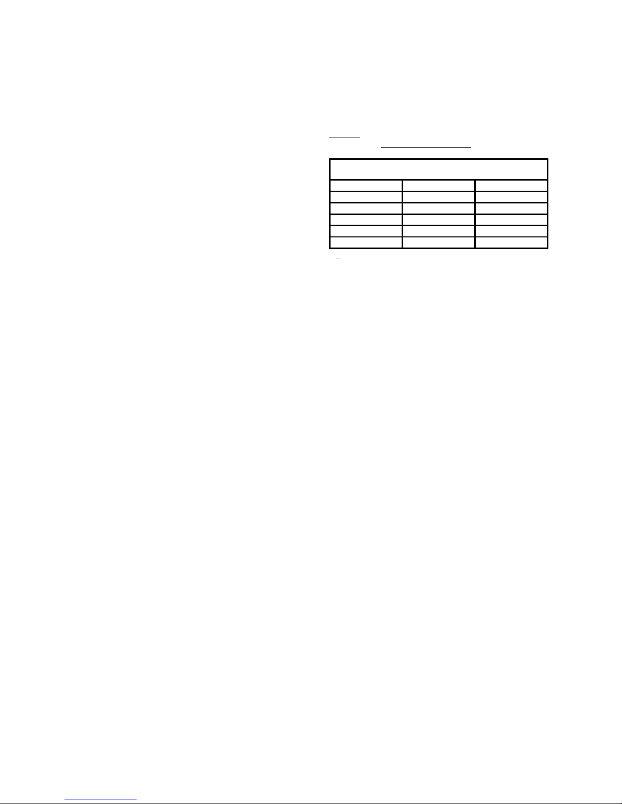
Platelet aggregation is clinically significant in the detection and
diagnosis of acquired or congenital qualitative platelet defects.
The platelet's ability or inability to respond to particular
aggregating reagents is the basis for differentiating platelet
dysfunctions6 as shown in the table below:
AGGREGATI N STUDIES N SELECTED PLATELET FUNCTI N
DEFECTS
DEFECT
Platelet
Aggregation
By ADP
Platelet
Aggregation
by Collagen
Platelet
Aggregation
by
Ristocetin
Thrombasthenia Decreased Decreased Normal
Thrombopathia or
Thrombocytopathy
Normal
(1st phase) Decreased Normal
von Willebrand's
Disease Normal Normal Abnormal
Non
-
steroidal,
Anti-inflammatory
drugs
Normal
(1st phase) Decreased Abnormal
ptical Aggregation Tests
In-vitro platelet aggregation is an effort to characterize the in-vivo
ability of the platelets to form the primary hemostatic plug.
Platelets in a suspension of plasma are isolated from an anti-
coagulated blood sample by a relatively low centrifugal force
centrifugation. This material is known as platelet rich plasma
(PRP). Platelet poor plasma (PPP) is prepared by centrifuging the
blood sample at a relatively high force.
The Born type aggregometer or optical aggregometer is a fixed
wavelength spectrophotometer with a sample chamber (or
chambers) heated to 37°C. Provision is made for stirring of the
sample because platelet to platelet contact is necessary to the
determination of in vitro platelet aggregation.
The CHRONO-LOG® sample chambers are designed so that a
beam of infra-red light shines through two cuvettes, one
containing PRP (the sample) and one containing PPP (the
reference). Silicon photodiodes detect the light able to pass
through the samples: PRP is arbitrarily considered to be 0% light
transmission or 0% aggregation; PPP is considered to be 100%
light transmission or 100% aggregation. The difference in light
transmission outputs from the photodiodes is transferred to
recording devices.
The twin well, dual infra-red beam design ensures reproducibility.
Each channel has a separate well for the test (PRP or washed
platelets; O% light transmission) and corresponding reference
(PPP or buffer; 100% light transmission) samples. A SELECT/SET
switch allows the use of either a separate or a common reference
sample. The optical aggregation output is proportional to the
continuously measured difference in light transmission between
the test and reference samples. Pressing a single pushbutton sets
the 0% and 100% light transmission baselines. With the sensitivity
of the twin-well dual-beam detection system, a count difference
of only 75 x 109/L between the test and reference sample is

Document # 49044IM1
Revision 7.5 5
Dated February 16, 017
needed for testing. If the light transmission difference between
the test and reference samples is insufficient for accurate testing,
the aggregation output cycles continuously between the baselines
to warn the operator and a Range Error will be indicated on the
front panel.
When a stimulus is added to the cuvette containing PRP and the
platelets respond, changes in light transmission occur and are
recorded over time by the recording device.
PRP, which is turbid, is stirred in a test cuvette maintained at
37° C. The light transmittance through this turbid sample is
measured relative to the PPP blank. When the agonist is added,
the platelets will form increasingly larger aggregates and the PRP
will begin to clear, allowing more light to pass through. This
increase in light transmittance is directly proportional to the
amount of aggregation and is amplified and recorded as a signal
on chart paper or digitized into a computer using AGGRO/LINK®
Opti8TM Software.
When the platelets undergo shape change in response to a
stimulus (agonist; aggregating agent), their larger size allows less
light to pass through the PRP: this is recorded as less light
transmission through the sample relative to the PPP. If the dose
of aggregating agent is strong enough to cause the platelets to
adhere to each other and form aggregates, more light is able to
pass through the PRP sample. The change in light transmission
recorded, over time, shows a trend towards the platelet poor
plasma, or 100% light transmission. In-vitro aggregation
recordings are characterized by their appearances:
•shape change
•a first wave of aggregation (primary aggregation) that may
reverse and return towards the PRP baseline
•Irreversible second wave aggregation that occurs when the
platelets’ secreted granule contents become the stimulus
and cause additional aggregation.
Aggregation curves are also characterized by:
•the maximum amount of change in light transmission caused
by the agonist (percent aggregation)
•the slope, or rate of aggregation, reported in % of
aggregation per minute.
Multiple aggregating agents and concentrations are usually used
to stimulate the platelets. Different aggregating agents stimulate
different pathways of activation in the platelets: either binding
sites or metabolic pathways. Different concentrations of agonists
are used to elicit a family of curves (dose response curves).
The pattern of responses to these test panels is compared to
established normal response patterns and established abnormal
response patterns. This information is considered to relate to the
platelet function component of hemostasis.
CHR N -L G® M DEL 490 4+, 490 4+4
AGGREGATI N SYSTEM INSTRUMENT
SPECIFICATI NS
Intended Use
The CHRONO-LOG® Model 490 4+4 Aggregometer is intended for
use for in-vitro diagnostic use for measuring Platelet Aggregation
in Platelet Rich Plasma. This device is intended to be used in a
clinical laboratory environment by laboratory technicians. For use
only with light transmission aggregometry assays cleared for use
with the CHRONO-LOG® Platelet Aggregometry systems.
perating Specifications
•Display - Liquid Crystal Display (LCD) unit with a 4 character
by -line capability. The LCD displays the actual
temperature in degrees Celsius, stirring in RPM’s,
PPP/reference Select, and calibration mode and warning
messages.
•Heater Block - Electronically controlled heater block can be
set between 35.0°C and 39.0°C in 0.1°C steps. Both the
temperature setting and actual temperature of heater block
are displayed on front panel. Operation is prevented while
temperature is outside ±0. °C of the temperature setting.
•Stirrer - Nine stirring speeds from 400 RPM to 1 00 RPM in
100 RPM steps and a stirrer stopped position. The selected
stirring speed is displayed on the front panel. Stirrer speed
accuracy is better than 0.01%. There is a feature that
prevents operation if stirrer is not within ± 10 RPM of the
selected setting.
•Optical/Aggregation/Turbidometric - Automatic baseline
setting from a front panel push button with an over-range
detection to prevent operation if baseline does not set.
•Output resistance for analog output - Less than 10,000
ohms.
•Computer Interface – USB
•Power requirements - 115 or 30VAC; 50 or 60 Hz 60 watts
max. The main supply voltage fluctuations are not to exceed
10% of the nominal supply voltage.
•Fuse – For 115 VAC: 630 mA, 50V; Time lag, 5x 0mm or
equivalent; For 30 VAC: 315 mA 50V, Time Lag, 5x 0mm
or equivalent.
•For continued protection only the correct stated fuse values
may be used. Failure to use the correct value may result in a
hazard.
•DIN input connector for an eight (8) channel configuration.
Environmental Specifications
Caution – This Instrument is intended for indoor use only.
Failure to operate in a protected environment in accordance
with instructions may present a shock hazard. Use of the
instrument in a manner contrary to manufacturer guidelines
may result in protection impairment.
•Operating Temperature: 15° to 30° C (60° to 86° F)
•Storage Temperature: - 0° to 60° C (-4° to 140° F)
•Relative Humidity: 5% to 85% (Noncondensing)
•Operating Altitude: -16 to 000 M (-50 to 6,560 ft.)
•Storage Altitude: -16 to 10,600 M (-50 to 35,000 ft.)
General
•Four (4) Channels [One, 4-Channel Module] or Eight (8)
Channels [Two, 4-Channel Modules] with connecting cable
•Sample Volume - 500 µL or 50 µL [spacer not required for
micro-volume testing]
•Cuvettes - P/N 31
•Stir Bars - reusable teflon coated P/N 313, disposable P/N
311
•Incubation Wells – two ( ) wells for each channel for P/N
31 cuvettes at 36.5° ± 1.0°C.

Document # 49044IM1
Revision 7.5 6
Dated February 16, 017
•Dimensions - 14" (35.5cm) wide, 8.5" ( 1.6cm) high, 15"
(38cm) deep [per Module].
•Weight – 19.3 lbs. (8.75kg) [per Module]
•Output
1. Analog: Connectors on rear chassis marked 1, , 3 and
4 [Module 1] and 5, 6, 7 and 8 [Module ], for interface
to a strip chart recorder. Normal operating voltages
are in the Millivolt range.
. USB: Internal AGGRO/LINK interface for use with a
computer. This option includes AGGRO/LINK® Opti8TM
and vW CoFactor Opti8TM software.
3. Interconnecting: To connect two, 4-channel modules
for eight (8) channel configuration.
•Pollution Degree
•Installation Category II
•Protection Class 1
•Equipment Mobility – Desktop
•Continuous Operation - Continuous
Recommended Optional Recorder(s) - CHRONO-LOG® Model 709
Dual Pen (Quantity 4 Recorders required). Other recorders must
have 1 megohm minimum input impedance and 100 mV range.
The minimum computer requirements for the AGGRO/LINK® are
as follows:
•Windows-based PC with a Pentium/compatible processor
running at 133 MHz or higher.
•3 Meg of system memory.
•Windows 7 or later operating system.
•Super VGA or Higher Monitor (17 inch or larger).
•Screen resolution of 800x600 or better.
•Minimum Hard Disk Space required for installation: 3MB.
•Additional Hard Disk Space for storage of tests.
•Mouse or compatible pointing device.
Instrument Controls
•Power ON/OFF switch - powers instrument on and off.
•BASELINE Pushbutton(s), one per channel - zeros instrument
output when held down, allowing the recorder baseline to
be set using the Pen Recorder Zero Control. The Pen
Recorder is set on the right of the chart. Pressing and
releasing, sets optical aggregation gain.
•SELECT Pushbutton(s) – allows for toggling between the
Stirring Speed, Temperature and PPP/Reference Setting,
using the SET pushbutton switch. One SELECT and SET
pushbutton controls two channels. For example, Channel 1
and , Channels 3 and 4, Channels 5 and 6 and Channels 7
and 8 are set in pairs.
•Stirring Range: 400 to 1 00 RPM in 100 RPM increments.
•Temperature Range: 35.0°C to 39.0°C in 0.1°C increments.
•PPP/Reference Setting … each pair of channels can be set to
reference a PPP sample in the well of that channel or can be
set to reference the PPP sample in the well of Channel 1.
•SET Pushbutton(s) - sets the Stirring Speed, Temperature
and PPP/Reference depending on which feature is selected.
•Each time the SET button is pushed, the selected function is
incremented until it reaches the maximum setting.
•Calibration Switch – located on the front of the instrument
and is key-activated.
Instrument Calibration
The optical technique is calibrated automatically during the
testing procedure.
INSTALLATI N
NOTE: For a four channel instru ent, approxi ately 1.5 sq. ft.
(0.139 sq. .) 14 x 15” of bench space is required. For an eight
channel syste , approxi ately 3 sq. ft. (0.278 sq. .) of bench
space is required.
NOTE: Software packages cannot be run si ultaneously on one
Aggregation syste . Be sure to close the AGGR /LINK® pti8TM
Software prior to opening the vW CoFactor Opti8 TM Software
and vice versa.
1. Unpack the CHRONO-LOG® Aggregometer and supplies from
their shipping containers.
. Check that the items received match the Packing List.
3. Check that the Instruments were not damaged in shipping.
4. Store the reagents as specified on each label.
5. Place the Aggregometer and Computer in a clean dry area
on a bench top at a height of 8-35’’.
6. Check that the voltage select switch on the Aggregometer is
set to the proper voltage. If the voltage select switch is
changed, then the fuse also needs to be changed to
maintain protection. Plug the power cords, as appropriate,
into a 115 or 0 Volts AC filtered power strip and then plug
the power strip into a grounded power outlet.
7. Turn power ON for the Aggregometer(s).
8. Computer Connections: (See Connection Charts in Appendix
B ) If the computer was purchased through Chrono-log the
software was pre-installed, proceed to step 9.
a. Turn power ON for the computer.
b. Place the Chrono-log supplied AGGRO/LINK® Opti8TM
Software Installation CD in the drive and run the setup
file “CDM v*.*WHQL Certified” located in the folder
named USB Drivers.
c. Connect the USB cable to the Aggregometer. Windows
should complete setting up the USB drivers on the
computer.
NOTE: If the steps above are not followed in sequence, the USB
driver ay not install co pletely. This will be indicated by FTDI
or USB Serial port devices showing up in Device Manager under
the Other Devices Category. Right Clicking these and selecting
Update driver ay co plete the installation. Please consult
your IT depart ent or Chrono-log service depart ent for
assistance.
d. The AGGRO/LINK® Opti8 TM and vW CoFactor pti8 TM
Software packages are in separate folders on the CD.
Double click each Setup.exe file to start installation of
each software and follow on-screen instructions to
complete the installation.
e. It is recommended that the software be run with
desktop composition disabled (a setting in the
Windows Operating System) and as Administrator for
all Windows user accounts. Insufficient privileges may
result in run time errors. Please consult your IT staff if
technical support is required.
9. Start the AGGRO/LINK® Opti8 TM Software on the Computer.
During the software start-up, the computer will test the
communication. The Program will respond with
AGGREGOMETER READY on the lower right side of the status
bar when communication is established.
a. If communication is not established, the Program will
continue searching and respond with AGGREGOMETER
NOT CONNECTED on the lower right side of the status
bar if connection cannot be established.

Document # 49044IM1
Revision 7.5 7
Dated February 16, 017
b. Check the cable and make sure the Aggregometer has
power.
c. To retry, select “Aggregometer” from the ribbon, then
“Connect” from the dropdown menu.
d. Once AGGREGOMETER READY appears on the lower
right side of the status bar, close the AGGRO/LINK®
Opti8 TM Software.
10. Start the vW CoFactor pti8 TM Software on the Computer.
During the software start-up, the computer will test the
communication. The Program will respond with
AGGREGOMETER READY on the lower right side of the status
bar when communication is established.
a. If communication is not established, then the Program
will continue searching and respond with A/L NOT
CONNECTED on the lower right side of the status bar if
connection cannot be established.
b. Check the cable and make sure the Aggregometer has
power.
c. To retry, select “Aggregometer” from the ribbon, then
“Connect” from the dropdown menu.
d. Once AGGREGOMETER READY appears on the lower
right side of the status bar, close the vW CoFactor
Opti8TM Software.
11. The LCD display on each channel will show a temperature
reading. This reading will settle at the desired temperature
in approximately 15 minutes.
1 . The System is now installed and ready for use.
INSTRUMENT FUNCTI N VERIFICATI N
1. Temperature Check – set to 37° in all channels.
. Stirring - take a cuvette with stir bar and place in each
reaction well to observe it spinning.
3. Optical Circuit Function - insert a BLACK cuvette from P/N
3 Calibration Kit into the reaction well for PRP. Insert a
water cuvette from P/N 3 calibration kit into the reaction
well for PPP. Press and HOLD the SET BASELINE button and
observe the tracing at the 100% light transmission baseline.
Release the SET BASELINE button and observe a return to
the PRP 0% baseline.
4. Replace the BLACK cuvette with the other water cuvette
from P/N 3 calibration kit and observe the tracing near the
100% light transmission baseline.
PERATING INSTRUCTI NS
For Model 490 4+/490 4+4, install the AGGRO/LINK® Opti8TM
Software as described previously under INSTALLATION section of
this manual.
For Model 490 4+DR/490 4+4DR the software for running the
AGGRO/LINK® Opti8TM programs were installed at the factory.
Before attempting to run aggregation testing, read the Software
section on page 10 and PROCEDURE – STEPWISE on page 11 of
this manual to learn the operation of AGGRO/LINK® Opti8TM
software.
SPECIMEN C LLECTI N:
Preparation and Handling of Blood Specimens:
It is extremely important that care be taken in the collection,
handling, and preparation of the patient's blood specimen.
Warning: Patient specimens should be handled as if they contain
infectious materials, in accordance with national guidelines for
Biosafety/Hazard Group . In the United States, the universal
precautions recommended by the Department of Labor,
Occupational Safety and Health Administration apply.
(Occupational Exposure to Blood Borne Pathogens; final rule ( 9
CFR 1910, 1030) FEDERAL REGISTER.
Essential precautions can be summarized as follows:
•Do not pipette by mouth.
•Wear disposable gloves during all specimen and assay
manipulations.
•Avoid use of sharp-pointed or glass liquid handling devices,
which may puncture skin.
•Do not smoke, eat, or drink in the laboratory area.
•Avoid splashing any liquid specimens and reagents and the
formation of aerosols.
•Wash hands thoroughly on completion of a manipulation.
Patient Preparation:
Subjects for Optical platelet aggregation tests should be resting,
fasting and non-smoking. Subjects should avoid taking any
prescription or over-the-counter medications known to affect
platelet function for ten (10) days to two ( ) weeks prior to the
test.
A partial list of medications with known antiplatelet effects
follow: 19
•C X-1 Inhibitors (Acetylsalicylic acid)
Aspirin and all proprietary or over-the-counter (OTC)
preparations containing acetylsalicylic acid
•C X-1 and C X-2 Inhibitors (Nonsteroidal anti-
inflammatory drugs [NSAIDs])
Ibuprofen, Indomethacin, naproxen, Mefenamic acid
•C X-2 Inhibitors (Coxibs)
Celecoxib
•Inhibitors of Platelet Receptors
Abciximab (αIIbβ3), Clopidogrel (P Y1 ), Prasugral (P Y1 )
•RGD Peptomimetics
Eptifibatide, Tirofiban
•Phosphodiesterase Inhibitors
Dipyridamole, Cilostazole
•Anticoagulants
Heparin, Warfarin, Direct Thrombin Inhibitors (lepirudin,
argatroban, bivalirudin)
•Cardiovascular Agents
β-adrenergic blockers (propranolol), Vasodilators
(nitroprusside, nitroclygerin), Diuretics (furosemide),
Calcium channel blockers
•Antimicrobials
β-lactams (penicillin, cephalosporins), Amphotericin
(antifungal), Hydroxychloroquines (antimalarial),
Nitrofurantoin
•Chemotherapeutics Agents
Asparaginase, Plicamycin, Vincristine
•Psychotropics and Anesthetics
Thricyclic antidepressents (imipramine), Phenothiazines
(chlorpromazine), Local and general anesthesia (fluothane)
•Miscellaneous Agents
Clofibrate, Dextrans, Guaifenesin (expectorant),
Radiographic contrast
•Foods/Herbals
Alcohol, Caffeine (methylxanthine), Garlic, Onion, Ginger,
Fish Oil, Vitamins C and E.

Document # 49044IM1
Revision 7.5 8
Dated February 16, 017
Type:
For testing with 500 µL PRP samples: Five (5) 4.5 mL blue top
evacuated tubes per patient. For testing with 50 µL PRP Samples:
Three (3) 4.5 mL blue top evacuated tubes per patient.
Specimen should be drawn with a minimum of trauma or stasis at
the venipuncture site and anti-coagulated with 3. % or 3.8%
sodium citrate, in the ratio of one (1) part anticoagulant to nine
(9) parts of blood.
An EDTA blood specimen must be collected from the patient for
hematocrit and platelet count. The blood specimen must be
collected using plastic equipment throughout.
Plastic or non-contact surfaced (siliconized) materials should be
used throughout in order to minimize activation of the platelets
during sample preparation.
Handling Conditions:
Testing can start 30 minutes after venipuncture and continue for
about .5 hours after. Specimen should be kept at room
temperature ( 4° to 7°C).
EQUIPMENT AND MATERIALS:
Equipment:
1. CHRONO-LOG® 490 4+ or 490 4+4 Aggregation system with
internal AGGGRO/LINK® Interface.
. Windows®-Compatible Computer and AGGRO/LINK® Opti8TM
software installed.
Materials:
1. P/N 31 Cuvettes
. P/N 311 Disposable Siliconized Stir bars
3. P/N 3 Calibration Kit containing 1 Black Cuvette and
Sealed Water Cuvettes.
4. P/N 331 .5-10 µL Adjustable Pipette
5. P/N 335 Tips for P/N 331
6. P/N 33 10-100 µL Adjustable Pipette
7. P/N 337 Tips for P/N 33
8. P/N 333 100-1000 µL Adjustable Pipette
9. P/N 339 Tips for P/N 333
10. P/N 384 CHRONO-PAR® ADP
11. P/N 385 CHRONO-PAR® Collagen
1 . P/N 390 CHRONO-PAR® Arachidonic Acid
13. P/N 393 CHRONO-PAR® Epinephrine
14. P/N 396 CHRONO-PAR® Ristocetin
15. P/N 397 Saline (0.9%) 15mL
Avoid blood bank saline because it ay be an incorrect
os olality. Cell counter diluents are not suitable because they
contain EDTA, which inhibits platelet aggregation. So e
infusion salines are inappropriate because they contain benzyl
alcohol (or other preservatives). Such preservatives/additives
inhibit platelet function.
16. P/N 398 Purified Water 15mL.
Should be pyrogen free (ATP free) for reconstituting reagents.
Avoid any sterile water for injection that contains benzyl alcohol
or other preservatives/additives because they inhibit platelet
function.
17. 15 mL conical test tube and cap, or similar (per test subject):
for storing the PRP and PPP specimens.
18. Ice bucket: for maintenance of the reagents during the
course of the working day
19. Vortex-type mixer: for mixing the Arachidonic Acid
0. Long-stemmed plastic transfer pipettes to take off PRP and
PPP for placing into 15 mL test tubes.
1. Lintless wipes, such as KimWipes .
Gauze squares are NOT suitable.
PREPARATI N:
1. Aggregometer
a. Turn on the unit and let it heat up for 10-15 minutes or
until the heater block stabilizes at 37°C.
b. Place P/N 311 Stir bars in P/N 31 Cuvettes.
c. Put cuvettes containing stir bar in the incubation wells
to warm up.
d. When the Model 490 4+4 test channels are set to
Reference Channel 1, a single sample of PPP can be
used as the reference sample for all tests run with the
same patient's blood, so the amount of PPP required is
only enough for one sample, about 500 µL.
2. Preparation of Sample:
a. Mix sample by gentle inversion; DO NOT SHAKE.
b. To prepare the platelet rich plasma (PRP):
1) Centrifuge sample at approximately 100-170g for
15 minutes.
) Take off the PRP with a polypropylene transfer
pipette and place into a polypropylene plastic
tube and add cap.
3) Recap the blue top tubes.
NOTE: Per CLSI Docu ent H58-A, the pH of the PRP sa ple can
be preserved as follows:19
•Place PRP in a plastic tube with li ited surface area-to-
volu e ratio (place large volu e of PRP in a s all tube)
•Cap the PRP tube as PRP in uncapped tube undergoes a rise
in pH due to diffusion of CO2 fro plas a
•Avoid frequent ixing/agitation of PRP
•Introduce PRP directly into the tube and don’t allow it to
flow down the sides of the tube.
4) Properly label the tube, include the patient's
name and sample type. Parafilm or cap the top.
Keep at room temperature ( 4°C to 7°C).
c. To prepare the platelet poor plasma (PPP):
1) Place blue top tubes into centrifuge.
) Centrifuge sample at approximately 1500- 400 g
for 0 minutes.
3) Take off the PRP with a polypropylene transfer
pipette and put it into a polypropylene plastic
tube.
4) Properly label the tube, include the patient's
name and sample type. Parafilm or cap the top.
Keep at room temperature ( 4°C to 7°C).
When ready to begin testing, dispense one aliquot per channel of
adjusted or non-adjusted PRP of 500 µL volume into P/N 31
cuvettes with stir bars. Warm for a minimum of 3 minutes. It is
not recommended to incubate a sample beyond 30 minutes.
3. Reagent Preparation
The following reagents are sourced from:
Chrono-log Corp.
W. Park Road
Havertown, PA 19083 USA
Tel: 610-853-1130

Document # 49044IM1
Revision 7.5 9
Dated February 16, 017
a. Water
Catalog No.: 398
Supplied As: Purified Water 15mL
Sterile distilled, bottled water suitable for CHRONO-
PAR® Reagent preparation.
Pyrogen free (ATP free) for reconstituting reagents
and not containing preservatives/additives such as
benzyl alcohol which inhibits platelet function. Do not
use water fro the lab purification syste .
b. Saline
Catalog No.: 397
Supplied As: Saline (0.9%) 15mL
Sterile, physiological, saline for CHRONO-PAR® Reagent
preparation.
Avoid blood bank saline because it ay be an
incorrect os olarity. Cell counter diluents are not
suitable because they contain EDTA, which inhibits
platelet aggregation. Infusion salines are
inappropriate because they contain benzyl alcohol (or
other preservatives). Such preservatives/additives
inhibit platelet function.
c. ADP
Catalog No.: 384
Supplied As: .5 mg of lyophilized preparation of
adenosine diphosphate.
Stock Conc.: 1 mM
Stock Storage: Store frozen at below 0°C
Stock Shelf life: Until expiration date.
Working Conc.: 1 mM
Working Storage: -8°C
Working Shelf life: 8 hours
Reconstitute with 5.0 mL of irrigation grade
physiological saline.
Preparation: Tap vial gently to get contents to the
bottom. Reconstitute with 5 mL of irrigation grade
physiological saline. Allow to sit for 10 minutes with
occasional inversion. Add 5 µL of reagent to 500 µL
sample or .5 µL of reagent to 50 µL sample for a final
concentration of 10 µM. Normal aggregation is seen in
PRP with final concentrations of 5-10 µM.
Stability: The reconstituted ADP reagent can be stored
frozen at -70°C volumes suitable for a days testing for
one year or until expiration date, whichever comes
first.
d. Arachidonic Acid
Catalog No.: 390
Supplied As: Minimum of 10 mg of Arachidonic Acid
with a purity of better than 99%. Albumin contains
100mg of bovine albumin, fraction V powder, 96 to 99%
pure.
Stock Conc.: 50 mM
Stock Storage: Frozen below - 0°C for Arachidonic Acid,
Refrigerate at -8°C for albumin.
Stock Shelf Life: Until expiration date.
Working Conc.: 50 mM
Working Storage: -8°C [in the dark]
Working Shelf Life: 8 hours
Reconstitute with 0.7 mL of the saline-albumin
solution.
Preparation: First tap contents gently to the bottom of
the vial of albumin. Reconstitute the albumin with 1
mL of irrigation grade physiological saline. Allow to sit,
then mix with occasional swirling. Allow 15 to 30
minutes for the albumin to fully absorb the saline
(check visually). The Arachidonic Acid in the vial is an
oily drop which must be shaken or tapped to the
bottom of the vial. Break vial tip with Cap CrackerTM
supplied. Pipette reconstituted albumin into both the
tip and body of the vial in 100 µL aliquots to a total
volume of 700 µL. Make sure any Arachidonic Acid
remaining on the tip or body of the vial is mixed by
rotating the vial as the albumin is added. Repeat a few
times in each section of the vial then vigorously mix
the Arachidonic Acid into the albumin using a transfer
pipette. Combine the suspension from the tip with
that in the body of the vial and continue mixing until
the Arachidonic Acid suspension reaches maximum
turbidity. Transfer reagent to micro centrifuge tube
and vortex for 5 minutes. The reconstituted
Arachidonic Acid suspension should appear very milky
with numerous small bubbles.
Add 5 µL of reagent to 500 µL PRP sample or .5 µL of
reagent to 50 µL sample for a concentration of 0.5
mM. Normal aggregation is seen with final
concentrations of 0.5 -1.0 mM.
Stability: The reconstituted Arachidonic Acid can be
stored frozen at -70°C in the dark in 100 µL volumes
for 3 months or until expiration date, whichever comes
first. When stored frozen at - 0°C in the dark
Arachidonic Acid is stable for 1 month or until
expiration date, whichever comes first. Aliquots can be
hand thawed and vigorously re-suspended with a
vortex mixer just before use.
e. Collagen
Catalog no.: 385
Supplied as: 1 mg of native Collagen fibrils (type I) from
equine tendons suspended in isotonic glucose solution
of ph .7/vial.
Stock Conc.: 1 mg/mL
Stock Storage: Refrigerate at -8°C
Stock Shelf Life: Until expiration date.
Working Conc.: 1 mg/mL
Working Storage: -8°C
Working Shelf life: Until expiration date.
Preparation: Collagen can be used directly as supplied.
Invert or swirl vial before use, as Collagen fibrils are in
suspension. Do not freeze. If required, Collagen can

Document # 49044IM1
Revision 7.5 10
Dated February 16, 017
be further diluted in isotonic glucose pH .7. Do not
dilute entire bottle, only enough for a day’s testing.
Add 1 µL of reagent to 500 µL sample or 0.5 µL of
reagent to 50 µL sample for a final concentration of
µg/mL. Normal aggregation is seen with final
concentrations of 1-5 µg/mL.
Stability: Collagen does not contain any preservative,
but because of its very low pH, organisms do not grow
as readily. If asceptic techniques are used (sterile
syringe and needle to remove one day’s use),
remaining reagent, if stored at - 8°C, is stable until
expiration date. Reagent removed from the vial is
stable for one week at -8°C.
f. Epinephrine
Catalog No.: 393
Supplied As: Lyophilized preparation of l-Epinephrine
bitartarate with stabilizers
Stock Conc.: 10 mM for Whole Blood Testing; 1mM for
PRP testing
Stock Storage: Refrigerate at -8°C
Stock Shelf life: Until expiration date
Working Conc.: 1 mM for PRP testing
Working Storage: -8°C in dark container
Working Shelf life: 8 hours (in the dark)
Reconstitute with 5.0 mL sterile distilled water (dilute
1:10 with physiological saline for PRP testing).
Preparation: Tap vial gently to get contents to the
bottom. Remove stopper and reconstitute with 5.0 mL
sterile, distilled water. Dilute the stock 1:10 with
physiological saline for PRP testing. Allow to sit for ten
minutes with occasional inversion. Adding 5µL of 1:10
Diluted Solution to 500 µL sample of platelet rich
plasma or .5 µL of reagent to 50 µL sample gives a
final concentration of 10 µM. Normal aggregation is
seen with final concentrations of 5-10 µM in platelet
rich plasma.
Stability: Epinephrine is a comparatively unstable
reagent. The unused reconstituted Epinephrine can be
stored frozen at -70°C in the dark and in 100 µL
aliquots for 3 months or until the expiration date,
whichever comes first.
NOTE: Nor al subjects exhibit considerable variability that is
not correlated with age, sex, stress, diet, platelet count or
he atocrit.
g. Ristocetin
Catalog No.: 396
Supplied As: 6 .5 mg of stabilized freeze dried
Ristocetin.
Stock Conc.: 1 5 mg/mL
Stock Storage: Refrigerate at -8°C (in the dark)
Stock Shelf Life: Until expiration date
Working Conc.: 1 5 mg/mL
Working Storage: -8°C
Working Shelf Life: 8 hours (in the dark)
Reconstitute with 0.5 mL of sterile distilled water.
Preparation: Tap vial gently to get contents to the
bottom. Remove stopper and reconstitute with 0.5 mL
of sterile distilled water. Do not shake or invert vial.
Re-stopper and allow to sit for 10-15 minutes. Visually
inspect bottom of vial to confirm reagent is fully in
suspension. Do not shake the reagent, invert gently, to
take up any reagent remaining in stopper and allow
vial to sit for another 10-15 minutes until all particulate
matter is well dissolved. Reagent may have a clear-to-
brownish color suspension after reconstitution. Never
shake reagent. Swirl gently just before use.
Add 5 µL of reagent to 500 µL PRP sample or .5 µL of
reagent to 50 µL sample for a concentration of 1. 5
mg/mL. Normal aggregation is seen with final
concentration of 0.63 - 1.5 mg/mL.
Stability: The unused reconstituted Ristocetin reagent
can be stored frozen at - 0°C in volumes suitable for a
days testing for 3 months or until the expiration date,
whichever comes first. DO NOT STORE AT -70oC.
4. AGGR /LINK® pti8TM Software
a. Turn on Computer and Start AGGRO/LINK® Opti8TM for
Windows® program. Be sure “Aggregometer Ready”
appears in the bottom right-hand corner of the screen.
If not, check USB Port, cables and connectors. If
USB/Com Port is changed, go to AGGREGOMETER then
CONNECT.
b. Click on EDIT and CONFIGURATION. Type in your
institutions information under Report Header. This will
be printed out on top of Report Format when Report
Batch Print is selected under File. Click on OK when
completed.
c. To have Area Under Curve and Lag Time Calculated
and printed on test data, click on the box to select. To
disable, leave this box unchecked.
d. To display and print Start Indicators, click on the box to
select. To disable, leave this box unchecked.
e. Under the AGGREGOMETER window, select or set-up a
test Procedure page for Optical mode. To save the
procedure for future use, change the name in the
Procedure Name field. Click on OK and select Run New
Patient under AGGREGOMETER.
N TE – AGGR /LINK® pti8TM Software features:
•CREATE MERGE – Creates a blank document for pasting
curves
•EXP RT - Export test data for use with another program
•ADJUST SL PE LINE – Change slope calculation time
•FFSET CURVES – Change the physical start time of a test
Channel
•C PY SCREEN – Copies the test grid and curves to the
system Clipboard
•MERGE C PY ALL or SELECTED - To copy all the curves from
a file or to copy only selected curves from a file to a merge
document.
•START & ST P TIMES – Automatic marking at addition of
reagent.
•CUST M C L R SETUP – Use Default tracing colors or
customize

Document # 49044IM1
Revision 7.5 11
Dated February 16, 017
•ACTIVATE Bar – provides the ability to control each test
individually or in sets of 2 or 4 channels, eliminating the
risk of some samples sitting in test well for extended
period of time before tests are started.
1. To run up to Eight (8) tests at the same time:
a. After a 3-minute incubation, place test cuvettes
in PRP test wells – from 1 to 8 channels
b. Click on “Activate” Bar and press the Set Baseline
button for each channel.
c. Monitor all tracings for stability.
d. Once tracings are stable and, if a clean test
screen is needed, Click on “Aggregometer” and
“Reset” for all channels.
e. If required that the Baseline setting appear on
test printout, press Set Baseline for all channels.
f. Click on “Start” Bar for Channel 1 and add
reagent.
g. If Baseline setting not required on test printout,
Click on the “Start” Bar for Channel 1 and add
reagent.
h. Repeat “e and f” or “g” for remaining channels.
. To run tests in 4 channel sets:
a. After a 3-minute incubation, place 4 test
cuvette(s) in PRP test well(s) in Channels 1 thru 4.
b. Click on “Activate” Bar and press the Set Baseline
for Channels 1 thru 4.
c. Monitor tracings for stability. [N TE: At this
point, place 4 additional test cuvettes in
Incubation wells for Channels 5 thru 8 for a 3-
minute incubation.]
d. Once tracings are stable and, if a clean test
screen is needed, Click on “Aggregometer” and
“Reset” for Channels 1 thru 4.
e. If required that the Baseline setting appear on
test printout, press Set Baseline for Channels 1
thru 4.
f. Click on “Start” Bar for Channel 1 and add
reagent.
g. If Baseline setting not required on test printout,
Click on the “Start” bar for Channel 1 and add
reagent.
h. Repeat “e and f” or “g” for remaining channels.
i. After 3-incubation, place 4 test cuvette(s) in PRP
test well(s) in Channels 5 thru 8.
j. Repeat “b” thru “h” for Channels 5 thru 8.
5. Micro-Pipettes with 2-Stop Control Button
a. Description of 2 Stops
1) First Stop – The measuring stroke for aspirating
and dispensing the selected volume
) Second Stop – To blow out any liquid remaining
in the pipette tip after dispensing.
b. Volume Setting
When adjusting the volume setting from a higher value
to a lower value, turn the knob past the desired
volume and then back to the required setting.
c. Filling the Pipette Tip
1) Press the control button down to the first stop
) Immerse the pipette tip vertically into the liquid
3) Aspirate and dispense the liquid three times by
using the first stop only.
4) Remove the tip slowly from the liquid. For large
volumes, wait approximately 3 seconds before
removing the tip from the liquid.
5) Wipe off the outside of the tip with a lint-free
tissue to remove any excess liquid, taking
precaution that the tissue does not touch the tip
opening.
NOTE: When pipetting Whole Blood, PRP or Platelets do NOT
aspirate/dispense 3 ti es. Only take up the sa ple one ti e.
d. Dispensing
Place the pipette tip into the cuvette, so that the end
of the tip is immersed in the sample.
1) Slightly angle the pipette so that the tip is angled
to touch the wall of the cuvette.
) Press the control button down to the first stop,
then press the control button down to the
second stop (blow-out) to empty the pipette tip.
3) Hold the control button down at the second
stop and, while keeping the pipette tip at a slight
angle, pull the pipette tip out of the sample.
4) Once the pipette tip is completely outside of
the cuvette, release the control button.
CALIBRATI N:
For testing platelets, the Optical mode is calibrated automatically
during the testing procedure by the setting of 0% (PRP) and 100%
(PPP) baselines.
QUALITY C NTR L:
It is good laboratory practice to run a drug free normal control
whenever reagents are reconstituted or thawed. Test results
should fall within Normal Ranges established in each laboratory.
If desired, positive controls can be provided by collecting samples
from aspirin volunteers or subjects previously diagnosed with a
platelet disorder.
Positive controls can also be made in-vitro by the addition of
aspirin or the depletion of plasma. A final concentration of 1 mM
aspirin in citrated blood will inhibit the response to arachidonic
acid. Centrifugation, removal of platelet poor plasma and
replacement with an equal volume of saline, while leaving the
buffy coat in place will inhibit response to Ristocetin.
PR CEDURE - STEPWISE:
1. Check Aggregometer to be sure heater block has stabilized
to 37°C.
. Place P/N 311 Stir bars in P/N 31 Cuvettes. Put cuvettes
containing stir bar in the incubation wells to warm up.
3. For testing the same donor in all channels, set all channels to
reference channel #1 PPP. [If each channel is set to its own
PPP, a cuvette with 500 µL PPP is required for each channel.]
SELECT Pushbutton(s) – allows for toggling between the Stirring
Speed, Temperature and PPP/Reference Settings.
SET Pushbutton(s) - sets the Stirring Speed, Temperature and
PPP/Reference, depending on which feature is selected. Each
time the SET button is pushed, the selected function is
incremented until it reaches the maximum setting.

Document # 49044IM1
Revision 7.5 1
Dated February 16, 017
N TE: ne SELECT and SET pushbutton controls two channels in
tandem. For example, Channels 1 & 2, Channels 3 & 4, Channels
5 & 6 and Channels 7 & 8 are set in pairs.
4. Place the cuvettes containing 500 µL PPP in the reference
well(s) …stir bar is not required. Check for bubbles and be
sure to wipe cuvette with a clean KimWipe.
5. Place 500 µL or 50 µL Platelet-RICH-Plasma (PRP) into pre-
warmed cuvettes with stir bars. [Prepare (1) for each test
channel.] Incubate for three (3) minutes in incubation wells
6. Start AGGRO/LINK® Opti8TM for Windows® program and
select TEST PROCEDURE under the AGGREGOMETER
window. Under PROCEDURE NAME, set-up or load the
procedure that corresponds to the reagent and method
being used. Optical tests with PRP should run for a
ini u of 5 inutes. Slope length can be set from 16 to
99 seconds. Chrono-log standard setting is 16 seconds. Click
OK.
7. Select “RUN NEW TEST” under AGGREGOMETER window.
Patient information page will appear. Patient information
can be completed at this time or can be entered during or
after test is completed. [Click on EDIT then TEST
INFORMATION] When “Run Sa e Test” is selected, patient
data fro previous test will be used.
NOTE – Patient data fro Trace 1 can be copied to other
tracings. Click on Select All if testing sa e donor in all channels
or Click on appropriate Trace Nos. and then Click on COPY.
NOTE – The Test Identification field at the top of the page is used
to identify and select test(s) in the Test Directory. For Clinical
testing, place patient identifier in this field.
8. Place the cuvettes containing PRP in the PRP wells (One for
each Optical Channel). Check for bubbles and be sure to
wipe cuvette with a clean.
9. Click OK to begin test. Click on color-coded “Activate” bar for
each channel.
10. Push the SET BASELINE buttons for each channel. The
tracing should move to 100% when the button is depressed
and to 0% when the button is released, using the numbers
on the left side of the graph. Be sure to press and hold the
Baseline button until the tracing reaches 100% of the graph
and then release.
NOTE: The Graph Range ti e can be adjusted under VIEW and
then Set Graph Range. When the test tracings have reached the
end of the Graph Range, additional ti e is added auto atically
in one inute incre ents, up to a total of 60 inutes.
11. Monitor tracings for stability.
1 . When tracing(s) have reached stability, take up the
appropriate reagent and click on the color-coded “Start” bar
for Channel 1. [ r … See N TE 2 below].
13. Add reagent
a. Use 1 µ
µµ
µL of Collagen with 500 µL sample volume or
0.5 µ
µµ
µL with 50 µL sample for 2 µ
µµ
µg/mL final
concentration…or for a 5 µ
µµ
µg/mL final concentration
use 2.5 µ
µµ
µL with 500 µL sample volume or 1.25 µ
µµ
µL with
50 µL sample.
NOTE: As shown above, reagent volu es are cut in half when
testing with 250
µ
µµ
µ
L PRP sa ples.
b. Use 5 µ
µµ
µL of ADP with 500 µL sample volume for a final
concentration of 10 µ
µµ
µM…or 2.5 µ
µµ
µL for 5 µ
µµ
µM.
c. Use 5 µ
µµ
µL of Arachidonic Acid with 500 µL sample
volume for a final concentration of 0.5 mM…or 2.5 µ
µµ
µL
for 0.25mM.
d. Use 5 µ
µµ
µL of Ristocetin with 500 µL sample volume for a
final concentration of 1.25 mg/mL.
e. Use 2 µ
µµ
µL of Ristocetin with 500 µL sample volume for a
final concentration of 0.5 mg/mL (Type B vW).
f. Use 2.5 µ
µµ
µL of Epinephrine with 500 µL sample volume
for a final concentration of 5 µ
µµ
µM.
NOTE – CHRONO-PAR® Reagents do not require preparation of
ultiple stock solutions. To change final concentration, adjust
pipette volu es as shown above.
14. Repeat steps 1 and 13 for each test channel.
15. Allow all tests to run for a minimum of five (5) minutes.
NOTE: The “Activate” bar in Step 9 provides the ability to control
each channel individually and to stagger the start of each test.
NOTE: To have the baseline setting visible on the final printout,
when a tracing has reached stability, Click on Aggrego eter …
Reset Channel … and select appropriate Channel #. Click on the
“Activate” bar and reset the baseline. Then, click on the “Start”
bar and add the appropriate reagent for that Channel.
16. While tests are running, prepare one test cuvette for each
channel (Cuvette, stir bar and 500 µL or 50 µL PRP) & begin
three (3) minute incubation.
17. There are a number of Options to Stop Tests as each test can
be stopped individually or all tests stopped at the same
time, as follows:
a. To Stop Tests individually, click on Aggregometer, click
on Stop Test and select the appropriate Channel.
b. STOP Icon at top of screen stops all tests at the same
time.
18. Clicking on the “Start” bar prior to adding the reagent sets
the Start and Stop time for each channel. If there is a
baseline shift or some other artifact that should not be
included in the final calculation, Click on EDIT and SET START
& STOP TIMES (or use ICONS at top of screen).
a. If only calculating Slope and Amplitude:
1) A small box will appear with Trace 1 selected.
) If the Automatic Start Time Feature was used
before the addition of the reagent, a dotted line
will appear on the screen at that point (Start
Line) with another dotted line (Stop Line) placed
“X” number of minutes after (Test Time set up on
procedure page).
3) If required, Start & Stop times can be moved:
a) Individually – Left Click, Hold and Drag to
new position. (Be sure Start Line is placed
on stable baseline just before or just after
adding the reagent. Stop Line should be
placed five (5) minutes after the Start
Time.)
b) Simultaneously – Place cursor near Start
Line. Right click, Hold & Drag Start Line to
new position. Stop Line will move in
tandem.
4) Click on other Tracings and repeat, if needed.
Document # 49044IM1
Revision 7.5 13
Dated February 16, 017
b. If calculating Slope, Amplitude, Lag Time and Area
Under the Curve at the same settings:
1) Click on Trace 1
) Click on “Set All” to calculate all parameters with
one setting.
3) Follow Steps ) through 4) above.
NOTE – When calculating Lag Ti e individually, only a start ti e
is displayed.
19. After setting the Start and Stop Times, Click on DONE, then
select Calculate Results under the EDIT window (or use
ICON). This command will calculate aggregation percentage,
slope and if selected, lag time and area under the curve.
Check Duration times to be sure Start & Stop Lines were set
correctly. Click on OK and calculations will appear in Data
Box.
0. After the calculations have been completed, SAVE the test,
using the SAVE command under FILE. Tests can be printed
using the PRINT command in the FILE WINDOW. PRINT is for
printing one test per page.
1. To print multiple test graphs separately at one time or in a
Report Format, click on File and Report Batch Print, followed
by:
a. Select the tests to be printed by placing (√) in boxes to
left of tests listed.
b. Click on the “Insert Selected” button to move tests to
lower panel.
c. The order the tests are printed out can be arranged by
using UP or DOWN buttons.
d. Click on “Report Print” to include all selected tests in a
single report … or,
e. Click on “Batch Print” to print each test separately.
. Remove the samples from the reaction well and discard.
CALCULATI NS:
1. Amplitude – Optical aggregation results are expressed as a
percentage of aggregation at a given time interval from
reagent addition; 100% aggregation is defined as the
difference between the 0% (PRP) baseline and the 100%
(PPP) baseline.
. Slope – Slope is determined by drawing a tangent through
the steepest part of the curve. A right triangle is then
constructed over an interval of one minute. The height of
the triangle is the rate of change of aggregation in one
minute, which is defined as the slope. AGGRO/LINK®
Opti8TM
Software can be set from 16 to 99 seconds (3 point to 198
point) sliding curve. To change the length of a slope line,
click on EDIT, then ADJUST SL PE LINE. Click on Trace
number and use arrows to adjust slope length up to 99
seconds. Chrono-log standard setting is 16 seconds (3
points).
REP RTING RESULTS:
1. Report Hematocrit.
. Report Platelet Count.
3. Report Platelet Aggregation percent and slope.
Reference Ranges:
NOTE: The following Nor al Ranges were obtained fro
various laboratories and publications. They should be used as a
guideline only. Nor al ranges should be established for
aggregation in each and every laboratory.
Normal Ranges in
Platelet Rich Plasma
(Mean ±
±±
±1 SD)
Reagent
Conc.
Agg. (%)
18
Collagen
2 µg/mL
70
–
94
Arachidonic Acid
0.5 mM
74
–
99*
13
ADP
10
µM
71
–
88
Epinephrine
5
µM
78
–
88
Ristocetin
1.25mg/mL
87
–
102
13
(*+ 2 SD)
Procedures for Abnormal Results:
1. When Normal Control Test(s) Is Abnormal
a. No patient result shall be reported if any reagent does
not recover findings within reference range limits
when tested with the normal control.
b. Repeat both Normal Control and Patient test with new
aliquot of frozen reagent or reconstitute new vial of
reagent. Be sure each test cuvette contains a stir bar.
. When Normal Control Test(s) Is Normal
a. Repeat abnormal patient test(s) to be sure result is not
due to a technical variable. Be sure each test cuvette
contains a stir bar.
b. If repeated test(s) continue to be abnormal, report the
abnormal result(s) and request a retest on another day
to confirm findings.
Platelet Abnormalities
Platelet aggregation is clinically significant in the detection and
diagnosis of acquired14 or congenital qualitative platelet defects.
The platelet’s ability or inability to respond to particular
aggregating reagents is the basis for differentiating platelet
dysfunctions as shown in the table on the following page.

Document # 49044IM1
Revision 7.5 14
Dated February 16, 017
* Second-wave Inhibited
** Type B and Platelet-type von Willebrand increased at low concentration 0. -0.6 mg/mL. In addition, when cryoprecipitate is
added to test sample from patient with Platelet-Type [pseudo] VWD, enhanced response to low concentration Ristocetin will
continue, a Type B patient will show no response.7
*** To distinguish between von Willebrand & Bernard Soulier, add normal plasma or cryoprecipitate to patient sample, vW patient
will respond, Bernard Soulier will not. 19
Key: A – Absent H – Hyper N – Normal R - Reduced
(Compared to Normal Ranges)
AGGREGATION RESPONSE WITH SELECTED ABNORMALITIES
Reagent Final
Concentration Aspirin Effect Von Willebrand &
Bernard Soulier
Storage Pool/
Secretion Defect Glanzmann's Thrombasthenia
ADP 5 – 10 µ
µµ
µM N, R * N N, R * A
Arachidonic Acid 0.5 mM A N N A
Collagen 1 – 5 µ
µµ
µg/mL
1 or 2
µ
µµ
µg/mL 5 µ
µµ
µg/mL N
N
A
R
N
Epinephrine 10 - 50 µ
µµ
µM R* N R * A
Ristocetin 0.5 – 1.5
mg/mL
Qualitative
Defect
** A,R,H ***
N N

Document # 49044IM1
Revision 7.5 15
Dated February 16, 017
Reporting Format:
PLATELET AGGREGATI N STUDIES:
DATE __________________________________
PHYSICIAN _________________________________ TIME BL D DRAWN: ___________
INSTITUTI N: ______________________________ DEPARTMENT: ____________________
PATIENT ___________________ I.D. _______________ DATE F BIRTH: ______________
AGE: ________ SEX: (M) (F) HCT ___________ PLT CT _________ BT _________
CLINICAL HIST RY: ______________________________________________________________________________________
________________________________________________________________________________________________________
________________________________________________________________________________________________________
PTICAL AGGREGATI N TEST RESULTS
AG NIST N RMAL RANGES
(Mean ±
±±
±1 SD)
C NTR L
VALUE
PATIENT
VALUE
TEST
RESULTS
(Normal, Reduced,
Increased)
ADP, 5 µ
µµ
µM
69 - 88%
ADP, 10 µ
µµ
µM
71 - 88%
C LLAGEN, 2 µ
µµ
µg/mL
70 - 94%
C LLAGEN, 5µ
µµ
µg/mL
ARACHID NIC ACID,
0.5 mM
74 - 99%*
EPINEPHRINE, 5 µ
µµ
µM
78 - 88%
RIST CETIN, 1.25 mg/mL
87 - 102%
RIST CETIN, 0.5 mg/mL
0%
* ±
±±
±2SD
INTERPRETATI N:
_____________________________________________________________________________________________________________________
_____________________________________________________________________________________________________________________
_____________________________________________________________________________________________________________________
TEST PERF RMED BY: ___________________________________ INTERPRETED BY: _______________________________________________

Document # 49044IM1
Revision 7.5 16
Dated February 16, 017
INTERPRETATI N:
Aggregation curves in PRP can be interpreted as follows:
•By direct comparison to a normal drug free control which
also provides real time quality control.
•Comparison to published normal values that can be verified
and reproduced by any laboratory.
With Collagen: Collagen is useful for checking the platelet’s
general ability to aggregate. A lag phase of up to a minute is
typically seen with this agonist.
With Arachidonic Acid: Arachidonic Acid is converted to
thromboxane A in the presence of cyclooxygenase. Aspirin
inhibits the cyclooxygenase pathway, causing a significant
reduction in aggregation with this agonist. Normal aggregation is
seen with concentrations of 0.5 mM to 1.0 mM.
With ADP: ADP exposes the fibrinogen binding site on the
membrane glycoprotein GPIIb/IIIa complex. Aggregation testing is
typically performed in PRP with concentrations ranging from 1 µM
to 10 µM. At the lower concentrations up to 3 µM, a first wave of
aggregation will be followed by disaggregation. At the higher
concentrations, the first wave of aggregation will blend into the
second wave, masking the biphasic wave. It is often necessary to
perform dose-response testing with multiple concentrations to
obtain a biphasic response. Aspirin effect may be seen with mid-
range concentrations such as 5 µM.
With Epinephrine: Shape change is not seen with this agonist.
Higher concentrations (≥ 5 µM) produce a biphasic curve with
second-wave aggregation dependent on thromboxane A
synthesis. “Epinephrine is the least consistent agonist used in the
assessment of platelet aggregation and, if the Epinephrine
response is the only abnormality seen in testing, one should be
very hesitant to make the diagnosis of a ‘disorder’ based on this
result.” 18
With Ristocetin: This antibiotic is used for the detection of von
Willebrand Disease (a quantitative or qualitative defect in plasma
vW Factor) and Bernard Soulier (a lack of platelet membrane
glycoprotein (GPIb). Normal results are seen with concentrations
ranging from 0.75 to 1.5 mg/mL. To detect Type B or Platelet-
Type vW, test for a Hyper-response at low concentrations (0. –
0.6 mg/mL). 7 To distinguish between vW and Bernard Soulier,
add normal plasma or cryoprecipitate to patient sample. vW
patient will respond, Bernard Soulier will not. A Qualitative defect
such as a saw-tooth pattern may be seen with subjects taking
aspirin.
PR CEDURE N TES:
1. With the Model 490 4+4, spacers are not required when
testing micro-volume samples ( 50 µL of PRP) and all
CHRONO-PAR® reagent volumes are reduced by half. For
example: 5 µ
µµ
µL of ADP = a final concentration of 10 µ
µµ
µM with
a 500 µ
µµ
µL PRP sample… use only 2.5 µ
µµ
µL with a 250 µ
µµ
µL PRP
sample.
. It is important that the pipette tip be pushed to the bottom
of the cuvette & the reagent forcefully injected into the
sample. D N T introduce the reagent above the sample in
the cuvette since the reagent will cling to the side of the
cuvette and will not mix with the sample. (DO NOT forcefully
inject reagent if testing with smaller volume of 50 µL PRP.)
LIMITATI NS F THE PR CEDURE:
•In a study of one hundred and six patients with storage pool
deficiency (SPD), 3% had normal optical (PRP) aggregation
responses to ADP, Epinephrine and Collagen; and 44% had
miscellaneous aggregation abnormalities. The authors
concluded that SPD is common, heterogeneous and not
necessarily associated with optical (PRP) aggregation
abnormalities. 10
•Tests should be performed within 3 hours of venipuncture.
•Many drugs inhibit platelet function. 5,11,19 Unless the aim of
testing is to demonstrate drug-induced inhibition, patients
should be drug free for ten (10) days to two ( ) weeks prior
to testing.
•Further Clinical and Laboratory evaluation may be required
to confirm diagnosis.
•Red Blood Cells in PRP can inhibit the ability of the
Aggregometer to detect changes in light intensity. This may
cause the appearance of a decrease in platelet
aggregation.19
•Hemolysis results in release of nucleotides from the red cells
which may cause activation or desensitization of platelets,
especially to ADP.19
•Lipids in PRP can interfere with light transmission readings &
prevent recording of aggregation.
•Platelet counts below 100,000/µL may cause problems with
the setting of optical baseline, preventing the recording of
aggregation
•This device has not been evaluated for pediatric use.
SERVICE/PREVENTATIVE MAINTENANCE
This Unit does not require Preventative Maintenance; however,
yearly calibration is recommended. Calibration and service, if
required, should be obtained from the factory or a factory
authorized representative.
In the 48 continental United States a Factory Service and Loaner
Contract program is available. On-site field service is also
available in some areas. Contact the factory for details.
Outside of the United States contact your distributor for service.
In countries where there is no distributor, contact Chrono-log
directly.
Replacement of Parts: Critical components should only be
replaced with manufacturer approved parts. Maintenance should
be performed according to service manuals and PM checklists.
Protective Earth Ground: The instrument is connected to ground
at the instrument chassis. This sole purpose connection point is
made between the power entry module and the chassis with
green/yellow wire and is marked with the IEC 60417-5019
symbol. This connection must be reestablished if it is
removed for any purpose during servicing.
CLEANING SYSTEM C MP NENTS
Recommended Tools and Accessories
A Liquid Dishwashing Detergent -- Use a mixture of one part liquid
dishwashing detergent and three parts water to clean the exterior
of the Aggregometer.

Document # 49044IM1
Revision 7.5 17
Dated February 16, 017
A Soft, Lint-Free Cleaning Cloth -- Moisten the cleaning cloth with
the dishwashing detergent solution to clean the exterior of the
Aggregometer.
A Small Vacuum Cleaner with a Brush attachment -- Use the
vacuum cleaner to remove dust and dirt from the exterior of the
Aggregometer.
Cleaning the Aggregometer
1. Turn off the Aggregometer and any attached peripherals.
Disconnect them from the Aggregometer. Unplug the
instrument before cleaning to prevent a shock hazard should
any fluid enter the power switch.
. Use a vacuum cleaner to remove any dust from the slots and
holes in the Aggregometer.
3. Moisten a soft cleaning cloth with a solution of three parts
water and one part liquid detergent.
N TE -- D N T S AK THE CL TH IN THE S LUTI N; D N T
LET S LUTI N DRIP INSIDE THE AGGREG METER.
4. Use the moistened cloth to wipe the Aggregometer exterior.
SELF-CALIBRATI N F PTICAL CIRCUITS
This procedure enables the Optical wells (PRP & PPP) to be
calibrated automatically with the push of a button and verifies
that the instrument's optical circuits are operating properly.
During the performance of this procedure, the light intensity of
the LEDs are adjusted and set to the proper calibrated voltage.
Use a stop watch or timer since some of the steps must be timed.
The calibration switch located on the front of the instrument is
key-activated. This is to prevent unauthorized use or accidental
initialization of the procedure. DO NOT LEAVE THE KEY IN THE
SWITCH WHEN NOT PERFORMING THE CALIBRATION
PROCEDURE. The key should be stored in a safe location
accessible only to personnel authorized by laboratory
management. If the key is lost, a replacement key may be
purchased from the factory. Please note your Key # here
____________________.
Failure to follow this procedure exactly may result in an
inaccurate calibration. The Post Calibration Test checks the
accuracy of the calibration and enables the operator to have a
record of the results. This calibration procedure is not a
substitute for the recommended yearly instrument calibration
and PM.
Preparation:
1. Materials Required
a. P/N 3 . Calibration Kit with (1) black cuvette and ( )
sealed water cuvettes.
b. Lint-Free Wipe
c. Calibration Key
. Turn on the unit and let it heat up until the heater blocks
stabilize at 37°C.
3. Since each Channel is calibrated independently, confirm
that that PPP/Reference Select Switches are set to
reference each Channel's PPP sample, and are not
referencing Channel #1 PPP.
NOTE: Additional steps required for CHRONO-LOG® instru ents
that have a PPP Reference switch allowing ultiple channels to
reference the PPP in Channel. [See “Additional Post Calibration
test for Instru ents with PPP Select Switches” on Page 19 ]
4. Place the ( ) water cuvettes from P/N 3 in the incubation
wells and pre-warm for a minimum of five (5) minutes. Be
sure to always wipe cuvettes with Kim Wipe® before placing
in test or reference wells.
5. Turn on computer and Start AGGRO/LINK® Opti8TM for
Windows® program.
6. Under the AGGREGOMETER window, select or set-up a Test
Procedure page for Optical mode. Click on OK.
7. Select RUN NEW PATIENT under AGGREGOMETER and Click
on OK.
8. Type, “Optical Calibration Pre”, in Test Identification box at
top of screen. Click on OK and test will begin running.
9. After the five (5) minute incubation, check cuvettes for air
bubbles. Eliminate bubbles by tapping the cuvette.
Pre-Calibration Test
NOTE: Throughout the entire procedure, the Water Cuvette used
in the PRP well should only be used in PRP test wells and the PPP
Water Cuvette should only be used in PPP reference wells. Be
sure to use the Align ent Mark on side of each cuvette to ensure
consistent place ent of cuvettes into test and reference wells.
1. Click on Aggregometer, select Reset Channel and select ALL
Channels. Click on OK.
. After wiping the outside with a Kim Wipe®, place BLACK
cuvette in Channel 1 PRP well and a water cuvette in the PPP
well of Channel 1, with the alignment mark placed left
center.
3. Click on the Channel 1 “Activate” bar. [NOTE: If this pre-test
is to be SAVED, Click on the “Start” Bar for Channel 1. If not
saving, the following steps can be performed after clicking
on the “Activated” button. ]
4. Push and Hold the Set Baseline button until the tracing
reaches a full 100% of graph before releasing. Tracing will
then return to 0% of graph.
5. Replace the BLACK cuvette in the PRP well with the other
water cuvette, after wiping the outside with a Kim Wipe®.
Be sure alignment mark is placed left center. The tracing
should move near 100% on the graph. Allow to run for a
few seconds and note the position where the tracing
stabilizes. (Ex: 97%)
6. Repeat Steps through 5 above for Channel , and then
continue to repeat for Channels 3, 4, 5, 6, 7 and 8. Be sure
to use the water cuvette in the PPP well in all PPP wells and
the water cuvette in the PRP well in all PRP wells. Also be
sure to wipe the outside with a Kim Wipe® and to place the
Alignment Mark to the left center of the test well.
7. If saving the test … Once all channels are completed, Click on
the STOP icon followed by the SAVE icon and the PRINT icon
to save and print the test.
8. If any tracing is > 4% from 0% or 100% on the graph,
proceed with calibration steps below, calibrating all eight (8)
channels.

Document # 49044IM1
Revision 7.5 18
Dated February 16, 017
Calibration
NOTE: Calibrate ALL test channels, even if only one channel is
out of tolerance. This will ensure that all LEDs are set to the
sa e intensity.
1. Click on Aggregometer, select Reset Channel and then select
ALL Channels. Click on OK.
. After wiping the outside with a Kim Wipe®, place BLACK
cuvette in PRP well of Channel 1 and place PPP water
cuvette in PPP well.
3. Click on the “Activate” bar for Channels 1 through 8.
4. Press the Baseline button for Channel 1 and hold until the
tracing reaches a full 100% of graph before releasing.
Tracing will then return to 0% of graph.
5. Transfer the BLACK cuvette in PRP well and water cuvette in
PPP well to Channel and repeat Step 4.
6. Repeat Step 5 for Channels 3 through 8.
7. Remove Black cuvette from test well.
8. Click on the “Start” Bar for Channels 1 through 4.
9. After wiping the outside with a Kim Wipe® and keeping the
Alignment Marks left center, place the PRP water cuvette in
Channel 1 PRP well and the “P” water cuvette in Channel 1
PPP well.
10. Place the key in the calibrate switch on the module
containing Channels 1 through 4 and turn the key clockwise
90°and keep it in this position. Since calibration does not
start until the baseline is set, all four (4) channels can be
calibrated.
11. Set the timer for one minute but do not start. Press the Set
Baseline button for Channel 1, hold for a second, then
release. Start the timer as it may take up to a minute for the
channel to calibrate. During this minute DO NOT touch or
move the samples. Moving the samples may cause
inaccuracies in the calibration. Wait for the one minute [or
when tracing runs stable for around 20 seconds] before
proceeding to the next step.
NOTE: Disregard traces during calibration.
1 . After waiting one minute, or when tracing stabilizes in
Channel 1 … Repeat steps 9 through 11 for Channel , then
3, then 4. Calibration key remains ON throughout this
process.
13. Once step 1 is completed for all four (4) channels, turn OFF
the calibration mode by turning calibrate key counter-
clockwise 90° and remove the key from the lock.
Calibration of Module 1 is now completed.
14. To calibrate Channels 5, 6, 7 and 8 in Module 2, beginning
with Channel 5, repeat steps 8 through 13above, using the
calibrate key in that odule.
15. If required, SAVE and PRINT the test.
Post Calibration test
[Confirm the Calibration Key has been removed from
lock]
1. Under the AGGREGOMETER window, select or set-up a Test
Procedure page for Optical mode. Click on OK.
. Select RUN NEW PATIENT under AGGREGOMETER and Click
on OK.
3. After wiping the outside with a Kim Wipe®, place BLACK
cuvette in Channel 1 PRP well and the PPP water cuvette in
the PPP well of Channel 1, with the alignment mark placed
left center.
4. Click on the Channel 1 “Activate” bar. [NOTE: If this test is to
be SAVED, Click on the “Start” Bar for Channel 1. If not
saving, the following steps can be performed after clicking
on the “Activate” button.]
5. Push and Hold the Set Baseline button until the tracing
reaches a full 100% of graph before releasing. Tracing will
then return to 0% of graph.
6. After wiping the outside with a Kim Wipe®, replace the
BLACK cuvette in the PRP well with the PRP water cuvette
with the alignment mark placed left center. The tracing
should move near 100% on the graph. Allow to run for a
few seconds and note the position where the tracing
stabilizes. (Ex: 97%)
7. Repeat Steps 3 through 6 for Channel , then repeat for
Channels 3, 4, 5, 6, 7 and 8. Be sure to use the PPP water
cuvette in the PPP wells and the PRP water cuvette in the
PRP wells. Also be sure to place the Alignment Mark to the
left center of each test well and to wipe the outside of the
cuvettes with a Kim Wipe® when placing into the test well.
8. If any tracing is > 4% from 0% or 100% on the graph,
calibration of that Channel will need to be repeated,
following the previous calibration steps.
9. If saving the test … Once all channels are completed, Click on
the STOP icon followed by the SAVE icon and the PRINT icon
to save and print this test.
NOTE: If the tracings are > 4% fro 0% or 100% on the graph,
this ay indicate that Auto-Calibration was not set properly.
Recheck the two water cuvettes to be sure they atch. See
Appendix A for further instructions on atching water cuvettes,
then repeat the entire calibration procedure. Be sure to wipe the
cuvettes with a Ki Wipe® each ti e they are placed into a test
or reference well. If, after the second atte pt, the results are
> 4%, the syste ay need Service. Contact Chrono-log Service
Depart ent at 1-800-247-6665 for further assistance.
Additional Post Calibration test for Instruments
with PPP Select Switches - This section provides for the
ability to check each channel’s calibration against the Channel 1
PPP Reference.
[Confirm the Calibration Key has been removed from
lock]
SELECT Pushbutton(s) – allows for toggling between the Stirring
Speed, Te perature and PPP/Reference Settings.
SET Pushbutton(s) - sets the Stirring Speed, Te perature and
PPP/Reference, depending on which feature is selected. Each
ti e the SET button is pushed, the selected function is
incre ented until it reaches the axi u setting.
NOTE: One SELECT and SET pushbutton controls two channels in
tande . For exa ple, Channels 1 & 2, Channels 3 &4, Channels 5
& 6 and Channels 7 & 8 are set in pairs.
1. Set all Channels to Reference Channel 1 PPP
a. Push SELECT pushbutton for Channels 1 and until
PPP/Reference setting is displayed on the LCD screen.
b. Push SET pushbutton for Channels 1 and until the
reference to Channel 1 PPP is displayed.

Document # 49044IM1
Revision 7.5 19
Dated February 16, 017
c. Push SELECT pushbutton for Channels 1 and to return
to Default screen … which will inactivate the SET
pushbutton for those two channels.
d. Repeat steps a through c for remaining channels.
. Under the AGGREGOMETER window, select or set-up a Test
Procedure page for Optical mode. Click on OK.
3. Select RUN NEW PATIENT under AGGREGOMETER and Click
on OK.
4. After wiping the outside with a Kim Wipe® , place BLACK
cuvette in Channel 1 PRP well and the PPP water cuvette in
the PPP well of Channel 1, with the alignment mark placed
left center.
5. Click on the Channel 1 “Activate” bar. [NOTE: If this test is to
be SAVED, Click on the “Start” Bar for Channel 1. If not
saving, the following steps can be performed after clicking
on the “Activate” button.]
6. Push and Hold the Set Baseline button until the tracing
reaches a full 100% of graph before releasing. Tracing will
then return to 0% of graph.
7. After wiping the outside with a Kim Wipe®, replace the
BLACK cuvette in the PRP well with the PRP water cuvette.
The tracing should move near 100% on the graph. Allow to
run for a few seconds and note the position where the
tracing stabilizes. (Ex: 97%).
8. Repeat Steps 4 through 7 for remaining channels, except …
leave the PPP cuvette in the Channel 1 PPP well. Also be
sure to place the Alignment Mark to the left center in each
test well and to wipe the outside of the cuvettes with a Kim
Wipe® when placing into the test well.
9. If any tracing is > 4% from 0% or 100% on the graph,
calibration of that Channel will need to be repeated,
following the previous calibration steps.
10. If saving the test … Once all channels are completed, Click on
the STOP icon followed by the SAVE icon and the PRINT icon
to save and print this test.
NOTE: If the tracings are > 4% fro 0% or 100% on the graph,
this ay indicate that Auto-Calibration was not set properly.
Recheck the two water cuvettes to be sure they atch. See
Appendix A for further instructions on atching water cuvettes,
then repeat the entire calibration procedure. Be sure to wipe the
cuvettes with a Ki Wipe® each ti e they are placed into a test
or reference well. If, after the second atte pt, the results are
still > 4%, the syste ay need service. Contact Chrono-log
Service Depart ent at 1-800-247-6665 for further assistance.
Discussion
The Black cuvette blocks all light from passing through. The clear
water samples allow the maximum amount of light through. Each
instrument is adjusted at the factory for a set voltage with water
samples. The automatic calibration procedure resets the voltage
while the water samples are in the wells.
The water samples have equal optical density and should allow
the same amount of light to pass through the samples. This will
result in a tracing at 100% of the test graph. This tracing is used
to check that the calibration is set properly.
Sometimes the difference is caused by variations in the cuvettes.
If the baseline is not within 4% of the 100% baseline, the P/N 3
Kit may need to be replaced.
The PRE-calibration, Calibration and POST- Calibration steps
described above will catch calibration errors, including conditions
where one channel has matching wells that do not match the
remaining channels. Calibration with empty wells is one instance
that would create this problem. Faults may occur at any time due
to spills, broken glass, etc. Daily Quality Control checks can be
performed to prevent false readings.
If the tracing is still > 4% after following this procedure, contact
Chrono-log Service Department at 1-800- 47-6665 to inquire
about instrument service.
Troubleshooting Guide
Many factors will affect the performance and reproducibility of
test runs on the Aggregometer. These can be broken down into
several categories; Instrument failure or Calibration problems,
Sample and Materials problems, and Operator technique related
problems. Below is a brief list of common problems.
Missing stir bar
Bubbles in sample blocking optical path
Sample volume too low
Platelet count- PRP below 75K, PPP above 3K
Platelet count- mismatch between PPP samples for each
Cuvette dirty, scratched
Stirring RPM setting mismatch
Stirring motor failure
Inconsistent pipetting; force, position, tip too short.
ROUTINE QC CHECKS should be performed on a quarterly basis, or
if any of the following conditions should exist during testing.
Optical calibration should be checked with Water Samples as
described under the Pre-Calibration procedure. If required,
Calibration of the Optical Circuits can be performed using the
same Water Samples as described under Calibration.
Test Results > 100%
Test Results on all channels do not fall within +/- 10% of the
average
If these suggestions do not solve the problem, then contact
Chrono-log or your local distributor to inquire about service.
Assistance and Distributor Information
For Assistance on training, service, software updates and other
information, contact your Chrono-log representative or your local
distributor. Information on Chrono-log Distributors can be found
on the Chrono-log website at www.chronolog.com.
Table of contents
Popular Measuring Instrument manuals by other brands

TRAMEX
TRAMEX MRH III instruction manual

EUTECH INSTRUMENTS
EUTECH INSTRUMENTS CYBERSCAN PC 510 PHCONDUCTIVITY METER instruction manual

Flexim
Flexim FLUXUS F401 user manual

Precision Digital Corporation
Precision Digital Corporation PD6900 Series instruction manual

PCB Piezotronics
PCB Piezotronics 037P100 Installation and operating manual

Lika
Lika CB59 user manual


