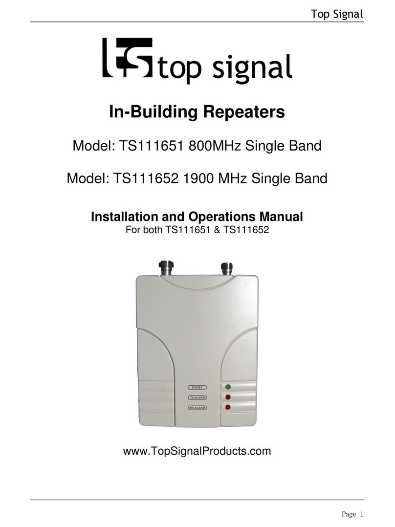
CI Wireless MirrorCell Select User manual

Operator's Manual
MirrorCell Select
CDMA Repeater
Model CDR812
Model CDR801
1211 Ira E. Woods avenue
Grapevine, TX 76051
(817) 416-0583
Fax: (817) 488-1949

Introduction CI Wireless Inc.
MirrorCell Select CDR812 Manual
ii Rev. X1
File: \CDR812X1.DOC
Rev. X1
07 SEPT 1999

CI Wireless Inc. Introduction
MirrorCell Select CDR812 Manual
Rev. X1 iii
Disclaimer
Every attempt has been made to make this material complete, accurate, and up-to-date. Users are
cautioned, however, that CI Wireless Inc. reserves the right to make changes without notice and
shall not be responsible for any damages, including consequential, caused by reliance on the
material presented, including, but not limited to, typographical, arithmetical, or listing errors.
Copyright Information
© 1999by CI Wireless Inc.
CI Wireless Inc.
Grapevine, TX 76051

Introduction CI Wireless Inc.
MirrorCell Select CDR812 Manual
iv Rev. X1
WARNINGS, CAUTIONS, AND GENERAL NOTES
This product conforms to FCC Part 15, Section 21. Changes or modifications not expressly
approved by the party responsible for compliance could void the user's authority to operate
the equipment.
Note: This equipment has been tested and found to comply with the limits for a Class A
digital device, pursuant to part 15 of the FCC rules. These limits are designed to
provide reasonable protection against harmful interference when the equipment is
operated in a commercial environment. This equipment generates, uses and can
radiate radio frequency energy and, if not installed and used in accordance with the
instruction manual, may cause harmful interference to radio communications.
Operation of this equipment in a residential area is likely to cause harmful
interference in which case the user will be required to correct the interference at
their own expense.
Safety Considerations
When installing or using this product, observe all safety precautions during handling and
operation. Failure to comply with the following general safety precautions and with specific
precautions described elsewhere in this manual violates the safety standards of the design,
manufacture, and intended use of this product. CI Wireless Inc. assumes no liability for the
customer's failure to comply with these precautions.
WARNING
WARNING Calls attention to a procedure or practice which, if ignored, may result in damage
to the system or system component. Do not perform any procedure preceded by a WARNING until
described conditions are fully understood and met.
If You Need Help
If you need additional copies of this manual, or have questions about system options, or
need help with installation and using of the system, please contact CI Wireless’Sales
Department.
CI Wireless Sales Dept.
1211 Ira E. Woods Ave. Grapevine, TX 76051 USA
(817) 416-0583

CI Wireless Inc. Introduction
MirrorCell Select CDR812 Manual
Rev. X1 v
Service
Do not attempt to modify or service any part of this product other than in accordance with
procedures outlined in this Operator's Manual. If the product does not meet its warranted
specifications, or if a problem is encountered that requires service, notify CI Wireless’ sales
department. Service will be rendered according the CI Wireless’ warranty and repair policy.
The product shall not be returned without contacting CI wireless and obtaining a return
authorization number from the Sales department
When returning a product for service, include the following information: Owner, Model
Number, Serial Number, Return Authorization Number (obtained in advance from CI Wireless
Customer Service Department), service required and/or a description of the problem
encountered.
Warranty and Repair Policy
The CI Wireless Quality Plan includes product test and inspection operations to verify the
quality and reliability of our products.
CI Wireless uses every reasonable precaution to ensure that every device meets published
electrical, optical, and mechanical specifications prior to shipment. Customers are asked to
advise their incoming inspection, assembly, and test personnel as to the precautions
required in handling and testing ESD sensitive opto-electronic components. Physical
damage to the external surfaces voids warranty.
These products are covered by the following warranties:
1. General Warranty
CI Wireless warrants to the original purchaser all standard products sold by CI
Wireless to be free of defects in material and workmanship for the duration of the
warranty period of one (1) year from date of shipment from CI Wireless. During the
warranty period, CI Wireless’ obligation, at our option, is limited to repair or
replacement of any product that CI Wireless proves to be defective. This warranty
does not apply to any product which has been subject to alteration, abuse, improper
installation or application, accident, electrical or environmental over-stress,
negligence in use, storage, transportation or handling.
2. Specific Product Warranty Instructions
All CI Wireless products are manufactured to high quality standards and are
warranted against defects in workmanship, materials and construction, and to no
further extent. Any claim for repair or replacement of a device found to be defective
on incoming inspection by a customer must be made within 30 days of receipt of the
shipment, or within 30 days of discovery of a defect within the warranty period.
This warranty is the only warranty made by CI Wireless and is in lieu of all other
warranties, expressed or implied, except as to title, and can be amended only by a
written instrument signed by an officer of CI Wireless. CI Wireless sales agents or
representatives are not authorized to make commitments on warranty returns.
In the event that it is necessary to return any product against the above warranty, the
following procedure shall be followed:

Introduction CI Wireless Inc.
MirrorCell Select CDR812 Manual
vi Rev. X1
a. Return authorization shall be received from the CI Wireless Customer
Service prior to returning any device. Advise the CI Wireless Customer
Service of the model, serial number, and the discrepancy. The device shall
then be forwarded to CI Wireless, transportation prepaid. Devices returned
freight collect or without authorization may not be accepted.
b. Prior to repair, CI Wireless Customer Service will advise the customer of CI
Wireless test results and will advise the customer of any charges for repair
(usually for customer caused problems or out-of-warranty conditions).
If returned devices meet full specifications and do not require repair, or if
non-warranty repairs are not authorized by the customer, the device may be
subject to a standard evaluation charge. Customer approval for the repair
and any associated costs will be the authority to begin the repair at CI
Wireless. Customer approval is also necessary for any removal of certain
parts, such as connectors, which may be necessary for CI Wireless testing
or repair.
c. Repaired products are warranted for the balance of the original warranty
period, or at least 90 days from date of shipment.
3. Limitations of Liabilities
CI Wireless’liability on any claim of any kind, including negligence, for any loss or
damage arising from, connected with, or resulting from the purchase order, contract,
or quotation, or from the performance or breach thereof, or from the design,
manufacture, sale, delivery, installation, inspection, operation or use of any
equipment covered by or furnished under this contract, shall in no case exceed the
purchase price of the device which gives rise to the claim.
EXCEPT AS EXPRESSLY PROVIDED HEREIN, ORTEL MAKES NO WARRANTY OF
ANY KIND, EXPRESSED OR IMPLIED, WITH RESPECT TO ANY GOODS, PARTS AND
SERVICES PROVIDED IN CONNECTION WITH THIS AGREEMENT INCLUDING, BUT
NOT LIMITED TO, THE IMPLIED WARRANTIES OF MERCHANTABILITY AND FITNESS
FOR A PARTICULAR PURPOSE. ORTEL SHALL NOT BE LIABLE FOR ANY OTHER
DAMAGE INCLUDING, BUT NOT LIMITED TO, INDIRECT, SPECIAL OR
CONSEQUENTIAL DAMAGES ARISING OUT OF OR IN CONNECTION WITH
FURNISHING OF GOODS, PARTS AND SERVICE HEREUNDER, OR THE
PERFORMANCE, USE OF, OR INABILITY TO USE THE GOODS, PARTS AND
SERVICE.
CI Wireless test reports or data indicating mean-time-to-failure, mean-time-between-
failure, or other reliability data are design guides and are not intended to imply that
individual products or samples of products will achieve the same results. These
numbers are to be used as management and engineering tools, and are not
necessarily indicative of expected field operation. These numbers assume a mature
design, good parts, and no degradation of reliability due to manufacturing
procedures and processes.

CI Wireless Inc. Introduction
MirrorCell Select CDR812 Manual
Rev. X1 vii
Handling the CDR812
1. Use ESD precautions when dealing with the modules within the CDR 812 so that units are not
damaged.
2. Opening any module voids the warranty.
3. Modules cannot be "hot-swapped" (removed while unit is in operation). Disconnecting any
component within the CDR 812 when powered can damage or destroy the equipment and will void
the warranty. Unit must not be operating when modules are removed for replacement.

Introduction CI Wireless Inc.
MirrorCell Select CDR812 Manual
viii Rev. X1
TABLE OF CONTENTS
1GENERAL INFORMATION.................................................................................1-1
2DESCRIPTION OF MAJOR MODULAR COMPONENTS....................................2-1
2.1 Channel Modules ..........................................................................................2-1
2.2 Power Amplifiers...........................................................................................2-1
2.3 Power Supply Module...................................................................................2-1
2.4 Duplex Filter..................................................................................................2-1
2.5 Status and Control Module...........................................................................2-1
2.6 LNA Module...................................................................................................2-1
Mechanical Drawing of the CDR812 Repeater......................................................2-2
3SPECIFICATIONS ..............................................................................................3-1
3.1 RF Specifications..........................................................................................3-1
3.2 Mechanical Specifications............................................................................3-2
3.3 Environmental Specifications.......................................................................3-2
4CHANNEL AND FREQUENCY PLAN.................................................................4-1
4.1 Frequency Bands..........................................................................................4-1
4.2 Channel Plan............................................................................................4-24-2
5ATTENUATION CONTROL OF THE AMPLIFIER...............................................5-1
6DESCRIPTION OF THE CONTROL MODULE....................................................6-1
6.1 General ..........................................................................................................6-1
6.2 Settings..........................................................................................................6-1
6.3 Login via Local Maintenance Terminal (LMT)..............................................6-1
6.4 Commands ....................................................................................................6-2
6.5 Quick Commands..........................................................................................6-3
6.6 Command Log...............................................................................................6-3
6.7 Configuring the External Alarms..................................................................6-3
6.8 LED Indicators...............................................................................................6-3
6.9 Communication via DataCall ........................................................................6-4
6.10 Command Attributes.................................................................................6-5
6.10.1 Channel Assignment Parameters............................................................6-5
6.10.2 Status Parameters..................................................................................6-6
6.10.3 Communication Parameters....................................................................6-7
6.10.4 Security Parameters ...............................................................................6-7
6.10.5 Heartbeat Parameter ..............................................................................6-8
6.10.6 Miscellaneous Parameters......................................................................6-8
6.11 Alarms and Alarm Configuration..............................................................6-9
6.11.1 Overview ................................................................................................6-9
6.11.2 Alarm Formats......................................................................................6-10

CI Wireless Inc. Introduction
MirrorCell Select CDR812 Manual
Rev. X1 ix
6.11.3 Alarm Attributes ....................................................................................6-11
6.11.4 Acknowledgment of Alarms...................................................................6-12
6.11.5 Alarm Retransmission...........................................................................6-12
6.11.6 Alarm Configuration..............................................................................6-13
6.11.6.1 Alarm String Format.........................................................................6-13
6.11.6.2 Alarm Threshold Values...................................................................6-14
6.11.7 Miscellaneous Alarm Configuration Parameters ....................................6-15
6.11.7.1 Configuring the External Alarms.......................................................6-15
6.11.7.2 Minimum Alarm Repetition Time.......................................................6-15
6.12 Heartbeat Message Format.....................................................................6-17
7INSTALLATION OF THE CDR812......................................................................7-1
7.1 Shipment Contents .......................................................................................7-1
7.2 Site Selection ................................................................................................7-1
7.3 Antenna Selection.........................................................................................7-1
7.4 Antenna Mounting.........................................................................................7-2
7.4.1 Donor Antenna........................................................................................7-2
7.4.2 Server Antenna Mounting and Isolation Measurements...........................7-3
7.5 Repeater Mounting and Installation .............................................................7-4
7.5.1 Repeater Dimensions..............................................................................7-5
7.5.2 Pole Mounting of the Repeater................................................................7-6
7.6 Repeater Set-up and Turn-on .......................................................................7-7
7.7 Optimization................................................................................................7-11
7.8 HyperTerminal Configuration.....................................................................7-13
7.9 Configuration for Remote Operation..........................................................7-15
7.10 Configuration for MEM Setup.................................................................7-17
7.11 Troubleshooting......................................................................................7-18
7.12 Maintenance............................................................................................7-18
7.13 Parts Replacement..................................................................................7-19

Introduction CI Wireless Inc.
MirrorCell Select CDR812 Manual
xRev. X1
LIST OF FIGURES
Figure 1. Block Diagram of the CDR812 repeater..................................................................................1-1
Figure 2. Mechanical drawing of the CDR812 repeater..........................................................................2-2
Figure 3. Minimum Alarm Repetition time............................................................................................6-16
Figure 4. Isolation Measurement Setup.................................................................................................7-3
Figure 5. Repeater Dimensions, shown in inches..................................................................................7-5
Figure 6. Pole Mounting the Repeater...................................................................................................7-6
Figure 7. Status Screen for the CDR812...............................................................................................7-9
Figure 8. Neighbor List Changes.........................................................................................................7-12
Figure 9. Connection Description in HyperTerminal.............................................................................7-13
Figure 10. HyperTerminal Screen for Direct Connection.....................................................................7-14
Figure 11. HyperTerminal Screen for Modem Connection. ..................................................................7-14
Figure 12. Port Settings for Direct Connection and Remote Connection. .............................................7-15

CI Wireless Inc. General Information
MirrorCell Select CDR812 Manual
Rev. X1 1-1
1GENERAL INFORMATION
The CDR812 is a channel-selective CDMA repeater, designed to be fully compliant with
TIA/EIA/IS-95, titled “Mobile Station-Base Station Compatibility Standard for Dual
Wideband Spread Spectrum Cellular System” specifications. Separate modules are used
for each channel in both the transmit and receive directions. Each module selects a
channel in a given direction (transmit or receive) and amplifies it. Standard forward path
output power is 5W (37 dBm) per channel for two-channel system.Reverse path output
power is 0.25W (24dBm) per channel for two-channel system.
The repeater is outfitted with two channelsfor each radio frequency path. The frequency
and amplification of each channel can be individually controlled. The monitoring and
control of the system occurs with a direct connection to a laptop computer or via a
wireline option for remote access by modem.
Figure 1. Block Diagram of the CDR812 repeater.
The CDR812 consists of several modules: the duplexer, LNA (Low Noise Amplifier),
Channel Module (also known as Channelizer), and Power Amplifier. The reverse and
forward directions consist of similar modules.
The primary frequency stabilization for the CDR812 CDMA repeater is provided by the 10
MHz temperature stabilized crystal oscillator, which provides a temperature compensated
basic reference frequency for the PLL that provides the local oscillator frequency. The
basic settable frequency accuracy is 5 ppm. All internally generated frequencies are
Donor
Antenna
Duplexer Duplexer
Syn. Osc. Syn.
MixerMixer SAW Filter
Ch. 1
Syn. Osc. Syn.
MixerMixer SAW Filter
LNA
2 : 1
Power
Amplifier
Ch. 2
Reverse
Channels
Ch. 1
LNA
Forward
Channels
2 : 1
Ch. 2
Server
Antenna
Channel Module

General Information Ortel Corporation
MirrorCell Select CDR1912 Manual
1-2 Rev. X1
locked to this basic oscillator. The same LO frequency is used for both the upconverter
and downconverter, ensuring no difference in the input and output frequencies.
An aluminum case houses the repeater. Cooling fins for the amplifier are located on the
rear of the unit. The choice of aluminum as the case material gives a lightweight design
with good heat conduction and weatherproof protection. The housing conforms to NEMA
4 standard.
The transmit and receive antenna ports are 7/16” standard, with the option of N-type
connectors, located on the underside of the repeater. The external connections on the
bottom of the repeater are protected from unauthorized access with a cover, which can
be opened only from the inside of the repeater.

CI Wireless Inc. Description of the Major Modular Components
MirrorCell Select CDR812 Manual
Rev. X1 2-1
2DESCRIPTION OF MAJOR MODULAR COMPONENTS
2.1 Channel Modules
Each channel module consists of a preamplifier, a baseband downconverter with SAW
(Surface Acoustic Wave) filters, a baseband upconverter, and a post amplifier. The
module includes power level control functionality.
2.2 Power Amplifiers
The power amplifiers are designed for an output power of 12.5W (41dBm) composite .
The power amplifiers are designed to meet IS-95 standards for Adjacent Channel Power
Ratio (ACPR) or spectral regrowth.
2.3 Power Supply Module
The power supply is designed for an input voltage of 105 – 130 VAC. Options for 230
VAC and 24 VDC are available. In addition, the AC input is equipped with a surge
suppression filter.
2.4 Duplex Filter
The transmit and receive antennas are combined with duplex filters operating in the PCS
frequency band. The filter consists of comb-line cavity bandpass filters, which provide
excellent isolation against out-of-band signals.
2.5 Status and Control Module
The status and control module enables monitoring and control of the repeater. This
module determines the status of all channel modules and identifies all failure conditions.
When an alarm occurs, the module can send a message to a PC over a serial data link.
The PC connection is over a serial port through an RS232 interface to a VT-100 series
terminal. The status and control module sends and receives channel and amplification
data on the addressed channel modules when connected to a modem.
Monitoring and control is possible through the MirrorCell Element Manager (MEM) using
a modem connection. The MEM is not accessible with a direct hard-line connection to the
status and control module.
2.6 LNA Module
The LNA (Low Noise Amplifier) module consists of a low noise amplifier to provide the
initial gain for a good noise figure.

Description of the Major Modular Components Ortel Corporation
MirrorCell Select CDR812 Manual
2-2 Rev. X1
2.7 Mechanical Drawing of the CDR812 Repeater
Figure 2. Mechanical drawing of the CDR812 repeater.
Combiners are located above the duplexers.
LNA UPLINK
AC MODULE
DUPLEXER
DONOR TEST
PORT (-30dB)
UPLINK IN
(SERVER)
BRACKET, CONN.
PROTECTOR
CONTROLLER
DC - DC
PS
CHANNEL DOWNLINK
CHANNEL UPLINK
LNA DOWNLINK
PA UPLINK
DUPLEXER
PA DOWNLINK
SERVER TEST
PORT (-30dB)
DOWN LINK IN
(DONOR)
1
2
34567
8
9
10
11

CI Wireless Inc. Specifications
MirrorCell Select CDR812 Manual
Rev. X1 3-1
3SPECIFICATIONS
3.1 RF Specifications
Parameters Reverse Link Forward Link
Frequency See Table 3.1.1 See Table 3.1.1
Channel Bandwidth 1.23 MHz 1.23 MHz
Output Power Limit (Per Channel)
-737 (5 Watts)
-740 (10 Watts) 24 dBm (±1 dB)
27 dBm (±1 dB) 37 dBm (+1,-0.5 dB)
40 dBm (+1,-0.5 dB)
Noise Figure at Max Gain
Noise Figure at Min Gain ≤5 dB ≤5 dB
N/A
Gain at Minimum Attenuation 95 dB (±2 dB) 95 dB (±2 dB)
Digital Attenuator Range 0 to 30 dB
2 dB steps
(±1 dB)
0 to 30 dB
2 dB steps
(±1 dB)
Spectral Regrowth @ Max Output
Power (0-30 dB Attenuation Range)
@ ±± 750 KHz Offset (30 KHz BW)
@ 1.98 MHz Offset (30 KHz BW)
< -45 dBc
< -60 dBc
Spectral Regrowth @ Max Output
Power @ Max Gain:
@ ±± 885 KHz Offset (30 KHz BW)
@ 1.98 MHz Offset (30 KHz BW)
< -42 dBc
< -54 dBc
Flatness over 1.23 MHz 2.5 dB (p-p) 2.5 dB (p-p)
Gain Change over 25 MHz BW ±2 dB ±2 dB
Gain Change over temperature
(-25 to 50 °°C operating ambient
temp.) ±2 dB ±2 dB
Return Loss (I/O) > 14 dB > 14 dB
Signal Electrical Delay 11 usec (Typical) 11 usec (Typical)
Impedance 50 ohm 50 ohm
Donor/Server Test Ports Coupling -30 ±2 dB -30 ±2 dB

Specifications CI Wireless Inc.
MirrorCell Select CDR812 Manual
3-2 Rev. X1
3.2 Mechanical Specifications
Housing (W x H x D) 12 x 17.9 x 9.5 inches
Housing, with metal cover 15.2 x 19.9 x 11.8 inches
and anchorable feet
Weight 47 +2 pounds, completely loaded
Housing Material Aluminum
Primary Power 105 - 130 VAC, 1.8 A, 50 - 60 Hz
230 VAC, optional
24 VDC, optional
Connection Panel Protected against unauthorized access
Color Gray (painted)
Cooling External Convection
No ventilation slots
3.3 Environmental Specifications
EMI Meets specifications for influx of an
electromagnetic field of 10 V/m between 100 kHz –
1 GHz, excluding band of
operation
Operating -25 to 50°C. Also conforms to Bellcore
Temperature specification GR-63-CORE, section 5.1.2
Storage -40 to 75°C
Temperature
Weather Enclosure: NEMA 4rated
Resistance
Shipping Conforms to Bellcore specification
GR-63-CORE, sections 5.3 and 5.4.3

CI Wireless Inc. Channel and Frequency Plan
MirrorCell Select CDR812 Manual
Rev. X1 4-1
4CHANNEL AND FREQUENCY PLAN
The Cellular frequencies are divided into primary and secondary A & B bands. These
bands are labeled A” (1 MHz BW), A (10 MHz), B (10 MHz), A’ (1.5 MHz) and B’ (2.5
MHz). Each band consists of two sets of frequencies: one set for transmit (forward) and
one for receive (reverse). The transmit frequencies range from 869 MHz – 894 MHz;
receive frequencies range from 824 MHz – 849 MHz. See the following table for
assigned channel numbers and corresponding frequencies.
4.1 Frequency Bands
System Valid CDMA
Frequency
Assignments
Analog
Channel
Count
CDMA
Channel
Count
Reverse
Link
Frequency
Assignment
Forward
Link
Frequency
Assignment
A” / / / / / / / / / / / 22 991
1012
824.040
824.670
869.040
869.670
(1 MHz) CDMA 11 1013
1023
824.700
825.000
869.700
870.000
ACDMA 311 1
311
825.030
834.330
870.030
879.330
(10 MHz) / / / / / / / / / / / 22 312
333
834.360
834.990
879.360
879.990
/ / / / / / / / / / / 22 334
355
835.020
835.650
880.020
880.650
B
(10 MHz) CDMA 289 356
644
835.680
844.320
880.680
889.320
/ / / / / / / / / / / 22 645
666
844.350
844.980
889.350
889.980
/ / / / / / / / / / / 22 667
688
845.010
845.640
890.010
890.640
A’
(1.5 MHz) CDMA 6689
694
845.670
845.820
890.670
890.820
/ / / / / / / / / / / 22 695
716
845.850
846.480
890.850
891.480
/ / / / / / / / / / / 22 717
738
846.510
847.140
891.510
892.140
B’
(2.5 MHz) CDMA 39 739
777
847.170
848.310
892.170
893.310
/ / / / / / / / / / / 22 778
799
848.340
848.970
893.340
893.970

Channel and Frequency Plan CI Wireless Inc.
MirrorCell Select CDR812 Manual
4-2 Rev. X1
Frequencies in shaded (/ / / / / /) regions are not valid for CDMA frequency
assignments
4.2 Channel Plan
CDMA Channel Number CDMA Frequency
Assignment, MHz
Reverse Link 1 ≤N ≤777 0.030 N + 825.000
1013 ≤N ≤1023 0.030 (N-1023) + 825.000
Forward Link 1 ≤N ≤777 0.030 N + 870.000
1013 ≤N ≤1023 0.030 (N-1023) + 870.000

CI Wireless Inc. Attenuation Control of the Amplifier
MirrorCell Select CDR812 Manual
Rev. X1 5-1
5ATTENUATION CONTROL OF THE AMPLIFIER
The MirrorCell Select CDMA repeater offers 30dB of user-settable attenuation to
customize the desired output of the repeater. The amplifier can be attenuated in 2dB
steps, from 0dB to 30dB. Ortel recommends that you start with 30dB of attenuation and
slowly decrease attenuation, thereby increasing output power, in order to ensure the
repeater transmits only the desired amount, and not more. This will help to reduce
interference caused by too much output power.
The following table is a guideline for setting the attenuation.
Attenuation Nominal Gain Setting
(dB) (dB)
40 dBm Output
0 95
2 93
4 91
6 89
8 87
10 85
12 83
14 81
16 79
18 77
20 75
22 73
24 71
26 69
28 67
30 65

Attenuation Control of the Amplifier CI Wireless Inc.
MirrorCell Select CDR812 Manual
5-2 Rev. X1
This page intentionally left blank.
This manual suits for next models
2
Table of contents

