Cibo Vanity Cabinet User manual

© CIBO Design Pty Ltd CIBO A4 Product Care Guide Feb 2016
Vanity, Shaving
& Linen Cabinet
Installation Instructions
Product Care Guide
Delivery / Pick-up & Installation
Please fully inspect your CIBO Design product within 24 hours of
delivery (or pick up), prior to installation.
Vanities, basins, tops with integrated basins, waterplanes, baths and
tapware must be installed by a Licensed Plumber.
If you believe the product is defective after inspecting it, do not proceed
with installation – contact your place of purchase as soon as possible to
advise of the issue.

1 Carefully remove cabinet drawer(s)
and/or door(s) and cover runners
before installation to avoid
damage. If top has not been xed
to vanity, remove it from vanity.
2 Using a hole saw, drill holes for
water supply pipes, wastes etc.
3 Carefully move cabinet into place.
Pack vanity to required height
ensuring vanity top is level from
side to side and front to back.
Packers may be required behind
the unit to ensure top is level and
to prevent unit from twisting.
4 Once the vanity is level, fasten it
to the wall using washers around
the appropriate xings ie. screws,
bolts (not supplied by CIBO).
Vanity Unit Installation
IMPORTANT NOTES
1 CIBO Design vanity cabinets are
manufactured from Moisture Resistant (MR)
materials but are not waterproof.
Care must be taken to dry spillages or
leakage of water that may gain access to
cabinetry. Accurate sealing of the cabinet
and kickboard (where applicable) is vital
for proper maintenance of the product and
ensuring longevity.
2 Wall Hung Vanities: When xing vanity
unit to wall, use washers around the top
xing positions. This will decrease pressure
applied to the screw head.
In situations where a wall is out of square,
the installer may be required to use packers
behind the vanity to ensure the unit does not
become twisted during installation.
3 Vanities with Kicks: Kick should t
snugly with the oor and may require
trimming with an electric planer if oor is not
entirely at.
Packers may also be required to ensure
cabinet is level from left to right as well
as front to back. Seal around kick with
bathroom quality silicone to avoid water
gaining access from oor and/or walls.
4 Under no circumstances should
vanities and/or tops be tiled into the
wall. CIBO vanities and basin/tops must be
tted to nished/completed wall coverings
e.g., tile, masonry or other cladding method
deemed acceptable, as per the building code
(of Australia) 2013.
The CIBO Warranty does not cover any vanity
and/or top and/or basin that has been tiled
‘into’ a wall i.e., tting or xing a vanity to a
wall and tiling around it, and/or tiling down
and/or around the vanity and top/basin.
Washer
Top Wall
Back
Timber
Studs
It is the installers responsibility to
determine what xing materials are
needed. Fixings should be made as
high as possible on unit, with more
emphasis placed on the top xings.
5 Detach the chocks (melamine feet)
from the underside of the vanity
(if applicable). They are simply
pinned into the carcass and may
be removed with a chisel and pliers.
IT IS THE RESPONSIBILITY OF THE
INSTALLER TO ADJUST THE DOOR(S)
AND/OR DRAWER(S) AFTER INSTALLATION.
6 Sweep debris from interior of unit
and remove bubble wrap/plastic
from drawer runners (if applicable).
Replace door(s) and/or drawer(s)
and adjust hinges if necessary.
7 If the top was removed in step 1,
now replace on unit ensuring front
and ends of top line up with front
and ends of unit. This may leave
gaps between top and wall. Fix
top to vanity with silicone.
8 The unit must be sealed (along
the back edge of top and down
the sides) against the wall with
bathroom quality silicone. The
best method of applying silicone
is to cut the appropriate sized tip
at a 65° angle and to evenly run
a bead around the unit ensuring
all gaps are lled. Seal around
the cabinet with silicone.
9 Spray soapy water on the
silicone joint (between the wall
and top) to stop silicone sticking
to wall, then wipe off excess
silicone and soapy water.
10 Pipes can now be connected,
and where necessary the
basin siliconed to the vanity.
Basins must be sealed
completely around the join.
2
For detailed drawer & door removal instructions please read on...

3
Vanity Unit Type A
Drawer Removal/Replacement (Blumotion™Drawer System)
1 To remove drawer from the vanity,
open the drawer to halfway.
2 Locate the orange locking devices
underneath the drawer (on both sides).
3 Squeeze the orange levers and pull
the drawer forward i.e. away from
the vanity. The drawer should have
released the runners. Pull the drawer
up towards you and continue to
extract the drawer from the unit.
4 Once the drawer has been removed,
push the runners back into the unit to
avoid damaging the runners.
To ensure that debris does not
fall into the runner mechanism
during drilling etc. cover runners
with bubble wrap or plastic.
5 To reinstall the drawer into the unit
pull runners out of the unit and
simply place the drawer on the
runners and close. The locking
devices automatically engage (you
should hear them click) and self-
align when the drawer is installed
Blumotion™ drawer runner - Type A
It’s vital that the runners
are covered during the
installation process as debris
may cause the runners to
malfunction.
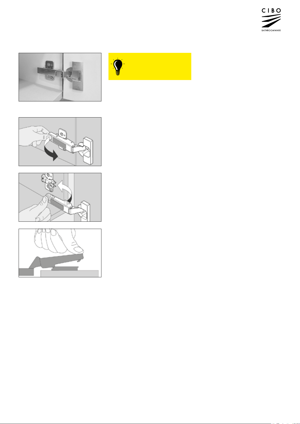
Vanity Unit Type A
Door Removal/Replacement (responsibility of the installer)
4
To Remove Doors
Locate button at back of top hinge and
press. Hold base of door and pull forward
to disengage top hinge.
Repeat with bottom hinge.
To Replace Doors
Line up hinges with corresponding hinge
plates.
At base of hinge is a small metal rod that
must be lined up with cradle arms of
hinge-plate.
Once hinge is in place, push back of hinge
down towards the hinge-plate. Hinge will
snap down and engage.
Capped door hinge
During installation, it is
advisable to remove door(s)
from cabinet. To do this,
unclip all hinges on each door.
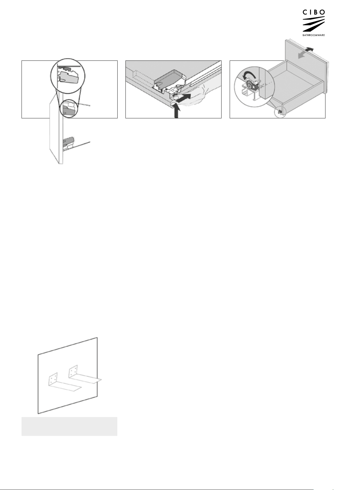
Vanity Unit Type A
Drawer Front Adjustment
5
Special Notes
Vanities that are between two walls (or against a wall to the left or right)
It’s sometimes necessary to construct
the unit with a removable trimming piece
or ller on the side(s) of the cabinet.
This is to allow the installer to trim the
ller should the walls be out of level.
It also is necessary where drawers
are against a wall to prevent the
drawers scraping on the wall.
Units that are between two walls
even when check measured are
unlikely to t immediately.
The llers should be removed by
unscrewing the internal screws.
The llers can be trimmed with an
electric planer to ensure a snug t.
Once the llers have been trimmed,
they are simply reattached to the
vanity with the original screws.
1 Remove vanity drawer and cover
runners (refer to page 3).
2 Detach the chocks (melamine feet)
from the underside of the vanity
(if applicable). They are simply
pinned into the carcass and can be
removed with a chisel and pliers.
3 The unit is to be placed onto the
brackets. Calculate the nished
height of the basin and work space
out where the bottom of the unit will
be (in terms of height). The brackets
should be tted at this level.
4 Screw-x metal brackets to wall
making sure to x into studs
or ample support behind it.
5 Place vanity (without drawer, refer
page 2/3) onto metal brackets and
screw x the vanity to the wall.
6 Remove all debris from drilling
etc. in the vanity cavity; uncover
runners and replace drawer.
7 Seal around unit with silicone.
Vanity Units with a height less than 250mm
THESE UNITS ARE SUPPLIED WITH A PAIR
OF LARGE METAL ANGLED BRACKETS.
1 &2 To raise the drawer front on the
runner, shift the grey clip towards
the back of the drawer.
1
2
3 To change the tilt of the drawer front,
adjust the runners at the back.
1
2
3
This manual suits for next models
3
Table of contents
Popular Indoor Furnishing manuals by other brands

Regency
Regency LWMS3015 Assembly instructions

Furniture of America
Furniture of America CM7751C Assembly instructions

Safavieh Furniture
Safavieh Furniture Estella CNS5731 manual

PLACES OF STYLE
PLACES OF STYLE Ovalfuss Assembly instruction

Trasman
Trasman 1138 Bo1 Assembly manual

Costway
Costway JV10856 manual


