CIGNUS PRO UV-85+ User manual


PREFACE
Thank you for purchasing our Amateur
Portable Radio, which is a dual band/dual
display radio. This easy-to-use radio will
deliver you secure, instant and reliable
communications at peak efficiency. Please
read this manual carefully before use.
The information presented herein will
help you to derive maximum performance
from your radio.

02
CONTENT
1.-SAFETYINFORMATION----------------------iJ,
2.-FEATURESANDFUNCTIONS--------------------n
3AJNPACKINGAND CHECKINGEQUIPMENTS--------------<I
4,OPTIONALACCESSORIES----------------------u,
5.-INSTALLATIONOF ACCESSORIEs------------------n,
5.1.-INSTALLINGTHEANTENNA------------------n,
5.2.-INSTALLINGTHE BELTCLIP-------------------0,
5.3.- MICRO-HEADSET INSTALLATION OF EXTERNAL---------------11,
5.4.-BATTERYINSTALLATION---------------------<I'
6.-BATTERYCHARGIN<..-------------------------0
7.-BATTERYINFORMATION------------------------11;
7.1.-INITIALUSE-----------------------n,
7.2.-BATTERYTIPS---------------------___,,,
7.3.-PROLONGBATTERYLIFE-------------------;,:
7.4.-BATTERYSTORAG'R----------------------n,
8.-PARTS,CONTR.OLSAND KEYS---------------------<I'
8.l.-RADIOOVERVIEW------------------------11'
8.2.-COMMAND/KEYDEFINTIION-----------------10
9.-'LCD' DISPLAY 11 11
10.-1750 Hz TONE FOR ACCESS TO REPEATERS 12
11.- BASIC OPERATIO 12
11.1.-RADIO ON-OFFNOLUME CONTROL 12
11.2, SELECTING A FREQUENCY OR CBANNEL 12
12-ADVANCED OPERATION 12
12.1,SET MEN
U DESCRIPTION 12
12.2,SHORTCUT MENU OPERATION 14
12.3,"SQL" (SQUELCH) 14
12,4.-FUNCTION "VOX" (VOICE OPERATED TRANSMISSIO 14
12.5.- SELECT WIDEBAND OR NARROW BAND "WIN" 14
12.6, TDR (DUAL WATCH/DUAL RECEPTIO 14
12.7.- TOT(TRANSMISSION TIMER) 15
12.8,CTCSS/DCS 15
12.9.-ANI-------------------------15
12.10.- DTMFST (DTMF TONE OF TRANSMITTING CODE) 15
12.11.- SC-REV(SCAN RESUME METIIOD) 15
12.12.- PIT-ID(PTT OR RELEASE PTT TO TRANSMIT THE SIGNAL CODE) 16
12.13-BCL(BUSY CHANNEL LOCKOUT) 16
12.14.- SFT-D(DIRECTION OF FREQUENCY SHIFT) 16
12.15.- OFFSET(FREQUENCY SHIFT) 16
12.16.-STE(STE TAIL TONE ELIMATION) 16
13.-CTCSS TABLE 16
14.-DCS TABLE 17
15.-WALKIE TALKIE WRITE FREQUENCY OPERATION PROCESS 17
15.1.-SYSTEM REQUIREMENTS 17
15.2.-INSTALL THE WRITE FREQUENCY LINE DRIYER 18
15.3.-WRITE FREQUENCY SOFTWARE INSTALLATIO 18
15.4.-WRITE FREQUENCY SOFTWARE OPERATING PROCESS 18
15.5.-RELATED PROBLEM SOLVING 18
15.6.-WBENWRITING THE FREQUENCY IS COMPLETED, FOUND TWO
WALKIE TALKIE CANNOT NORMAL CALL ORRECEIVE---------18
16.-TECHNICAL SPEClFICATION 19
16.1.-GENERAL 19
16.2.- TRANSMITTER 19
16.3.- RECEIVER 19
17.-TROUBLESHOOTING 20
18.-WARRANTY 21
03

04
1.-SAFETY INFORMATION:
The following safety precautions shall always be observed during operation, service and repair of this
equipment.
• This equipment shall be serviced by qualified technicians only.
• Do not modify the radio for any reason.
• Do not use any portable radio that has a damaged antenna. If a damaged antenna comes into contact
with your skin, a minor burn can result.
• Turn off your radio prior to entering any area with e:s:plosive and flammable materials.
• Do not charge your battery In a location with explosive and Oammable materials.
• To avoid electromagnetic Interference and/or compatibility conructs, turn off your radio in any area
where posted notices instruct you to do so.
• Turn off your radio before boarding an aircraft. Any use of a radio must be in accordance with airline
regulations or crew instructions.
• Turn off your radio before entering a blasting areL
• For vehicles with an air bag, do not place a radio in the area over an air bag or in the air bag deployment area.
• Do not expose the radio to direct sunlight over a long time, nor place It close to beating source.
• When transmitting with a portable radio, hold the radio In a vertical position with the microphone 3 to 4
centimeters away from your lips. Keep antenna at least 2.5 centimeters away from your body when
transmitting.
A
WARNING: If you wear a radio on your body, ensure the radio and its antenna are at least 2.5
centimeters away from your body when transmitting.
2.-FEATURES AND FUNCTIONS:
- Dual-band handbeld transceiver with display function menu on the display "LCD".
-DTMF encoded.
-Lithium-ion battery with high capacity.
-Commercial FM radio re<:eiver (65 MHz-108 MHz).
-Incorporates 105 codes "DCS" and SO privacy codes "CTCSS" programmable.
-Function "VOX" (voice operated transmission).
- Alarm function.
-Up to 128 memory channels.
-Broadband (Wide)/ Narrowband (Narrow), selectable.
-fflgb power/ low selectable.
-Display illumination and programmable keyboard.
-Function "beep" on the keyboard.
- Dual Watch/dual re<:eption .
-Selectable Frequency Step 2.S/5/6.25/10/12.S/25 kHz.
-Function "OFFSET" (frequency offset for repeater access).
- Battery saving function "SAVE".
-Timer transmission "TOT" programmable.
-Selecting the Scan Mode.
-Function Busy Channel Lock "BCLO".
-Built-in RX CTCSS/DCS scan
-Built-in LED flashlight.
-Programmable by PC.
- Level Threshold "Squelch" adjustable from Oto 9.
-Crossband re<:eption
-Tone end of transmission
• Built-in key lock
3.-UNPACKING AND CHECKING EQUIPMENTS:
Carefully unpack the transceiver. We recommend that you identify the items listed in the following before
discarding the packing material. If any items are missing or have been damaged during shipment, please
contact your dealers Immediately.
Note:
• Items included in the package, may differ from those listed in the table above depending on the country
of purchase. For more information, consult your dealer or vendor.
4.- OPTIONAL ACCESSORIES:
Note:
• Consult the dealer or retailer for information about options available.
05
06
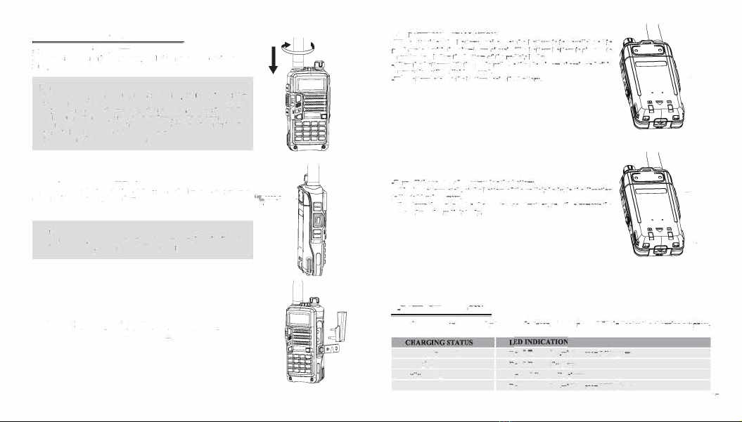
5.- INSTALLATION OF ACCESSORIES:
5. 1.- INSTALLING THE ANTENNA:
Install the antenna as shown In the figure below and turn It clockwise until
It stops.
Note:
-When Installing th
e
antenna, don't rotate it by its top,holdlog It by
its base and turn.
-If you us
e
an external antenna, make sur
e
the 'SWR' is about 1.5:1
or less, to avoid damage to the transceiver's final transistors.
-Do not hold the antenna with your hand or wrap the outside of it
to avoid bad operation of the transceiver.
-Never transmit without an antenna.
5.2.- INSTALLING THE BELT CLIP:
lf necessary, Install the belt clip at th
e
rear of the battery compartment
t
cover as shown in th
e
figure below.
.:.:,;;
-:
-
Note:
-Do not use any kind of glu
e
to fu
th
e
screw on the belt clip. Th
e
solvents Glue may damage the battery casing.
5.3.- MICRO-HEADSET INSTALLATION OF EXTERNAL:
Plug the external micro-headset connector into the jack of 'SP. & MIC'
of th
e
transceiver as shown in the figur
e
below.
S.
4
.- BATTERY INSTALLATION:
-When attaching th
e
battery, make sure the battery is in parallel and in
good contact with the aluminum chassis. The battery bottom Is about I to
2 centimeten below the bottom of the radio's body.
-Align the battery with the guide rails on the aluminum cha.nu and slide
ii upwards until a 'click' is beard.
-The battery latch at the bottom locks the battery.
-Turn off the radio befor
e
removing the battery.
-Slid
e
th
e
battery latch, at the bottom of the radio's body, in the direction
indicated by th
e
arrow.
-SUd
e
down the battery for about 1 to 2 centimeters, and then remove the
battery from the radio's body.
6.-BATTERY CHARGING:
\
\
I
Us
e
only th
e
charger sp
e
cifi
e
d by th
e
manufacturer. Th
e
charg
e
r's LED indicates the charging progress.
Standby (no-load)
Charging
Fully Charged
Error
Red LED ftashes,
whil
e
Green LED glows
Red LED solidly glows
Gr
e e
n LED solidly glows
Red LED ftash
e
s,
whil
e Green LED glows
07

08
Please follow these steps:
1. Plug the power cord into the adapter.
2. Plug the AC connector of the adapter into the AC outlet socket
3. Plug the DC connector of the adapter into the DC sock
e
t on the back of th
e
charger.
4. Place the radio with the battery attach
e
d, or the battery alone, in the charger.
5. Make sure the battery is In good contact with the charging terminals. The charging process initiates
when the red LED lights.
6. The green LED lights about 4 hours later indicating th
e
battery is fully charged. Then remov
e
th
e
radio
with the battery attached or th
e
battery alone from the charger.
7. -BATTERY INFORMATION:
7.1.-INITIAL USE
New batteries are shipp
e
d uncharged fully from the factory. Charge a new battery for 5 hours before initial
use. The ma:l.imum battery capacity and performance is achieved after three full charge/discharge cycles.
Jfyou notice the battery power ruos low, please recharge the battery.
A
WARNING: •
T
o reduce the risk oflnjury,
ch
arg
e
only the batteryspeclfied bytbe manufacturer.
Other batteries may bunt, causing bodUy Injury and property damage.
•To avoid risk of personal Injury, do not dispose of batteri
e
s in a Ore!
-Dispose of batteries according to local regulations (e.g. recycling). Do not dispose as household wast
e
.
-Never attempt to disas1emble the battery.
7.
2
.-BAITERY TIPS:
I. When charging your battery, keep it at a temperature among s• -40•. Temperature out of the limit
may cause battery leakage or damage.
2. When charging a battery attached to a radio, turn the radio off to ensure a full charge.
3. Do not cut off the power supply or remove the battery when charging a battery.
4. Never charg
e
a battery that is wet Please dry it with a soft cloth prior to charge.
S. The battery will eventually wear out. When the operating time (talk•time and standby time) is noticeably
shorter than normal performance, it is time to buy a new battery.
7.3.-PROLONG BATTERY LIFE:
1. Battery performance will be greatly decreased at a temperature below o•. A spare battery Is necessary
in cold weather. The cold battery unable to work in this situation may work under roo
m
temperature, so
keep it for later use.
2. Th
e
dust on the batt
e
ry contact may caus
e
th
e
batt
e
ry cannot work or <:barg
e
. Pl
e
as
e
us
e
a cl
e
an dry
cloth to wipe it b
e
fo r
e
attaching th
e
batt
e
ry to th
e
radio.
7.4.-BATIERY STORAGE:
1. Fully <:barg
e
a batt
e
ry b
e
fo r
e
you store it for a long tim
e
, to avoid batt
e
ry damag
e
du
e
to ov
e
r-discharg
e
.
2. Recharg
e
a batt<:ry aft<:r s
e
v
e
ral months' storag
e
(Li-loo batt
e
ri
e
s: 6 months), to avoid batt
e
ry capacity
r
e
duction du
e
to ov
e
r
-discharg
e
.
3. Stor
e
your batt
e
ry In a cool and dry plac
e
und
e
r room t
e
mp
e
ratur
e
, to reduc
e
self-discharg
e
.
8.1.-RADIO OVERVIEW:
1. antenna
2. flashlight
3. knob (ON/OFF,
v o lume
)
4.
L
C
D
S. SK-side keyl/CALL(radio,alar
m
)
6. SK-side keyl/MONl(flashllgbt,monitor)
7. PTT key(push-to-talk)
8. VFO/MR (frequency mode/channel mode)
9. LED indicator
11
13
10. strap buckle
11.accessory jack
10
18
12.A/B key(frequency display swlt<:hes)
13.BAND key(band switch
e
s)
14.keypad
lS.SP.&MJC,
16.battery pack
17.battery contads
18.battery remove button
09

10
8.2.- COMMAND/KEY DEFINITION:
► [P'ITJ(PUSH-TO-TALK):
Press and hold down the [P'ITJ button to transmit; release it to receive.
► SK-SIDE KEYI/JCALLJ:
-Press the (CALL) button,to activate the FM Radio;Press it again to deactivate the FM Radio.
-Press and hold on the (CALL)button,to activate the alarm function; PTess and bold it agaln,to deactivate
the alarm function.
► SK-SIDE KEY2/)MONI]:
-Press the [MONI] button,to turn on the flashlight;Press it again to turn off.Press and hold on the (MON[]
button,to monitor the signal.
►JVFO/MRJBUTTON:
-Press the (VFO/MR) button,to switch the frequency mode and channel mode.
►JA/BJBUTTON:
-Press the (A/BJ button,to switch frequency display.
►JBANDJBUTTON:
-Press the fBANDJbutton,to switch band dispaly.
-While FM radio being activated,press the [BAND)button to switch the band of FM radio(band 6S- 7SMllvi6-
108MHz).
►J*SCANJKEY:
-Press the [*SCAN) key to activate the Reverse function,it will exchange a separate reception and
transmission frequency.
•Press the (*SCAN] key for 2 seconds to start scanning(frequency/channel).
• While FM radio being activated,press the l*SCAN] key to search FM radio station.
•While setting the RX CTCSS/DCS, press the key (*SCAN] to scan the RX CTCSS/DCS.
►J#.,..o)KEY:
•Under channel mode, press [#rr<>I key to switch ffigb/Low transmit power.
•Press (#rr<>J key for 2 seconds to lock/uolock the keypad.
►FUNCTION KEYPAD:
-JMENU)key:
• To enter the menu of the radio and confirm the setting.
-l•ll•lkey:
•Press and bold [A)or(A)key for frequency up or down fast.
•Press (A)or[A ]key,the scanning will be opposite.
-)EXIT)key:
•
To cancel /clear or nit.
►NUMERIC KEYPAD:
•Used to enter information for programming the radio's lists and the non•
standard CTCSS
•Under transmission mode, press the numeric key to send the signal code(the
code should be set by PC software).
a sum a
CD 0\3 C!J.:lUlil
m a m
111:)
► ACCESSORY JACK:
• The jack
is
used to connect audio accessories, or other accessories such as programming cable.
9.-'LCD' DISPLAY:
The display icons appear when certain operations or specific features are activated.
Icon
188
CT
DCS
+-
s
vox
R
N
KE
A
L
.......
T.,,11
T..111
LDS
vox+-RNBi(]-{)c:::ibE
CT
""'4• -=:4•
-::••-:1i-l75:ss
DCS •-■- ■ ■-
I
•
.:_•- 25 • *
5T2T
14
C"I
1
·-::•C".
1s
:s s
DTMF
'Y
•- ■ ■-■- •- 25 • *
Description
Operating channel.
Operating frequency.
'CTCSS' activated.
'DCS' activated.
Frequency offset direction for accessing repeaters.
Dual Watch/Dual Reception functions activated.
Function 'VOX' enabled.
Reverse function activated.
Wide Band selected.
Battery Level indicator
Keypad lock function activated.
Low transmit power.
Operation frequency.
Signal Strength Level
II

1
2
10.- 1750 Hz TONE FOR ACCESS TO REPEATERS:
The user ne
e
ds to establish long distance communications through an amat
e
ur radio r
e
p
e
at
e
r whic
h
is
activat
e
d after receiving a 1750 Hz tone. Press and hold on the [PTf),
t h en
pr
e
ss th
e
(BM'D] butto
n
to
transmit a
1
750Hz tone.
11.- BASIC OPERATION:
11.t..RADIO ON-OFFNOLU
M
E CONTROL:
-
Make
sure the antenna and battery are installed correctly and the battery charged.
-Rot
a
te the knob clockwise to turn the radio on, and rotate the knob fully counter-clockwise until a 'click'
is heard to turn the radio off. Turn the knob clockwise to increase the volu e, r counter-clockwise to
decrease the volume.
11.2.- SELECTING A FREQUENCY OR CHANNEL,
-Press the key(.&Jorf.A.Jto select the desired frequency/channel you want
The di
s
play shows the frequency
/ ch
a
nnel selected.
-Press
a
nd hold down the key (.A.Jorf.A..] for frequency up or down fast.
Note:
-You can not select a channel if not previously stored.
12-ADVANCED OPERATION:
You can program your transceiver optr
a
t i
n
g In the setup menu to suit your needs or preferences.
12.1.
-S
E T
MENU DESCRIYTION:
Menu Funct
i
on / Descript
i
o
n
SQL (Squelch level)
STEP(Frequency step)
TXP(Transmlt power)
SAVE( Battery save,
1
:
1
/1 :2/1:3/1:4)
VOX(Voice ope
rated
transmission)
WIN( Wideband/narrowband)
ABR(Dlsp
l
ay illumination)
TDR(
D
ual watch/dual ret:ep
ti
o
n)
Avail
a
ble settings
0-9
2.5/5/6.
2S
/
10/
1
2.5/2SkHz
HIGH/LOW
OFF/1/2/3/4
OFF/0-
1
0
WIDE/NARR
OFF/1/2/3/4/Ss
OFF/ON
10
11
12
13
14
1
5
16
17
18
19
20
21
22
23
24
25
26
27
28
29
30
31
32
33
34
35
BEEP(Keypad beep) OFF/ON
TOT(Transmission timer) 15/30/45/60 •• JS85/600seconds
R-DCS(Ret:eption digital coded squelch) OFFffi023N •.. D7541
R-CfS(Ret:eption Continuous Tone Coded Squelch) 67.0H.z. .• 254.IHz
T-DCS(Transmission digital coded squelch) OFFffi023N ••• D7541
T-CTS(Transm.ission Continuous Tone Coded Squelch) 67.0H.z. •• 254.IHz
VOJCE(Voice prompt) OFF/ON
ANJ(Automatic number identific
a
tion of the radio,only can
be set by PC software.
DTMFST(The DTMF tone of transmitting code.) OFF/DT-ST/ANI-ST/DT+ANI
S-CODE(Signal code, only could be set by PC software.) lr··,15 group!!
SC-REV(Scan resume method) TO/CO/SE
P1T-ID(press or release the P1T button to transmit the OFF/BOT/EOT/BOTH
signal code)
PTT-LT(dcl
a
y the 11lgnal code sending)
o,
...
,30ms
MDF-A(under channel mode,A channel displays. Notc:name FREQ/CH/NAME
display only can be set by PC software.
MDF-B(under channel mode, B channel displays. Notc:name FREQ/CH/NAME
di!
l
play only can be set by PC software.
BCL(busy channel lockout) OFF/ON
AUTOLK(keypad locked automatically) OFF/ON
SFf-D(dlrection of frequency shift) OFF/+/-
OFFSET(frequency shift) 00.000 ... 69.990
MEMCH(stored in memory channels) 000, ••• 127
DELCH(delete the memory channels) 000, ••• 127
WT-LED(illumlnation display color of standby) OFF/BLUE/ORANGE/PURPLE
RX-LED(illumlnation display color of reception) OFF/BLUE/ORANGE/PURPLE
TX-LED(illumination display color of transmitting) OFF/BLUE/ORANGE/PURPLE
AL-MOD(alarm mode) SITEffONE/CODE
BAND(band selection) VHF/UHF
TX-AB(transmitting selection while in dual watch/ OFF/A/8
reception)
STE(Tail Tone Elimination) OFF/ON
13
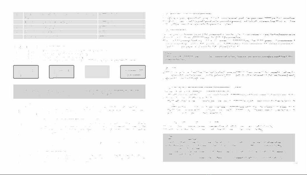
36 RP _STE(Tail tone elimination in communication through OFF/1,2,3 ... 10
repeater)
37 RPT _ RL{Dtlay the tall tone of repeater) OFF/1,2,3 •.• 10
38 PONMGS(Boot display) FULUMGS
39 ROGER(tone end oftnnsmlsslon) ON/OFF
40 RESET (Restore to ddault setting) VFO/ALL
12.2.-SHORTCUT MENU OPERATlON:
].-Press the key MENU,then press the key A or T to select the desired menu.
2.-Press the key MENU again, come to the parameter setting.
3.-Press the key A. or T to select the desired parameter.
4.-Press the key MENU to confirm and save, press the key EXIT to cancel setting or clear the input.
E E E
"MENU
NO. ..
MENU
NO.
.. ..
"MENU
NO.
PARAMEn:R ... PARAMEn:R AllAMEn:R
.
PARAMITER
G) CID @ @
-Note:
Under channel mode,the following menu settings are lnvaHd:CTCSS,DCS,W/N,PTT-ID,BCL,SCAN
ADD TO,S..CODE,CHANNEL NAME.Only the H/L power could be changed.
12.3.-"SQL" (SQUELCH),
-The squelch mute the speaker of the transceiver io the absence of recepdon. With the squelch level correctly
set, you will hear sound only while actually receiving signals and significantly reduces battery current
consumption. It is recommended that you set Level 5.
12.4.- FUNCTION "VOX" (VOICE OPERATED TRANSMISSION):
-This function is not necessary to push the [PTT] on the transceiver for a transmission. Transmission is
activated automatically by detecting the radio voice. When finish speaking, the transmission automatically
terminated and the transceiver will automatically receive signal. Be sure to adjust the VOX Gain level to
an appropriate sensitivity to allow smooth transmission.
12.5.- SELECT WIDEBAND OR NARROW BAND "WIN":
lo areas where the RF signals are saturated, you must use the narrow band of transmission to avoid
interference in adjacent channels.
12.6.-TDR (
D
UAL WATCH/DUAL RECEPTION),
This feature allows you to operate between frequency A and frequency 8. Periodically, the transceiver checks
whether a signal is received on another frequency that we have scheduled. If you receive a signal, the unit
14 will remain in the frequency until the received signal disappean.
12.
7
.- TOT(TRAN SM JSSIO N TIMER),
This function can automatically control the time we transmit each time you press (P1TI on the transceiver.
This feature is very useful to avoid overheating excessive power transiston of the transceiver. The transceiver
will be off transmission automatically once the set time.
12.8.-CTCSS/DCS:
In some cases only want to establish communications in a closed user group at a particular frequency or
channel, ror It will use "CTCSS" or code "DCS" for reception.
The "squdc
b
" opens only when receiving a frequency with "CTCSS" or codes "DCS" same as the programmed
in your transceiver. If codes of the received signal differs from those programmed in your transceiver, the
"squelch" will not open and the received signal can be beard.
Note:
-The use of "CTCSS" or "DCS" in a communication, does not guarantee complete confidentiality
communication.
12.9.-ANI
-ANI (Automatic Number Identification) is also known as PTT ID because an ID is transmitted when the
PTT button of the radio is pressed and/or released. This ID tells the di
s
patc
her which field radio was keyed.
Only could be set by PC software.
12.10.- DTMFST (
D
T
MF TON
E OF TRANSMJTTING CODE),
Finl you should set the PTI-ID as BOT/EOT/BOTH
-"OFF"-Under transmitting mode, you can't bear the DTMF tone, whUe you press the key to transmJt the
code or code automatically traosmJtted..
-"DT-ST"-Under transmitting mode, you can hear the DTMF tone, while you press the key to transmJt
the code.
-" ANI..
S
T
"- und
er transmitting mode, you can hear the DTM
F
tone, while the code automatically tran
s
mitted.
-"DT-ANl"-under transmitting mode, you can bear the DTMF tone, while you press the key to transmJt
the code or the code automatically transmitted..
12.11.- SC-REV(SCAN RESUME METHOD),
This transceiver allows you to scan memory channels, all the bands or part of the bands.
When the transceiver detects a communication, the scan will stop automatically.
Notea:
-"TO" (Time Operation):
Scanninc will atop when Jt detects an active signal The scannlnc will stop on each channel or
active frequency for a predetermined time, after that time the scan will resume automatically.
-"CO" (Carrier Operation):
The scannlnc will stop and remain in the frequency or channel, until the active sle;nal diaappean.
-"SE"(Searcb Operation):
The scanning will stop and remain In the frequency or channel after It detects an active signal.
15

12.12.- PTT-ID(PTT OR RELEASE PTI TO TRANSMIT THE SIGNAL CODE):
-This feature aUows you to know who call you. 14.-DCS TABLE:
-"OFF"-Don't transmit the code while push the PTT button.
-"BOT"-Transmit the code while push the PTT button.(the code only could be set by PC software.) N' Code N' Code N' Code N' Code N' Code
-"EOT"-Transmit the code while release the PTT button.
-"BOTH"-Transmit the code while push or ttlease the PTT button.
12.13.- BCL(BUSY CHANNEL LOCKOUT): D02JN "
DJJIN 43 DlSIN
..
D371N 85
D532N
The BCLO feature prevents the radio's transmitter from being activated if
a signal strong enough to break
through the "noise" squelch is present. On a frequency where stations using different CTCSS or DCS codes D025N
23 D132N 44 D252N
..
D4UN
.. 0546N
may be active, BCLO prevents you from disrupting their communications accidentally (because your radio
D026N 24 D134N
.. D255N ..
D412N 87 D565N
may be muted by its own tone decoder). D031N ,.
D143N
..
D261N 67 D413N
.. D606N
12.14.-SIT-D(DIRECTION OF FREQUENCY SHIFT):
The "OFFSET" is the difference or offset between the re<:eption frequency and the frequency of
DOJlN
,.
D14SN 47 D263N
..
0423N
..
0612N
transmission for access to amateur radio repeaten. Set the "OFFSET" according to the "OFFSET" amateur D036N 27
D152N
.. D265N
69 D431N
.. D624N
radio repeater through which want to communicate.
12.15.- OFFSET(FREQUENCY
stDFn:
0043N ,.
DISSN
•• 0266N 70 0432N
91 0627N
When communicating via a repeater, the direction of displacement of frequency should be timed to the
displacement of the transmission frequency is higher or lower than the receiving frequency. 0047N ,.
D156N
..
D271N 71
DUSN ., 0631N
example: DOSlN 30
0162N 51 0274N 72
D446N ., 0632N
U we want to make a communication through amateur radio repeater whose frequency input is 145,000 10 0053N
31
D165N
., D306N 73
IU52N
.. D64SN
MHz and 145,600 MHz is output, we select the "OFFSET" of the previous section In 0600 and the direction
of travel "SHIFT" programmed to 1-1, so the transceiver will always 145,600 MHz In frequency and when
11
D054N
32 0172N 53 O3llN 74
0454N .. D654N
you press [P'ITJ to transmit transceiver, the frequency will automatically move to
145,000 MIiz
12
0065N 33
D174N 54 D315N 75 IU55N
.. D662N
12.16.-STE (TAIL TONE ELIMATION):
13
D071N
34
O20SN 55 O325N 76
D462N ., D664N
This function Is used to activate or deactivate the transmission end of the transceiver. this final tone
transmission only be used In communications between transceivers and not in communications through a 14 0072N
35
D212N
..
D331N 77
0464N ..
D703N
repeater, which must be deactivated.
15
D073N
36 O223N 57 O332N
,. 0465N ..
O712N
13.-CTCSS TABLE: 16 D074N 37
D225N
..
D343N
,.
D466N
100 D723N
N' Tone(Hz) N' Tone(Hz) N' Tone(Hz) N' Tone(Hz) N' Tone(}h)
17 Dtt4N
38
O226N
.. D346N .. 0503N 101
O731N
67.0 11
94.8
21 131.8 31 171.3 41 203.S
18
Dll5N 39 D243N
..
D351N
81
0506N
102
D732N
69J 12
97.4
"
136.5 32 173.8
"2116.S
71.9 13 100.0 23 141.3
33 177J
43 210.7 19 Dtt6N
... D244N 61
O356N 82 DS16N
103
O734N
74.4 14 103.s 24 146.2
34
179.9
44
218.I
20
D122N
41
D245N
62 D364N 83 D52JN 104
D743N
77.0 15 107.2 25 151.4 35 183.5 45 225.7 21 O125N
"D246N
63
D365N .. D526N 105
O754N
79.7 16 U0.9
"156.7
36
186.2
46 229.l
82.5 17 114.8 27 159.8
37
189.9 47 233.6
15.-WALKIE TALKIE WRITE FREQUENCY OPERATION PROCESS:
85.4
18
118.8
28
162.2
38
192.8
48
241.8
15.1.-SYSTEM REQUIREMENTS
88.5 19 123.0
"165.S
39 196.6 49
250J Operating System :Windows98, Windows Me, Windows XP, Windows Vista, Windows7, Windows8
10 91.S
20
127.3
30
167.9
40 ,,.., 50 254.1 Hard Disk Space: At least 50MB of available .
16 The minimum memory: 64M 17
15.2.-INSTALL mE WRITE FREQUENCY LINE DRIVER
1. Find the write line drive which your system corresponded to
2. Click to install, successfully installation is ok
1S.3.-WRITE FREQUENCY SOITWARE INSTALLATION
Programming cable readying
-1.
USB Programming cable- need to install the driver before they write frequency
-2. &:!rial port Programming cable does not need to install the driver,
it
can direclly write
Computer terminal preparations
-t. Open the computer, run the computer operating system.
-2. Install the write frequency software wblcb bas been downloaded well or Install
it
From the programmlog
software CD
-3. installed, and open the write frequency software programming interface
Walkie Talkie end preparations
-1. USB(or serial)Programmlng cable connect the computer end
-2. The USB Programming cable pin is connected with one end of the walkie talkJe programming interface
-3. Ensure the walkJe talkie under the condition of power, open it.
15.4.-WRITE FREQUENCY SOFTWARE OPER
A
TIN G PROCESS
1. Find the software settings, open communication port, to ensure the communication port Option and
computer connection port conslstent (inconsistent will not read frequency) to solve the related problem
2. In the menu to flnd reading frequency and click in the window that appears can reading frequency
3. This process needs waitting for a while, after the completion of reading the progress bar shows the walkJe
talkie channels and frequencies that have been read into the current software
4. Modify the walkie talkie channel and frequency data, and other functional parameter data
S. Find the write fre
q
uen
cy
in the menu ,click the appeared window to confirm, complete the progress bare
6. lf multiple wallde talkie needs the same frequency, frequency steps can be repeated lo write
15.5.-R
E
L
A
TED PROBLEM SOL YING
When reading or writing frequency ofwalkie talkie long time no response or a communication error?
l.
check lhe write frequency line to find if it it damaged
l. check wether the write frequency line with computer IC!ri.al port or walkie talkie interface is bad or loose
3. Check to ftnd whether the walkie talkie battery is low or out of power, If this ,please replace the battery
or charging the battery
4. Check whether the programming software Is match with the current model
5. Please check whether the write frequency software port settings are assigned to the computer USB port
6. Please check whether the power i.s switched on the walkie talkie
7. Whether to choose the corresponding drive system and the correct installation
15.6.-WHEN WRITING THE FREQUENCY IS COMPLETED, FOUND TWO WALKIE TALKIE CANNOT
NORMAL CALL OR RECEIVE
1. Make sure whether the two walkie-talkie are in the same channel
2. Determine the same channel at the receiving end CTCSS, CDS and the trantmitter is not the same
3.
make sure whether the two walkie talkie' volume is too low, if it ill too low ,Turn on the volume
4. Please check whether the two walkie-talkies are open, or at low/no power status
S. Check wether The walkie-talkie Installed antenna
18 6. check and confirm wether the communication di
s
tance Is too far
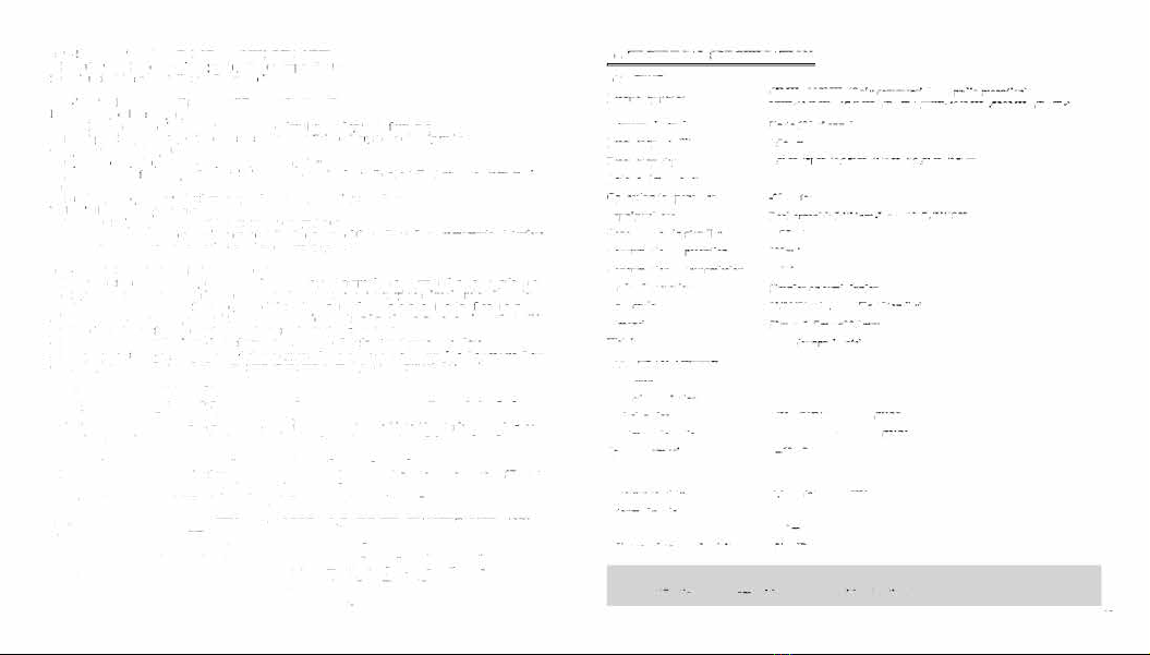
16.-TECHNICAL SPECIFICATION:
16.1.-GENERAL,
Frequency range
Memory channels
Frequency stability
Frequency step
Antenna impedance
Operating temperature
Supply voltage
Comumpdon in standby
Consumption in reception
Consumption in transmission
Mode of operation
Duty cycle
Dimensions
Weight
16.2. -TRANSMIITER:
RF power
Type of modulation
Emissionclus
Maximum deviation
Spurious emissions
16.3. -RECEIVER,
Receiver sensitivity
Intermodulation
Audio output
Adjacent channel selectivity
Note:
6SMHz..108MHz(Only commercial FM radio reception)
VHF:136MHz-174MHz (RxlTI).
UHF
,400MHz -520MHz (lWTx)
Up to 128 channels
2.5ppm
2.
Skll7JSkH7J6
.2SkHz/t0kH7./ 12.
5k H r
/ 2S
kHz
500
-20 't to +60 't
Rechargeable Lithium-Ion mAh 7.
4V
/1800
'!:::75mA
380mA
'!:::t.4A
Simplex or semi-duplex
03/03/54 min.
(Rx/
Ts: / Standby)
59mmxl 17mmx29.5mm
208 g (appro.rimate)
SW
FM
16K<l>F3E/11K<l>F3E (WIN)
'!::: ± S klh/'!:::
±
2.5 kHz (WIN)
<-60 dB
0.
2
µ V(at 12 dB SINAD)
60dB
lOO0mW
6S/60dB
-All tpedflcadont tbowa are subject
lo
change without notiu.
19

20
17.-TROUBLESHOOTING:
Problem
The radio does not start.
The battery runs down quickly.
Possible cause / solution
The battery is low, replace the battery with a charged battery or
proceed to the battery.
The battery is not installed correctly, remove the battery and
reattach it.
The battery life has come to an end, replace the battery with a
new one.
The battery Is fully charged, make sure the battery Is made tn fulL
Make sure the volume setting Is too low.
The receiving indicator LED Hghts Make sure the undertones "CTCSS" or code "DCS" are the same
but do not hear the speaker. as those programmed in the transceiver of the other members of
your group.
When transmitting, the other
members of his group do not
receive the communication.
In"standby"mode, the transceiver
transmits without pressing the
"PTT".
Receive communications from
other user groups while
communicating with your group.
Communication with other
memben of your group is poor or
low quality.
Make sure the undertones "CTCSS" or code "DCS" programmed
in your transceiver are the same as those programmed in the
transceiver of the other memben of your group.
Your partner or you, are too far.
You or your partner are in a bad area of RF signal propagation.
Check the level adjustment function "VOX" ii not set too sensitive.
Change frequency or channe
l
Change tbe undertones "CTCSS" or code "DCS" in your group.
You or your partner is too far away or in an area of poor radio signal
propagation, such as inside a tunnel, inside an underground car park.
in a mountaino111 area. including large metal structures, etc..
Once these checks, if you still have problems with the transceiver, check with your distributor, dealer
or service center.
18.-WARRANTY: (Better buy the radios from local dealer).
WARRANTY CERTIFICATE
Brand: Model no.:
Name of purchaser:
Address:
City: Zip code:
Province/State: Tel no.:
Date of purchase:
WARNING: Warranty is valid provided it is complete and
properly filled in legibly and clearly present the seal and
name of
the dealer and have attached the bill proof of
purchase of equipment.
Serial no.:
I and name of
the dealer
The device described in this Certificate is guaranteed for a period of one year from the date of sale to the final
user.This Warranty Certificate is unique and not transferable and may not be reissued for new or original or
copy. Substitution of product failure or any part thereof shall not involve extension of the guarantee.
The warranty covers the replacement and free replacement of all parts that are defective in materials and
components used In manufacturing and/
or assembly of
the apparatus.
The warranty does not cover any faults caused by accident, Improper Installation and use, electric shock (cg
storms), connect a power other than that specified, reverse polarity in the diet, or claims due to deterioration in
the external appearance of normal use, nor the amount or condition of the accessories.
Checking the accessories ii the responsibility of the purchaser at the time of purchasing the device.
The warranty does not cover rechargeable batteries even if they are part of the equipment purchased as they
are considered consumables, the impairment mwt be reported within a period of fifteen days from the date of
purchase.
The warranty Is void on the following assumptions:
1. -Devices that have been manipulated by another or by anyone other than authorized service provider.
2. -Equipment and accessories in which the serial number has beeo altered, deleted or med unreadable.
3. -Use of the product than as intended.
To make use of
the guarantee is necessary to give the dealer or any of the Authorised Service the defective device
with its accessories and the foUowing documentation:
1. -Warranty Certificate duly completed and sealed.
2. -Original Invoice whkh clearly identifies the device and the date of purchase.
3. -Description of the faults.
The warranty terms contained in this Certificate of Guarantee do not exclude, modify or restrict the statutory
rights of the buyer by virtue of the Jaws in force at the time of purchase, but are added to them.
21
Table of contents


