Cimarron C Plus I User manual
Page | 1
CPlus
with
TRANSLATOR OPTION
Service and Installation Manual
Manual Revision Mar 2014
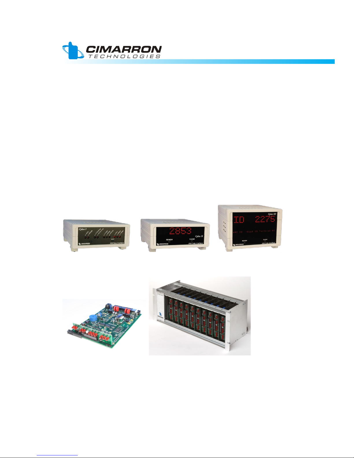
Available for the following products:
© 2013 Cimarron Technologies Corp., Escondido, CA, USA.
All rights reserved. No part of this manual may be reproduced in any way without the express written
permission of Cimarron Technologies Corporation.

Page | 2
Cimarron Technologies Inc.
934 S. Andreasen Suite G
Escondido, CA 92029 USA
Voice: 760-738-3282 (Sales)
760-738-3283 (Service)
FAX: 760-480-0233
Email: service@cimtechcorp.com
Web: www.cimtechcorp.com
Cimarron Technologies Corporation is a licensee of the Motorola MDC-1200Protocol
technology.
MDC-1200® is a registered trademark of Motorola Inc.
GE Star® is a registered trademark of General Electric Corporation
Manual revision Translator Cplus Mar 2014
Revision
Date
Description
6/3/13
Updated. Major re-edit with many simplifications.
9/25/13
More refinements.
11/11/13
Added $$F description.
Mar 2014
3/19/14
Major updating. Mute relay timing diagrams added.

Page | 3
Contents
SECTION 1 – DESCRIPTION....................................................................4
SECTION 2 – SPECIFICATIONS...............................................................6
SECTION 3 – INSTALLATION – SINGLE ENDED....................................7
SECTION 4 – BALANCED.........................................................................8
SECTION 5 – DATA INPUT - DETAILS ..................................................10
SECTION 6 – DATA OUTPUT - DETAILS...............................................12
SECTION 7 – PROGRAMMING...............................................................13
SECTION 8 – OPERATION .....................................................................17
SECTION 9 – SERIAL PORT...................................................................21
SECTION 10 – TROUBLESHOOTING ....................................................22
SECTION 11 – SCHEMATICS.................................................................24
INDEX ......................................................................................................29

Page | 4
SECTION 1 – Description
The Translator feature changes the basic function of the CPlus series decoders.
The CPlus Translator converts an ANI burst FleetSync, GE-Star, or DTMF
(referred to as “Incoming ANI”) into MDC-1200 so that the signal can be decoded
at a dispatch console capable of only MDC-1200 signaling.
The Translator operates in parallel with the Audio In of the console. The parallel
configuration means that the console will see Incoming ANI and the translated
MDC-1200 data bursts. The translator does not stop the Incoming ANI bursts
from reaching the console.
The Translator contains a Mute Relay to allow most of the incoming data burst to
be silenced at the console speaker audio. The effectiveness of the muting
function is highly dependent on the console audio circuitry. Depending on the
console, the incoming data bursts may or may not be heard by the dispatcher.
Voice audio will pass directly to the console. Voice audio does not pass through
Translator. Voice audio is not muted or affected in any way by the Translator.
The Dispatch console will normally hear 2 data bursts. The 1st will be the
Incoming ANI data, the 2nd will be the MDC-1200 burst. The processing time of
the Translator creates a delay between the data bursts that prevents any overlap
of the 2 data bursts.

Page | 5
Operation Example:
A unit in the field with FleetSync signaling keys up and his PTT ANI is
transmitted. At the Translator, the FleetSync ANI is decoded and converted to
MDC-1200 and the resulting ANI burst is injected into the audio path
approximately 300 mS later. As FleetSync is not recognized by the dispatch
console it is ignored and the MDC translation is displayed at the console.
Notes:
•The RS-232 serial port is for initial set-up only.
•Can be implemented with a CPlus I, II, III, or MCI.
•C Plus series takes in FleetSync or GE-Star or DTMF and always
outputs MDC-1200
•Alias option not available with the Translate option.
•No Acknowledgements, no sounder, no contact closures.
•No special reactions to Emergencies (no acknowledgements)
•FleetSync’s 3 digit Fleet ID will be ignored.
•Not compatible with FleetSync II.

Page | 6
SECTION 2 – Specifications
Input Data Formats: FleetSync, GE-Star, DTMF
(Not compatible with FleetSync II)
Output Data Format: MDC-1200, ID up to 4 hex characters
Display Type: Dependent on unit that Translate is installed into
Emergency: No special reactions.
Acknowledgements: None.
Translation Delay: FleetSync ~ 300 mS
Ge-Star ~ 170 mS
Mute Reaction: FleetSync ~ 55 mS
GE-Star ~ 45 mS
Sounder: Yes.
Data Input: Single ended: 30mv to 12Vpp
Balanced: 600 Ω:-30 to +10dBm;
Hi Z: -36 to +4dBm
Data Output: Single ended: 600 Ω: to 14Vpp
Balanced: 600 Ω: to +10dBm;
Hi Z: to +16dBm
Serial Interface: RS-232, via RJ-11
Dimensions: 7.87” x 6.25” x 2.5” (Cplus I, II)
7.87” x 6.25” x 4.75” (Cplus III)
7.87” x 5.0” x 1.1” (MCI CH card)
Mute Relay: Form C, 1 NO. 1 NC contact
Power Requirements: 5 VDC ±5% at 700 m A (Cplus I, MCI CH card)
5 VDC ±5% at 1.2 A (Cplus II)
5 VDC ±5% at 1.5 A (Cplus III)
Page | 7
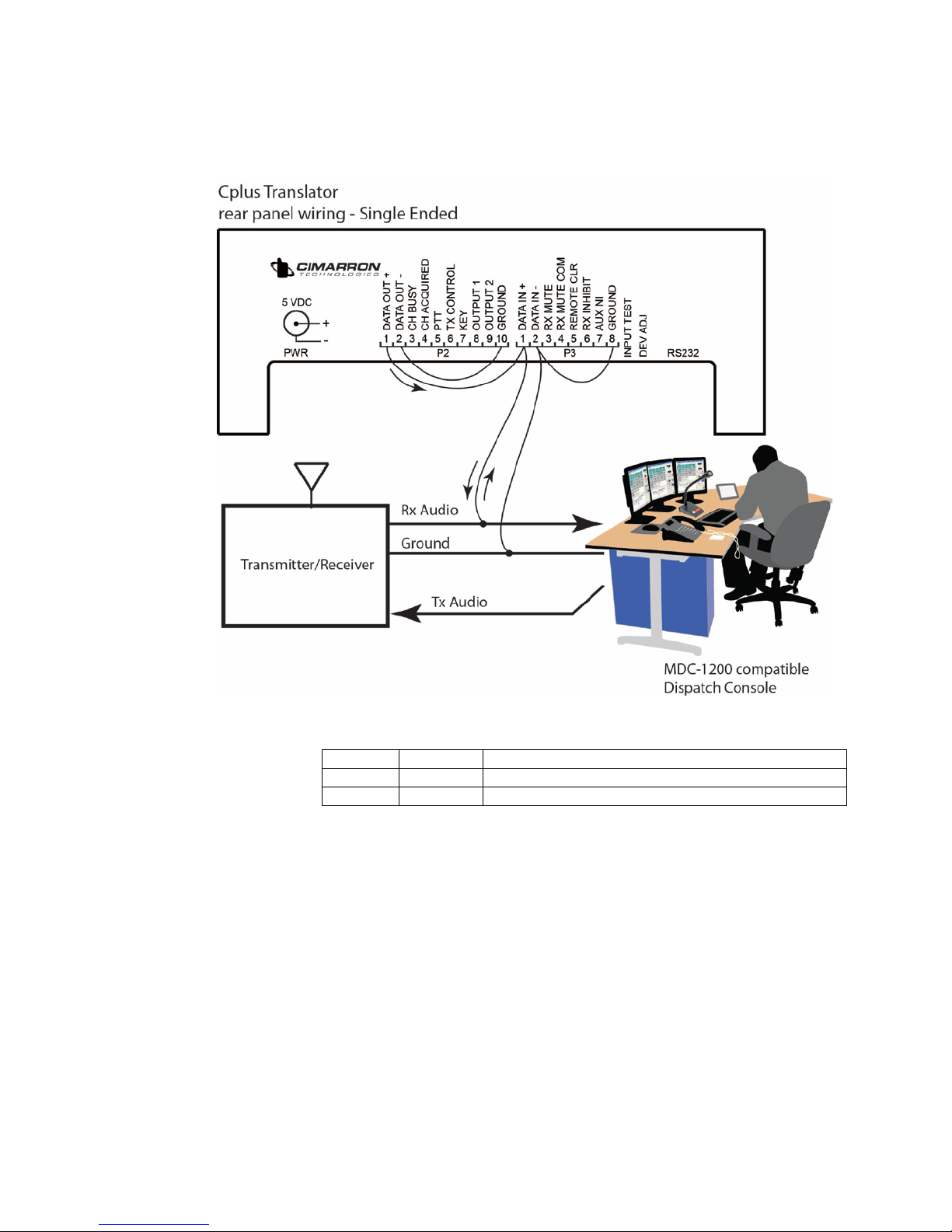
SECTION 3 – Installation – Single Ended
Single Ended jumpers:
Jumper
Purpose
JP-7
Install
References the data in common line to ground.
JP-25
Install
References the Data Out common line to ground.
For a Single Ended, 600 ohm installation, please contact
Cimarron’s Engineering Department for assistance.

Page | 8
SECTION 4 – Balanced
Balanced connection jumpers. These will result in a High Z connection.
Jumper
Purpose
JP-8, JP-24, and JP-27
Install
Configure input and outputs circuits for Balanced
Hi-Z.
JP-7, JP-11, and JP-25
Remove
Configure input and outputs circuits for Balanced
Hi-Z.
P3-8 to station ground
Add
Required system ground.
For a Balanced, 600 ohm installation, please contact Cimarron’s
Engineering Department for assistance.

Page | 9
Jumpers:
Jumper
Default
Purpose
JP-5
8-7 In
6-5
4-3
2-1
Provides 0dB of gain.
Provides 12dB of gain.
Provides 24dB of gain.
Provides 36dB of gain.
JP-8
Out
Adds 6 dB of attenuation to the Data In signal.
For use only in Balanced systems.
JP-9
Out
Adds 12 dB of attenuation to the Data In signal.
For use only in Balanced systems.
JP-10
Out
Adds 18 dB of attenuation to the Data In signal.
For use only in Balanced systems.
JP-11
In
Adds 6 dB of attenuation to the Data In signal.
For use only in Single Ended systems.
JP-12
Out
Adds 12 dB of attenuation to the Data In signal.
For use only in Single Ended systems.
JP-13
Out
Adds 18db of attenuation to the Data In signal.
For use only in Single Ended systems.
Jumpers JP-13, 12, 11, 10, 9 and 8 set up attenuation circuits. Only
one of these jumpers should be installed. JP-11, 12 and 13 are for
Single Ended systems and JP-10, 9 and 8 are for Balanced
systems.

Page | 10
SECTION 5 – Data Input - Details
Data input is the signal input to the C Plus. This is Receive Audio
from the radio. Data In + is the high side and Data In - is the low
side. Data input is jumper selectable for high impedance single
ended, high impedance balanced and 600 ohm balanced. In non-
balanced configurations, Data In - is referenced to ground.
However, note that it is not directly shorted to ground. In balanced
systems, it is signal return. Always attach an independent station
ground to the rear panel P3 pin 8 or P2 pin 10.
The input is capacitor coupled for DC blocking and is MOV
protected. When interfacing to a radio, connection should be
receive audio, before de-emphasis (flat audio). Data input + should
be jumped for high impedance and data input – should be jumped
to ground.
If connected to a balanced line, remove ground jumper JP-7.
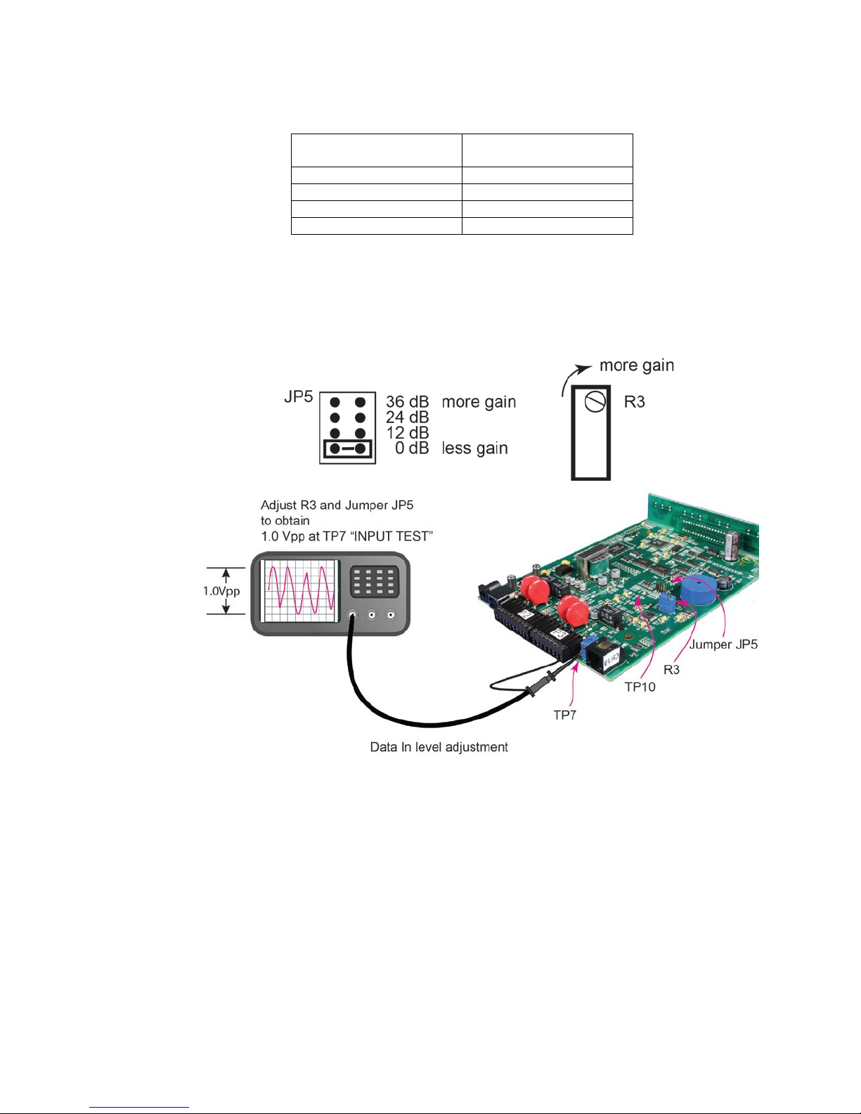
Data input is AGC conditioned so generally, no adjustment is
necessary. A test point is provided for oscilloscope connection. If
the signal is clipped and distorted, a potentiometer and a bank of
gain jumpers can reduce gain. Alternately, if the signal is too weak,
gain can be increased.
Attenuation jumpers are described below. Use only one jumper at a
time.
Input Signal Attenuation
Unbalanced
Balanced
18 dB
JP-13
JP-10
12 dB
JP-12
JP-9
6 dB
JP-11
JP-8
Page | 11
JP5 provides an amplification stage to increase the data input
signal. Amplification factors are described below.
Observed Maximum
signal at TP10
Gives this amplification
to input
0.05 VPP
36 dB
0.2 VPP
24 dB
0.65 VPP
12 dB
1.6 VPP
0 dB
If you experience a decode rate of less than 100%, view the ANI
signal waveform at TP10. Adjust the attenuation jumpers so that
the waveform is not clipped. Do not exceed the absolute maximum
peak to peak signal level listed in the above table. Then view the
waveform at TP-7 and adjust jumper JP-5 and VR3 for a 1 Vpp ANI
signal.
Page | 12
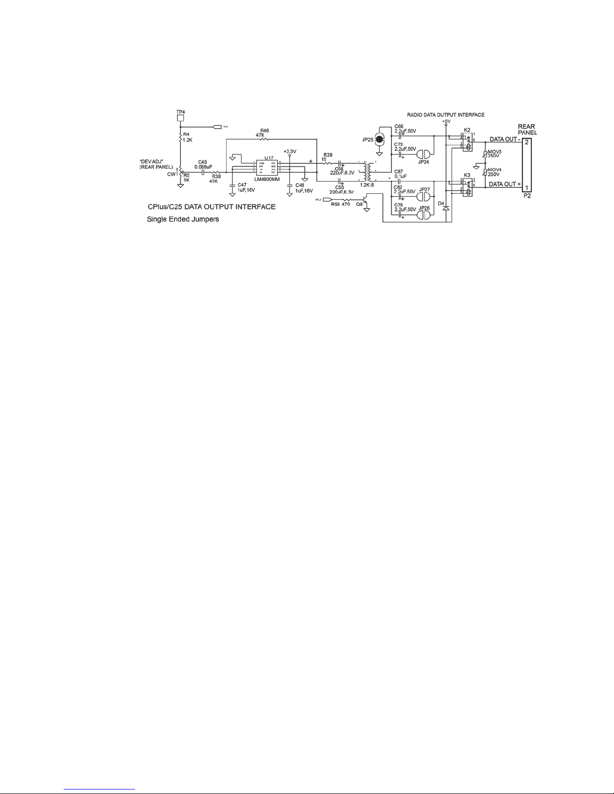
SECTION 6 – Data Output - Details
Data output is the translated MDC-1200 ANI burst out of the C Plus.
Data output is jumper selectable for single ended or balanced
configurations. In Single Ended configurations, Data Out - is
referenced to ground. However, note that it is not directly shorted to
ground. In balanced systems, it is signal return. Always attach an
independent station ground to the rear panel P3 pin 8 or P2 pin 10.
The output is capacitor coupled for DC blocking, is MOV protected
and is completely isolated by relays when not actively encoding.
If connected to a balanced line, remove ground jumper JP-25. For
600 ohm operation, add jumpers JP-24 and JP-27.
Data output must be adjusted to ensure that the target console sees
a level about the same as the un-translated burst. Rear panel
potentiometer R5 is available to adjust the level.
The Self-Test command $$KEYT is used for setting outbound data
deviation. This command forces a 10 second burst of data from the
Cplus.
Page | 13
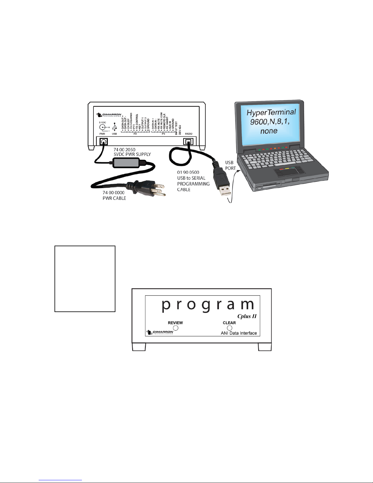
SECTION 7 – Programming
The C Plus is set-up via the RJ-11 RS-232 serial connection. The
RJ-11 serial connection can be used with any computer running
terminal emulation software like “Hyperterminal”.
Upon initial power-up, the C Plus counts down for 10 seconds. After
the countdown, the C Plus is ready.
To program the C Plus, type:
$$CPlus
The Cplus display will show the word:
When in program mode, the C Plus suspends normal
operation until program mode is exited.
The following menu will appear on Hyperterminal:
Note: Not all programming items are available for the Cplus Translator.
When Using
Hypertermal,
characters you
type will not
be visible on
the computer
display.

Page | 14
Programming the C Plus Personality
The C Plus is shipped with the default format type = “MDC-1200”. This is
the correct setting to translate FleetSync, GE-Star, or DTMF.
Note: Not all programming items are available for the C Plus
Translator.
To confirm the C Plus personality, from the main menu, type a “2” to
select:
2. PROGRAM THE CPLUS PERSONALITY
The following menu appears:
C PLUS PERSONALITY PROGRAMMING
1. SELECT FORMAT TYPE
2. SELECT OUTPUT TYPE
3. SELECT DISPLAY TYPE
4. SELECT MUTE TYPE
5. DEFINE SERIAL PORT PARAMETERS
6. DEFINE RADIO INTERFACE
7. ASSIGN PORTS
8. ASSIGN CHANNEL NUMBER
9. ASSIGN BASE ID NUMBER
A. ENABLE/DISABLE SOUNDER
PRESS BACK SLASH "\" TO GO BACK
OR PLEASE ENTER YOUR SELECTION:_
1. SELECT FORMAT TYPE The following menu appears:
SELECT FORMAT TYPE
1. GE STAR
2. GE STAR NYSP
3. MDC-1200
4. FLEETSYNC
5. DTMF
Your current selection of format type is:_3
Press back slash "\" to go back
Or enter 1-3 for a new selection of format
type:_
MDC-1200 is correctly selected!

Page | 15
In addition to FleetSync, you may enable the Translator to translate GE-
Star and/or DTMF data into MDC-1200 as follows.
1. SELECT FORMAT TYPE The following menu appears:
SELECT FORMAT TYPE
1. GE STAR
2. GE STAR NYSP
3. MDC-1200
4. FLEETSYNC
5. DTMF
Your current selection of format type is:_3
Press back slash "\" to go back
Or enter 1-3 for a new selection of format
type:_
Select: “1. GE STAR”
and/or
Select: “5. DTMF”
Although the Translator is now programmed for up to 3 formats,
the Menu will always return “MDC-1200” as the selected format.

Page | 16
Unique Settings for FleetSync
FleetSync contains Fleet ID’s which cannot be supported by the structure
of MDC-1200. This requires the translator to strip the Fleet ID from the
received data string and forward only the unit ID.
To support Fleetsync group ID translation, up to ten ID translations can
be entered into the C Plus. ID translations are defined by entering the
following string:
$$Fxxxx=Myyyy
Where:
xxxx is the four digit FleetSync target group ID
yyyy is a four digit MDC-1200 group ID.
If a FleetSync group call is received targeting group xxxx, the translator
will substitute MDC ID yyyy for that translation.
For example, $$F4911=ME123 will permit FleetSync group ID 4911 to be
translated into MDC group ID 123. MDC-1200 ID’s that begin with “E”
represent MDC groups.
An existing table can be read from the C Plus by entering the string:
$$FVIEWGROUPS
The table can be deleted by entering the following string:
$$FERACEGROUP
If DTMF mode is selected, the following programming options must be
considered:
Unique Settings for GE-Star
The GE-Star format has many variations which most users will never be
involved with. If you believe your system to use one of the less common
variations, contact the Cimarron Technologies Engineering Department
and we will be glad to help you program the Translator.
Unique Settings for DTMF Mode
The DTMF format has many non-standard timing variations which most
users will never be involved with. If you believe your system uses one of
the less common character timings, contact the Cimarron Technologies
Engineering Department and we will be glad to help you program the
Translator.
ID Qualifying is a type of filtering which is available in the Translator. If
you believe your system would benefit by the use one of the filter,
contact the Cimarron Technologies Engineering Department and we will
be glad to help you program the Translator.

Page | 17
SECTION 8 – Operation
Front Panel Displays and Controls
C Plus I - Translator
The C Plus I - Translator is a computer interface device. The front panel
consists of LED Indicators describing the functioning of the unit. The
LED’s and their function are as follows:
LED
Indicator
Meaning
MUTE
Lights when the C Plus detects data which may or may not
decode. Stays lighted during the entire reception period.
Follows the action of the Mute relay.
DECODE
Lights when the C Plus has successfully synchronized with
incoming data and is decoding valid data.
Tx I/O
ACTIVE
Lights when the C Plus is providing data to the RJ-11serial
port.
Rx I/O
ACTIVE
Lights when the C Plus is detecting data from the RJ-
11serial port.
Tx BUSY
Indicates that the attached transmitter is busy.
KEYED
Indicates that the C Plus is keying the attached transmitter
ENCODE
Indicates that the C Plus is modulating data for
transmission.
AUX 1
Not active.
ERROR
Flashes when there is an equipment failure.
POWER
Indicates that the unit is powered on.
RESET
button
Resets the CPU.
Page | 18
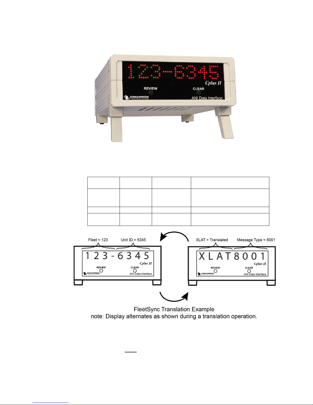
C Plus II - Translator
The C Plus II Translator showing a pre-translated FleetSync ID = 123-
6345. This ID will be translated to MDC-1200 ID = 6345.
Signaling
type
Typical
Display
Translation
Comments
FleetSync
123-6345
6345
A PTT ID has been received
from radio whose fleet number
is 123 and ID is 6345.
GE Star
1234
1234
MDC-
1200
A876
A876
MDC-1200 ID’s are in
hexadecimal.
In operation the C Plus II will alternate between the decoded ID and the
abbreviation “XLAT” and the decoded ID Message type. The Translated
MDC-1200 ID is not displayed.

Page | 19
The RS-232 port will show the decoded ID. The RS-232 port will not
show the translated MDC-1200 ID.
The C Plus II has two push buttons on the front panel. The right button
is labeled CLEAR and clears the display.
The left button is labeled REVIEW and when pressed, steps the display
through the last 20 received messages. Messages are displayed just as
they were received except the left most display shows the order in which
the messages were received. The most recent message will be labeled
“a”. Subsequent messages will be labeled “b”, “c” and so forth. To
facilitate speedy review, non-PTT messages alternate in 1-second
intervals between ID/alias and message type instead of 2-second
intervals.
To clear the review buffer, press and hold the review button while
pressing the clear button. The review memory will be erased. The
review buffer resides in SRAM and as such is volatile. If power is lost or
removed, the review buffer will be erased.
Page | 20
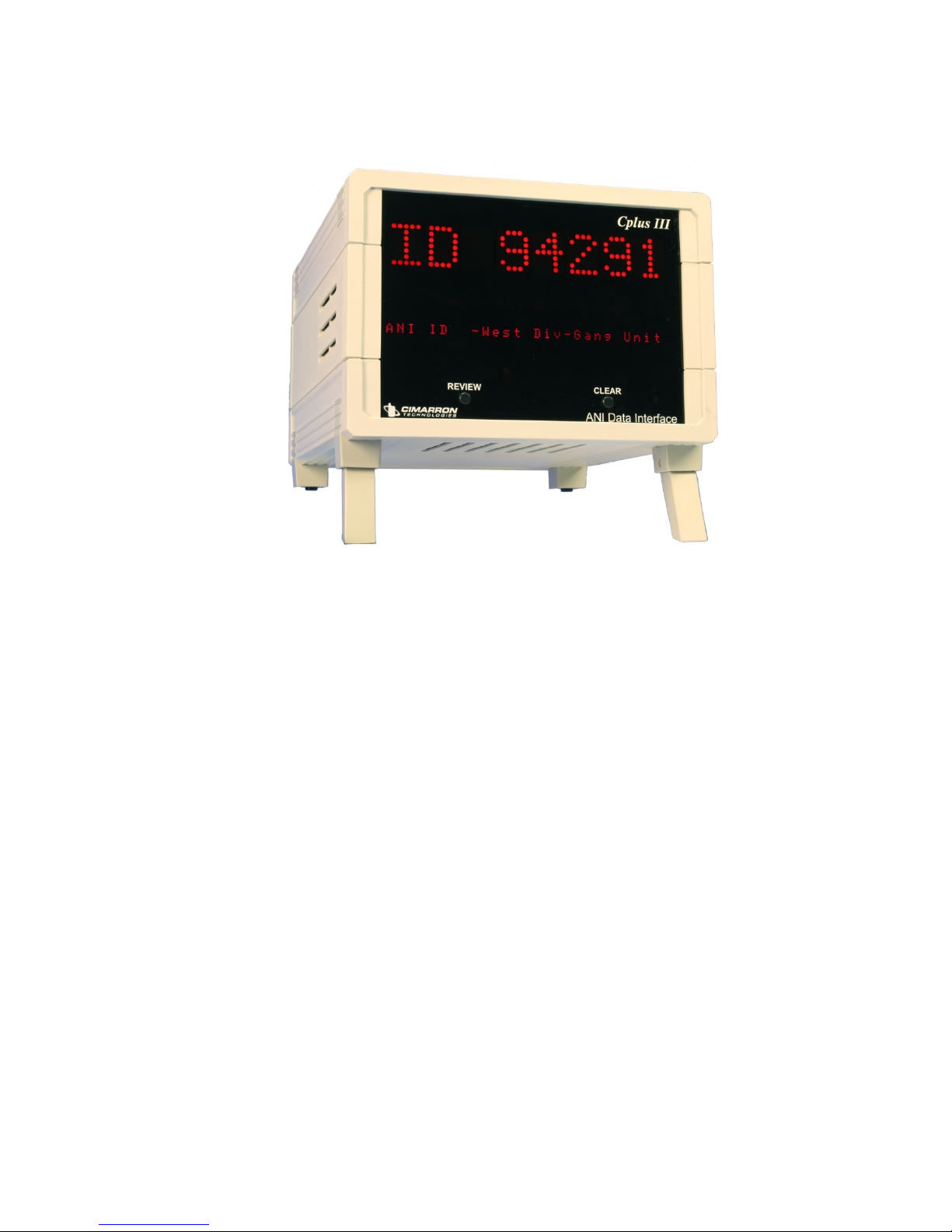
C Plus III - Translator
The C Plus III is a multiple window dispatch display unit. The main
display and its features are the same as the C Plus II. In addition to the
main display, there is a secondary, smaller display capable of displaying
28 characters just above the two push buttons. This display area is user
programmable to present two different features.
This manual suits for next models
2
Table of contents
Other Cimarron Media Converter manuals

Popular Media Converter manuals by other brands

Hama
Hama 80049284 Operating instruction

Transition Networks
Transition Networks SFMFF4040-100 user guide

Microflex
Microflex 101-0010 Installation and operation manual

geratech
geratech EGE-DVI-142DL-144DL instructions

YASKAWA
YASKAWA U1000 iQpump Drive quick start guide

Muenled
Muenled LEDsync822A user manual

Siemens
Siemens SINAMICS G120D operating instructions

Verint
Verint S1801e Quick installation guide

PALAB
PALAB CANARY DA-1 D/A user manual

Key Digital
Key Digital KD-FIX418A operating instructions

Littfinski Daten Technik
Littfinski Daten Technik SA-DEC-4-MM-B Assembly instruction

Mitsubishi Electric
Mitsubishi Electric MELSEC iQ-R Series user manual


