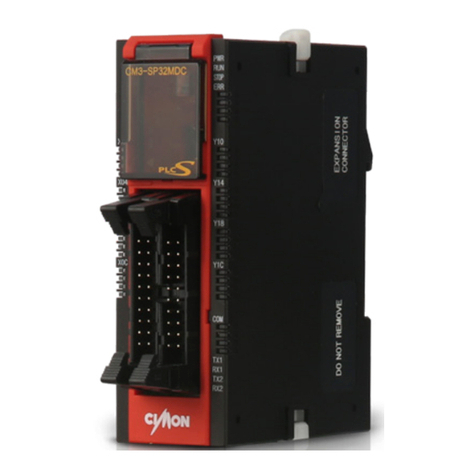
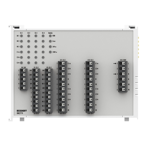
Cimon CM3-SP32PWM User manual


Total Solution for Industrial Automation
Before You Start
This manual contains important information on the use and operation of this device.
Please read all the information carefully for optimal performance and to prevent any
damage or misuse of the device.
Safety symbols are classified into two categories, “WARNING” and “CAUTION”.
Warning This symbol describes situations that could cause major or fatal injury to
the user.
Caution This symbol describes situations that may cause minor injury or damage
to the device.
SAFETY SYMBOLS USED IN THIS PRODUCT MEANS:
This symbol warns the user of potential hazards.
This symbol warns the user of uninsulated voltage within the unit that can cause
dangerous electric shock.
Keep this manual nearby the user operating devices so it can be easily checked.
A-class equipment (Broadcasting communication
equipment for business)
This product has passed the testing for electromagnetic waves for business use, and
has not been designed or manufactured to be used as a household item; users are
advised as such.

Total Solution for Industrial Automation
Design Precautions ( Warning)
Please install a safety circuit to protect entire control system in case of an
unexpected power shut-down and PLC module malfunction. Such anomalies may
severely compromise the integrity of the overall system.
External to the PLC, please install circuits and switches to safeguard the system from
mechanical damages (ex. Emergency stop, upper/lower limit switches,
forward/reverse direction interlocking circuits, etc)
When the PLC detects either of the following failure conditions, it may stop
operation and turn off all outputs.
-The overcurrent protection or overvoltage protection of the power supply
module is activated.
-The PLC CPU detected a failure, such as the watchdog timer error or module
installation failure, with its self-diagnostic function.
In addition, all outputs may be turned on when there is a failure that the PLC CPU
cannot detect, such as in the relay or TR terminal. Build an extra monitoring circuit
that will monitor any output signal that could cause serious accidents.
A greater than normal current passed through the PLC for an extended period of
time, or a short-circuited load flows in the output module may cause a fire.
Build a circuit that turns on the external power supply after the PLC power supply is
turned on. If the external power supply is turned on first, it could result in output
failure or malfunction.
In order to ensure that the system operates safely, please configure an interlock
circuit in the scan program for the following situations.
-When exchanging data with computer or other devices.
-When operated by a computer or other devices.
Not doing so could result in output failure or malfunction.
Precautions for design ( Caution)
Do not bundle the input/output signal or communications cables with the main
circuit and power cables. They should be installed at least more than 100 mm
(3.94inches) apart. Not doing so could result in output failure or malfunction.

Total Solution for Industrial Automation
Precautions for mounting ( Caution)
Use the PLC in the environment that meets the general specifications given in this
manual. Using this PLC in any environment outside the range of the general
specifications could result in electric shock, fire, malfunction, or damage to or
deterioration of the product.
Please ensure that each module is installed correctly in its place. Loosely or
incorrectly installed pieces may result in malfunction, failure, or free-fall.
Power supply in PLC should be turned off before mounting the module. Not doing
so could cause an electric shock or damage to the device.
Install I/O devices or extension connectors correctly. If they are installed incorrectly, it
may result in an input or output failure.
Do not convey direct vibration into PLC. Not doing so could cause electric shock, fire
or malfunctions.
After wiring work, please make sure to close the terminal cover before turning on
the power for the PLC system.
Precautions for wiring ( Warning)
Make sure to check the device’s rated voltage and circuit arrangement before wiring.
Failure to do so may cause electric shock or damage on the device.
Make sure to close the terminal cover before turning on the power of PLC system
after wiring work. Failure to do so may cause electric shock.
Precautions for wiring ( Caution)
Make sure to check device’s regular voltage and sequence of terminals. Failure to do
so may cause fire, electric shock and malfunctions.
Make sure to tighten the screw with standard torque. Loose connections may cause
short, fire or malfunctions.
In grounding the FG ground terminals, be sure to conduct the product at least D
type (Class 3) grounding. Not doing so could result in electric shock or malfunctions.
When wiring, make sure that wiring debris do not enter the module. Failure to do so
may cause fire, equipment damage or malfunctions.

Total Solution for Industrial Automation
Precautions for test run and repair ( Warning)
Please do not touch the terminals when the power is ON. Doing so could cause an
electric shock or malfunctions.
When cleaning or tightening the screw, turn off the power of PLC and all other
systems. Failure to do so could cause an electric shock or malfunctions.
Do not charge, disassemble, heat up, short, or solder the battery. Doing so could
cause the battery to heat up, rupture or ignite thereby harming the user.
Precautions for test run and repair ( Caution)
Do not dissociate the PCB from the module’s casing or make any modifications to
the device. Doing so may cause fire, electric shock or malfunction.
When mounting or separating the module, make sure to turn off power to PLC and
all other devices. Failure to do so could cause an electric shock or malfunctions.
Use radio, walkie-talkie or cellphone devices at least 30cm away from the PLC. Not
doing so could result in malfunction.

Total Solution for Industrial Automation
1
PWM Output Module User’s manual
CONTENTS
1Introduction .................................................................................................. 2
1.1 Features ............................................................................................................................ 4
1.2 Design and Dimensions ..................................................................................................... 5
1.3 Configuring terminal blocks and names............................................................................. 6
2Specification ................................................................................................. 7
2.1 General specification ......................................................................................................... 7
2.2 I/O Specification ................................................................................................................ 8
3Data Memory ................................................................................................ 9
3.1 I/O Memory....................................................................................................................... 9
3.1.1 Output area................................................................................................................... 9
3.2 Buffer Memory................................................................................................................ 11
4Functions .................................................................................................... 13
4.1 Enable of PWM output (Buffer Memory Offset 0)............................................................ 14
4.2 Controlling frequency (Buffer Memory Offset 1 ~ 3)........................................................ 15
4.3 Controlling duty cycle (PWM) (Buffer Memory Offset 10 ~ 21) ........................................ 16
4.4 Ramp control .................................................................................................................. 16
4.4.1 Frequency ramp control (Buffer memory Offset 5 ~ 7) ................................................. 17
4.4.2 Duty cycle ramp control (Buffer memory Offset 30 ~ 41) ............................................. 18
5Operating the PWM Output Module............................................................. 19
5.1 Example for basic operation ............................................................................................ 19
5.2 Practical Examples ........................................................................................................... 21
6Maintenance work and repair....................................................................... 26
6.1 Maintenance work .......................................................................................................... 26
6.2 Repair ............................................................................................................................. 27
6.3 Trouble shooting ............................................................................................................. 28
Appendix 1 Using FROM∙FROMP/TO∙TOP Instructions.......................................... 29
Appendix 2 Method of Address Allocation .......................................................... 35
INDEX............................................................................................................... 43

Total Solution for Industrial Automation
2
CH 1. Introduction
1Introduction
This manual will guide the reader through installation, functions, safety use and
operation of the PWM output module (CM3-SP32PWM) of the PLC-S. This manual
will need to be read and understood before attempting to install or use the device.
Store this manual in a noticeable place so that you can take it out and read it
whenever necessary. Contents of this manual is as below:
Chapter 1 discusses the overview of the manual and introduces important
features of the product.
Chapter 2 explains the general and performance specifications of the product.
Chapter 3 explains the types and features of the data memory stored in the
product.
Chapter 4 goes over the capacities of the product, and how to control the
system.
Chapter 5 guides the user through programming examples of the product.
Chapter 6 explains repair and maintenance methods, and how to operate the
device safely.
In order to run the device properly, the following specifications are required.
Product
Version
Software(CICON)
V6.20 or above is recommended
PLC-S CPU
V6.13 or above is recommended
Below is an instruction on how to check the latest version of the software and CPU.
Run the CICON and click the [Help] –[About CICON information] located in the
upper right side of a menu bar. You can check the version of software in the dialog
box.
[Figure 1] Route to check software version

Total Solution for Industrial Automation
3
PWM Output Module User’s manual
Run the CICON and make a connection with PLC. Click the [Online] –[About PLC
information] or the icon below. You can check the version of CPU firmware in the
dialog box.
[Figure 2] Route to check CPU firmware

Total Solution for Industrial Automation
4
CH 1. Introduction
1.1 Features
PWM (Pulse-Width Modulation) is a digital output that can be used as an analog
output by controlling the duty cycle that contains a certain frequency.
CIMON PWM Output Module has a pulse output function added onto the general
digital output, so it has the same specifications as a CM3-SP32EOC when used as a
general digital output. The module:
Provides general digital outputs up to 32 points.
Supports for PWM pulse outputs up to 12 channels.
The PWM Output Module supports configurable functions such as controlling
frequencies and duty cycles. You can control 4 channels as a group with one
frequency, for a total of 3 groups.
Programming of the PWM pulse frequency can be done up to 4000pps, and the
duty cycle of the output pulse range can be adjusted from 0.0% to 100.0%, in
1/1000 resolution.
Moreover, duty cycle can be controlled individually by each channel, for up to and
total of 12 duty cycles are able to be controlled individually. In addition, the product
supports the ramp control on the frequency and duty cycle.
<Summary>
Programmable duty cycle of output pulse range is from 0.0% to 100.0%, in
1/1000 resolution.
The maximum programmable PWM pulse frequency is 4000pps.
Frequencies can be controlled in group with 4 channels as a unit, for a total of
3 groups.
A total of 12 duty cycles are able to be controlled individually.
The PWM device supports ramp control on frequency and duty cycle.

Total Solution for Industrial Automation
5
PWM Output Module User’s manual
1.2 Design and Dimensions
[Figure 3] PWM module appearance

Total Solution for Industrial Automation
6
CH 1. Introduction
1.3 Configuring terminal blocks and names
[Figure 4] Arrangement of terminals and its notations
For long cables, there is a
potential for unintended
distortion of the PWM pulse.
Therefore, 1.0M cable is
strongly recommended.
Each DC12/24V and DC
GND are connected to the
corresponding terminal
internally.

Total Solution for Industrial Automation
7
PWM Output Module User’s manual
2Specification
2.1 General specification
[Table 1] General specification of PWM module
Items
Specification
Standards
Operating
Temperature
-10 ~ 55 ℃(14 ~ 131℉)
Preserving
Temperature
-25 ~ 80 ℃ (-13 ~ 176℉)
Operating
Humidity
Relative Humidity 5 ~ 95%, Avoid condensation
Preserving
Humidity
Relative Humidity 5 ~ 95%, Avoid condensation
Inner Vibration
Frequency (Hz)
Continual Vibration
Intermittent Vibration
Number
IEC61131-2
Acceleration
(㎨)
Amplitude
(mm)
Acceleration
(㎨)
Amplitude
(mm)
10 ≤ f < 57
57 ≤ f ≤150Hz
4.9 {0.5G}
0.035
9.8 {1G}
0.075
10 times
for each
direction
X, Y, Z
Inner Impact
Maximum impact acceleration : 147 ㎨(15G)
Impression time : 11ms
Pulse wave : a sine half-wave pulse (3 times for each direction ±X, ±Y, ±Z, total on 3
times)
IEC61131-2
Inner Noise
Square wave impulse
noise
±2kV(10 minutes)
CIMON Internal
Test Standard
Electromagnetism
discharge
Voltage : 4kV(Contact Discharge)
IEC61131-2
IEC61000-4-2
Radiation EMF Noise
27 ~ 500 MHz 10V/m
IEC61131-2
IEC61000-4-3
FAST transient burst
Noise
Power supply Module
2kV
IEC61131-2
IEC61000-4-4
Digital input output (≥24V)
1kV
Digital input output (<24V)
0.25kV
Analog input output
Communication interface
Ambient
Conditions
Avoid Corrosive gas and dusts
Operating
Altitude
≤2000m
IEC61131-2
Pollution level
≤2
IEC61131-2
Colling System
Air natural cooled

Total Solution for Industrial Automation
8
CH 2. Specification
2.2 I/O Specification
Types
Specifications of item
Rated input/output voltage
DC 12V ~ 24V
Response time
≤1ms
Operating indicator
LED lighting when the power ON
Insulation for anticorrosion
Photocoupler
Input method
-
Output method
Source
External connection circuit
Internal circuit
[Table 2] I/O Specification of PWM module

Total Solution for Industrial Automation
9
PWM Output Module User’s manual
3Data Memory
Data memory is largely classified into two categories: I/O memory and buffer
memory. I/O memory exchanges I/O data with the CPU through the X and Y area.
Buffer memory exchanges user data with data areas in CPU module using FROM∙
FROMP/TO∙TOP instruction.
[Figure 5] Data exchange between PWM module and CPU
3.1 I/O Memory
I/O memory is an input/output memory area which is provided by the module. This
area can be operated in the scan program. The addresses of the X and Y are
determined by the location where the module is mounted. Please refer to Appendix
2 for details. PWM output module can offer 32-pin output through the I/O memory
area. Please refer to the table in 3.1.1 to check for more details of each point.
3.1.1 Output area
An output area of digital output module outputs the value of data received from the
CPU.
•External indicator: LED (a LED per channel)
•32 Y points (Yn0 ~ Y(n+1)F) (‘n’ states a number that can be decided by
mounted in slots.

Total Solution for Industrial Automation
10
CH 3. Data Memory
Signal Direction : CPU →PWM Output Module
Input
Signal Name
Output
Signal Name
Y20
General output
Y30
General output
Y21
General output
Y31
General output
Y22
Frequency A, CH1, PWM output
(or a general output)
Y32
Frequency C, CH9, PWM output
(or a general output)
Y23
Frequency A, CH2, PWM output
(or a general output)
Y33
Frequency C, CH10, PWM output
(or a general output)
Y24
General output
Y34
Frequency C, CH11, PWM output
(or a general output)
Y25
General output
Y35
Frequency C, CH12, PWM output
(or a general output)
Y26
Frequency A, CH3, PWM output
(or a general output)
Y36
General output
Y27
Frequency A, CH4, PWM output
(or a general output)
Y37
General output
Y28
General output
Y38
General output
Y29
General output
Y39
General output
Y2A
Frequency B, CH5, PWM output
(or a general output)
Y3A
General output
Y2B
Frequency B, CH6, PWM output
(or a general output)
Y3B
General output
Y2C
Frequency B, CH7, PWM output
(or a general output)
Y3C
General output
Y2D
Frequency B, CH8, PWM output
(or a general output)
Y3D
General output
Y2E
General output
Y3E
General output
Y2F
General output
Y3F
General output
[Table 3] Usage of each point of PWM module
※Stated points will follow the table above it the device is mounted in the first
slot.
※All points can be used to emit as general output. The PWM output could only
be operated as the points where it says ‘PWM output’.

Total Solution for Industrial Automation
11
PWM Output Module User’s manual
3.2 Buffer Memory
The PWM output module is equipped with shared memories inside to exchange the
data with CPU. One of these is called buffer memory, which is a collection of word
(16Bit)-unit data. This buffer memory is readable and configurable on scan program,
using FROM∙FROMP/TO∙TOP instructions. Please refer to the Appendix 1 to get
information about FROM∙FROMP/TO∙TOP instructions.
The PWM output module offers 64words of buffer memory in total. Following table
shows the meaning and usage of each data.
OFFSET
Item
Set-up value
parameter
Initial
value
Access
0
PWM output Enable
BIT #0~#11
(Total 12
channels)
0
R/W
1
CH1,2,3,4 Frequency
0~4000(pps)
0
R/W
2
CH5,6,7,8 Frequency
0~4000
0
R/W
3
CH9,10,11,12 Frequency
0~4000
0
R/W
4
Available Later
5
CH1,2,3,4 Frequency ramp control time(x10ms)
Ex) When Frequency ramp control time is set to 100,
100 x 10ms = 1,000ms (1sec)
0~65535
(x 10ms)
0
R/W
6
CH5,6,7,8 Frequency ramp control time(x10ms)
0~65535
0
R/W
7
CH9,10,11,12 Frequency ramp control time(x10ms)
0~65535
0
R/W
8
Available Later
9
Available Later
10
CH1 duty cycle ratio
Ex) When duty cycle ratio is set to 100, 100 x 0.1%
= 10.0%
0~1000
(x 0.1%)
0
R/W
11
CH2 duty cycle ratio
0~1000
0
R/W
12
CH3 duty cycle ratio
0~1000
0
R/W
13
CH4 duty cycle ratio
0~1000
0
R/W
14
CH5 duty cycle ratio
0~1000
0
R/W
15
CH6 duty cycle ratio
0~1000
0
R/W
16
CH7 duty cycle ratio
0~1000
0
R/W
17
CH8 duty cycle ratio
0~1000
0
R/W
18
CH9 duty cycle ratio
0~1000
0
R/W
19
CH10 duty cycle ratio
0~1000
0
R/W

Total Solution for Industrial Automation
12
CH 3. Data Memory
OFFSET
Item
Set-up value
parameter
Initial
value
Access
20
CH11 duty cycle ratio
Ex) When duty cycle ratio is set to 100, 100 x 0.1%
= 10.0%
0~1000
(x 0.1%)
0
R/W
21
CH12 duty cycle ratio
0~1000
0
R/W
22
Available Later
30
CH1 duty cycle ramp time(x10ms)
Ex) When Frequency ramp control time is set to 100,
100 x 10ms = 1,000ms (1sec)
0~65535
(x 10ms)
0
R/W
31
CH2 duty cycle ramp time(x10ms)
0~65535
0
R/W
32
CH3 duty cycle ramp time(x10ms)
0~65535
0
R/W
33
CH4 duty cycle ramp time(x10ms)
0~65535
0
R/W
34
CH5 duty cycle ramp time(x10ms)
0~65535
0
R/W
35
CH6 duty cycle ramp time(x10ms)
0~65535
0
R/W
36
CH7 duty cycle ramp time(x10ms)
0~65535
0
R/W
37
CH8 duty cycle ramp time(x10ms)
0~65535
0
R/W
38
CH9 duty cycle ramp time(x10ms)
0~65535
0
R/W
39
CH10 duty cycle ramp time(x10ms)
0~65535
0
R/W
40
CH11 duty cycle ramp time(x10ms)
0~65535
0
R/W
41
CH12 duty cycle ramp time(x10ms)
0~65535
0
R/W
…
Available Later
63
OS Version
0
R
…
Available Later
[Table 4] Usage and meaning of each buffer memory (PWM module)
※R/W represents for the module’s Read/Write accesses from the CPU. (R: Read W:
Write)
※All values in buffer memory will be erased and set to 0 when the power to the
CPU is turned off or stopped.

Total Solution for Industrial Automation
13
PWM Output Module User’s manual
4Functions
PWM (Pulse-Width Modulation) is a digital output that can be used as an analog
output by controlling the duty cycle that contains a certain frequency. Duty cycle is a
ratio of the ON to OFF status in 1 cycle (pulse).
[Figure 6] Definition of PWM output and duty cycle
As illustrated above, the PWM controls the output from minimum to maximum
values by changing the duty cycle of the pulse.
CIMON PWM output module can be either general digital output or PWM output.
The general digital output can be used up to 32-pin points. From these 32-pin
points, a total of 12-pin points support PWM output. Also, you can prevent drastic
change of the frequency and duty cycle by using the ramp control.

Total Solution for Industrial Automation
14
CH 4. Functions
4.1 Enable of PWM output (Buffer Memory Offset 0)
When PWM-capable points’ BIT value is set to 0, it will be possible to use them as
general output points. Similarly, if it is set to 1, it will be operated as PWM output.
The PWM output function can be enabled by using TO instruction in the buffer
memory Offset 0. Please refer to the 3.2 for information about the buffer memory.
[Table 5] Enabled points of PWM output
Example to enable PWM output of CH1, 3, 9 and output the frequency of CH1 to
1000pps and duty cycle to 50.0%.
BIT
15
BIT
14
BIT
13
BIT
12
BIT
11
BIT
10
BIT
9
BIT
8
BIT
7
BIT
6
BIT
5
BIT
4
BIT
3
BIT
2
BIT
1
BIT
0
Buffer
Memory
Offset 0
0
0
0
0
0
0
0
1
0
0
0
0
0
1
0
1
Binary
(H0105)
Disable
CH
12
CH
11
CH
10
CH
9
CH
8
CH
7
CH
6
CH
5
CH
4
CH
3
CH
2
CH
1
Channel
No.
Operates as below when M00 is ON:
a) Enable the PWM output in CH1, CH3, CH9.
b) Set the frequency of CH1 as 1000pps.
c) Set the duty cycle of CH1 as 50.0%.
In case of power reset or CPU stop, enable the PWM output again by using TO
instruction as all value of the buffer memory will be initialized to 0.
BIT
15
BIT
14
BIT
13
BIT
12
BIT
11
BIT
10
BIT
9
BIT
8
BIT
7
BIT
6
BIT
5
BIT
4
BIT
3
BIT
2
BIT
1
BIT
0
Buffer
Memory
Offset 0
Disable
CH
12
CH
11
CH
10
CH
9
CH
8
CH
7
CH
6
CH
5
CH
4
CH
3
CH
2
CH
1
Channel
No.
Example 1: Enable PWM Output
Table of contents
Other Cimon Control Unit manuals
Popular Control Unit manuals by other brands
Flow-Tek
Flow-Tek M1 Series Installation, operation and maintenance manual
Silicon Laboratories
Silicon Laboratories EMBER EM358 series Reference manual
RAKwireless
RAKwireless RAK4200 quick start guide
Digi
Digi ConnectCore 8X Hardware reference manual

Trenz Electronic
Trenz Electronic TE0720 Schematics
Exhausto
Exhausto EBC 10-P Installation & operating manual
