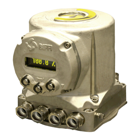
BIFFI ICON3000 Series User manual

Installation, Operation and Maintenance Manual
MDE 256 Rev. 1
April 2021
Biffi ICON3000
Profibus DPV2 Slave Redundancy Module
Copyright © Biffi. The information in this document is subject to change without notice. Updated data sheets can be obtained from our website www.biffi.it or from your nearest Biffi Center:
Biffi Italia s.r.l. - Strada Biffi 165, 29017 Fiorenzuola d'Arda (PC) – Italy PH: +39 0523 944 411 – biffi_italia@biffi.it

Revision Details
Revision Details
April 2021
Installation, Operation and Maintenance Manual
MDE 256 Rev. 1
Revision DetailsRevision Details
Rev. Date Description Prepared Checked Approved
1 April 2021 General update (Migration to new template)
0 December 2016 First release L. P. A. B.

i
Installation, Operation and Maintenance Manual
MDE 256 Rev. 1
Table of Contents
April 2021
Table of Contents
Table of Contents
Section 1: Introduction
Introduction...........................................................................................................1
Section 2: Operation and Storage
Operation and Storage............................................................................................2
Section 3: PRO2000V4_RED Implementation
3.1 Communication Features.............................................................................. 3
3.2 On Board Indication ...................................................................................... 4
Section 4: Profibus DP Description
4.1 RS485 Transmission Mode ............................................................................ 6
Section 5: PRO2000V4_RED Power-Up
PRO2000V4_RED Power-Up.....................................................................................9
Section 6: Slave Redundancy (DP-V2)
6.1 Redundancy Structures............................................................................... 11
Section 7: Wiring: Bus Terminations
Wiring: Bus Terminations.......................................................................................12
Section 8: Master Controller (PLC) Commissioning
8.1 GSD Installing ............................................................................................. 14
8.2 PRO2000V4_RED Interface ......................................................................... 21
Section 9: Local Operator Interface Commissioning
9.1 Bus Control ................................................................................................. 24
9.2 Node Report ............................................................................................... 25
9.3 Bus Signal Failure Indication ........................................................................ 27

ii
Table of Contents
April 2021
Installation, Operation and Maintenance Manual
MDE 256 Rev. 1
Table of Contents
Section 10: Data Exchange Mode (Cyclic Communication)
10.1 Cyclic Communication DPV0....................................................................... 28
10.1.1 Output Data (PLC to Device)........................................................... 28
10.1.2 Input Data (Device to PLC).............................................................. 29
10.2 Acyclic Communication DPV1 (MS2)........................................................... 30
10.2.1 Nameplate ..................................................................................... 30
10.2.2 General Data and Command .......................................................... 31
10.2.3 Maintenance Information for PROFIBUS
Guideline Compliance (Only Read) ................................................. 33
10.2.4 Alarm and Warning Log for PROFIBUS
Guideline Compliance (Only Read) ................................................. 35
10.2.5 Maintenance Commands for PROFIBUS Guideline Compliance ....... 37
10.2.6 Maintenance Information ............................................................... 38
10.2.7 Alarm and Warning Log .................................................................. 39
10.2.8 Maintenance Commands............................................................... 41
Section 11: Diagnosis - Alarms
11.1 Diagnosis Data Blocks ................................................................................. 43
11.1.1 Standard Diagnosis Block ............................................................... 43
11.1.2 Identify Related Block..................................................................... 45
11.1.3 Actuator Specific Diagnostic Alarm................................................. 46
11.1.4 Extended Diagnosis: RedCom Status Message ................................ 48
11.2 Acyclic Communication DPV1..................................................................... 50
11.2.1 Nameplate ..................................................................................... 50
11.2.2 General Data .................................................................................. 51
11.2.3 Maintenance Information ............................................................... 51
11.2.4 Alarm and Warning Log .................................................................. 53
11.2.5 Maintenance Commands................................................................ 54
Appendix A: GSD file
GSD file..................................................................................................................55
Appendix B: Diagnosis: Card information from PLC
Diagnosis: Card information from PLC....................................................................61
Appendix C: Note for Base Card FW 7.00
Note for Base Card FW 7.00...................................................................................63
Appendix D: References
References.............................................................................................................64
Appendix E: PNO Certificate
PNO Certificate......................................................................................................65

Installation, Operation and Maintenance Manual
MDE 256 Rev. 1 April 2021
Introduction 1
Section 1: Introduction
The PRO2000v4_RED is a double electronic card that allows connecting the Biffi electrical actuator
ICON3000 actuators to a PROFIBUS DP network. The cards have their microprocessors and a program
stored internally control them, it works as a pure bus interface and does not affect the actuator
control integrity. It is installed inside the actuator housing and takes the electrical power from the
actuator power supply card. The RS485 interface is located on the card board. The PROFIBUS network
is fully isolated from the actuator electronics.
The PRO2000v4_RED is designed to support PROFIBUS redundant communication as per Slave
Redundancy Specification PNO Order No: 2.212.

April 2021
Installation, Operation and Maintenance Manual
MDE 256 Rev. 1
Operation and Storage
2
Section 2: Operation and Storage
The card is designed to work and to be stored in the same environment of the actuator.

Installation, Operation and Maintenance Manual
MDE 256 Rev. 1 April 2021
PRO2000V4_RED Implementation 3
Section 3: PRO2000V4_RED Implementation
The card consists in a double PCB that is installed inside the actuator housing. It is connected to the
ICON3000 actuators base card via strip connector. The internal wiring connects the PROFIBUS data
lines to the actuator terminal board.
3.1 Communication Features
Communication protocol : PROFIBUS DP according to EN 50170
Network topology : Line (bus) structure. With repeaters tree structures
can also be realized
Transmission medium : Twisted, screened copper cable according to EN 50170
Data rate : 9.6 19.2 45.45 93.75 187.5 500 1500 Kbit/second
Cable length without repeater : 1,200 1,200 1,200 1,200 1,000 400 200 m
Station type : DPV1 and DPV2 (redundancy) slave
Device number : 32 devices per segment without repeater
(max 126, with repeaters)
Bus access : Token-passing between masters and polling for slaves
Electrical power : Actuator powered (as option: auxiliary external voltage supply)
Bus termination : Configurable on board via local operator interface of actuator
Temperature : -40 °C, +85 °C
Fieldbus redundancy : Two independent communication interfaces
EMC protections : EN 50081-2 and EN 50082-2
Types of operation : Cyclic data exchange, Sync mode, Freeze mode, Fail safe mode
Baud rate : Automatic recognition
Addressing : Configurable via local operator interface

April 2021
Installation, Operation and Maintenance Manual
MDE 256 Rev. 1
PRO2000V4_RED Implementation
3.2 On Board Indication
Figure 1
4
Section 3: PRO2000V4_RED Implementation
Slave Board #1
Slave Board #2
LED DL1
LED DL2
LED DL3
Jumper J2
LED DL6
LED DL5
LED DL4
Five LEDs are mounted on the PRO2000v4_RED to give the following indications for Field service.
LEDs indications are active only when jumper JP2 is closed.
DL1 (Red) Data Area Empty: ON when Data Area on interface card is not yet loaded.
BLINK when Data Area is being read from base card.
OFF when Data Area is completely loaded.
DL2 (Red) Base comm: ON when the communication between the base card
and the interface is not working properly.
OFF when the communication between the base card
and the interface is correct.
DL3 (Orange) Slave State: ON when the interface acts as an Primary Slave (i.e. it is the
interface with a valid communication with the Master).
BLINK when the interface acts as a Backup Slave and it is ready
(only for redundant configuration).
OFF when the interface is not communicating with any Master.
DL4 (Green) Termination: ON when the on bard PROFIBUS termination has been inserted.
OFF when the on bard PROFIBUS termination has not been inserted.
DL5 (Green) PROFIBUS: ON when PROFIBUS communication has been established and the
interface has entered in DATA_EX state.
DL6 (Green) Power: ON when the interface is correctly powered.
More indications are given on local operator interface as described in Section 9.2 Node Report.

Installation, Operation and Maintenance Manual
MDE 256 Rev. 1 April 2021
Probus DP Description 5
Section 4: Profibus DP Description
PROFIBUS is a vendor-independent, open field bus standard used in a wide range of application
in process automation. Vendor independence and openness are ensured by the international
standards EN 50170 and EN 50254. The DP communication profile is designed for data exchange at
the field level. The central controllers (as PLC) communicate via serial connection with field devices
(as sensors and actuators). Data exchange is mainly cyclic. The central controller (called Master)
cyclically reads the input information from the field devices (called Slaves) and cyclically writes the
output information to the slaves. In addition, PROFIBUS DP provides communication services for
parameterization, alarm handling, and monitoring of intelligent field devices. The maximum number
of Master and Slave devices in a bus segment is 32 without repeaters. With repeaters the number can
be extended to 126. The maximum cable length depends on the speed of transmission. Higher is the
speed shorter is the length. For instance, with baud rate 93.75 Kb/second, the maximum cable length
is 1,200 m without repeaters.
Mono-master or multi-master system configuration can be provided. Bus access is controlled by token
passing procedure between masters and master-slave procedure (polling) between master and slaves.
Types of devices:
DP Master Class 1 (DPM 1): This is the central controller that cyclically exchange information
with the field devices. Typical devices are PLC or PC.
DP Master Class 2 (DPM 2): These devices are necessary for commissioning, maintenance
and diagnostics.
Slave: Field device such transmitters, actuators, drives, etc.
The Figure below shows a PROFIBUS DP configuration with two Master devices and different Slave devices.
Figure 2
ICON3000 Actuators
Logical token ring between master devices
Master
devices
Slave devices
General Drive Transmitter
PLC PC

April 2021
Installation, Operation and Maintenance Manual
MDE 256 Rev. 1
Probus DP Description6
Section 4: Profibus DP Description
4.1 RS485 Transmission Mode
The PRO2000v4_RED module uses a half-duplex, multidrop, serial communication line RS485.
The card communicates with the Masters via its RS485 interface and the transmission media consists
in a shielded twisted pair cable. Transmission speed from 9.6 kbit/seconds to 1.5 Mbit/seconds are
available. One unique transmission speed is allowed for all devices on the bus when the system works.
All devices are connected in a bus structure. Up to 32 station (Master and Slaves) can be connected
in one segment without repeaters. Repeaters can be used to extend the number of device up to 126
and to enlarge the network area. The following Table shows the relationship between baud rate and
segment length.
Table 1.
The bus must be terminated by an active bus terminator at the beginning and at the end of each
segment. Only two terminations in one bus segment must be provided. To ensure error-free
operation, both bus terminators must be powered. The maximum cable length depends on the
transmission speed. Cable lengths indicated in Table 1 are based on type A cable, as specified by the
EN 50170, having the following characteristics.
• Impedance from 135 to 165 ohm
• Capacity < 30 pF/m
• Loop resistance 110 ohm/km
• Wire gauge 0.64 mm
• Conductor area > 0.34 mm2
The use of cable of previously used type B is not recommended.
The data lines must not be reversed. Use of shielded cable is mandatory for having high system
immunity against electromagnetic disturbs. The shield should be connected to ground on both
sides. The data lines should be kept separate from all other cables. It should be laid in separate,
conductive and earthed cable trunking. It must be ensured that there are not voltage differences
between individual nodes of PROFIBUS DP.
Baud Rate Maximum segment length (no repeater)
9.6 K 1,200 m
19.2 K 1,200 m
45.45 K 1,200 m
93.75 K 1,000 m
187.5 K 1,000 m
500 K 400 m
1500 K 200 m

Installation, Operation and Maintenance Manual
MDE 256 Rev. 1 April 2021
Probus DP Description 7
Section 4: Profibus DP Description
DEVICE 1 DEVICE 2
CABLE BUS TERMINATION
shielding
Figure 3
The Figure below shows the bus with an actuator at the end of the bus segment. To be sure that the
terminations are supplied also if the mains fails, an auxiliary voltage supply generated by an UPS is
connected to the actuator to supply the electronics and the termination.
Figure 4
PLC
MAINS MAINS
Term. OFF Term. OFFTerm. ON
MAINS + 18-32 V AC/DC
from UPS
BUS cable
Term. ON
VP (5 V DC)
Data line
Data line

April 2021
Installation, Operation and Maintenance Manual
MDE 256 Rev. 1
PRO2000V4_Red Power-Up8
Section 5: PRO2000V4_Red Power-Up
Section 5: PRO2000V4_RED Power-Up
On power-up the card checks the baud rate and then it waits for the “parameterization” telegram
from the Master. The parameterization message contains user information needed for actuator
operation and listed in the Section 10: Data Exchange Mode (Cyclic Communication).
After that the card waits for the “configuration” telegram from Master. The configuration message
contains the number of input and output bytes reserved in the memory of the Master device for each
slave. Only the number of bytes determined in the configuration is transmitted between Master and
Slave. This information is called “module”.
When parameters and configuration are correct, the module enters in “Data exchange mode” and
starts with normal operation. The Master cyclically sends commands to the Slave and read its status.
The following Figure shows the state machine of a DP slave:
Figure 5
Wait
parameterization
Wait
configuration
Data exchange
mode
Set Slave address
Check parameters
Parameterization correct
Check configuration
Configuration not OK
Slave Fault
Configuration correct
Cyclic data exchange
Power on

Installation, Operation and Maintenance Manual
MDE 256 Rev. 1 April 2021
Slave Redundancy (DP-V2) 9
Section 6: Slave Redundancy (DP-V2)
MASTER
PROFIBUS PROFIBUS
Redundancy
extensions
Process data
Primary slave
Redundancy
extensions
Backup slave
Redundancy slave
Section 6: Slave Redundancy (DP-V2)
The PRO2000v4_RED is designed to allow the actuator to act as a redundant slave in accordance to
PNO Order No: 2.212.
A slave redundancy architecture has high reliability thanks to important features:
• No loss of data during fault
• Short switch over time
A redundant slave foreseen two Profibus communication interfaces with special redundancy
extensions and a redundancy communication channel.
A redundant slave must foresee:
• At least 2 PROFIBUS connections
• 2 independent PROFIBUS communication interfaces
• A redundancy communication channel (RedCom)
The RedCom provide a PROFIBUS independent communication between the two slave interface
cards. The RedCom channel performance capability influences the total switch over time of the
redundant slave.
The following Figure shown an overview of the system architecture.
Figure 6

April 2021
Installation, Operation and Maintenance Manual
MDE 256 Rev. 1
Slave Redundancy (DP-V2)10
Section 6: Slave Redundancy (DP-V2)
PROFIBUS
PROFIBUS
RS485
Transceiver
PROFIBUS
ASIC
microcontroller
Red extensions
Internal comm.
channel
Internal comm.
channel
Actuator
base card
PROFIBUS
RS485
Transceiver
PROFIBUS
ASIC
microcontroller
Red extensions
Internal comm.
channel
Internal comm.
channel
The PROFIBUS DP communication with a redundant slave will be done in the following way:
• MS0 (cyclic): The primary slave uses the cyclic communication to send and receive the
process values. In addition, the primary slave sends all diagnosis information about itself
and the backup slave.
The backup slave also sends and receives data with the MS0 services, but these data is not
relevant and shall be ignored by the backup slave and the master.
• MS1 (acyclic): Only the primary slave receives and transmits MS1 services.
When the backup slave receives a MS1 service, it responds negative.
• MS2 (acyclic): Both the primary and the backup slave receive acyclic MS2 services.
Both slave interface cards process these services to allow an individual communication with
the specific device.
At the start up (and every time it is necessary), the Master sends the PRM commands to two slave
interface cards in order to determine which is the Primary and the Backup.
The Primary slave sends the complete diagnosis information of the Redundant slave.
The monitoring of the PROFIBUS communication ability of the Redundant slave is done by the
redundancy of the master with standard PROFIBUS mechanisms. Therefore, also all communication
parts of the Backup slave shall be fully operable. They shall be connected to the bus, the driver shall
be enabled, and the PROFIBUS ASIC is initialized and running.
If the master redundancy detects a communication failure to the Primary slave, it will issue a
command to the Redundant slave to inform it about that fact. The Redundant slave performs a
redundancy switchover.
The monitoring of the PROFIBUS communication by the master will work also for a single line failure.
That means, when only the receive-line or the transmit-line of the Primary slave has a failure, the
Master will also detect this and the command will be sent to the Redundant slave.
One of the key features of the Slave redundancy is that the process input and output signals are stable
during a redundancy switchover. From the process point of view, a redundancy switchover is invisible.
The master or the master application is responsible to keep the input signals of a Redundant slave
stable during the switchover.
The hardware implementation of the Slave Redundancy for the PROFI2000v4 is shown in the
Figure below:
Figure 7

Installation, Operation and Maintenance Manual
MDE 256 Rev. 1 April 2021
Slave Redundancy (DP-V2) 11
Section 6: Slave Redundancy (DP-V2)
6.1 Redundancy Structures
The Slave redundancy specification (Order No. 2.212) foreseen two different type of redundancy
architectures: the System redundancy and the Flying redundancy.
Figure 8 System Redundancy
In the System redundancy layout, the two interfaces may have the same address because the two
interfaces are on different channels.
A synchronization method must be active between the Master stations to take the information from
the Primary Slave.
Figure 9 Flying redundancy
In the Flying redundancy layout, the two interfaces shall have different addresses because the two
interfaces are on the same channel.
The backup address shall be PRIMARY ADDRESS+64.
Backup
Master
Primary
Master
Channel 2 Channel 1
Backup
Master
Primary
Master

April 2021
Installation, Operation and Maintenance Manual
MDE 256 Rev. 1
Wiring: Bus Terminations12
Section 7: Wiring: Bus Terminations
The very flexible redundancy strategy implemented in the PRO2000v4_RED card allows also different
layout that the Master station can drive.
The bus terminations can be switched on each data lines by means of two links, configurable via local
operator interface.
The Figure below shows the wiring necessary in case of redundant slave. The termination must be
linked to the data lines only if the actuator is at the beginning or at the end of the bus segment.
Figure 10
bus out bus in
Data line -
Data line -
Data line +
Data line +
bus out
Shield
Shield
Terminal
board
bus in
Termination
control
Termination
control
ICON-F01
card #1
ICON-F01
card #2
bus out bus in
PROFIBUS
RS485
transceiver
PROFIBUS
RS485
transceiver

Installation, Operation and Maintenance Manual
MDE 256 Rev. 1 April 2021
Wiring: Bus Terminations 13
Section 7: Wiring: Bus Terminations
The PRO2000v4_RED card takes its electrical supply from the actuator power supply card.
The RS485 bus transceiver is isolated from the actuator electronics. Also, the voltage supply of the
bus termination is isolated. The PRO2000v4_RED card is equipped with on-board bus termination
that should be used when the actuator is at the beginning or at the end of the bus segment and if
there is no external termination. The bus termination can be switched on the data lines by means of
a link, configurable via local operator interface.
Since the bus termination is a crucial component to ensure error-free operation, it is important that
termination remains powered also when the actuator supply has left. If the internal termination are
used, it is suggested to connect to the actuator also an auxiliary 18/36 V AC/DC generated by safe
source that will supply just the actuator electronics and the PROFIBUS termination.
Hence, in order to avoid Profibus connection loss if the actuator is switched off it must be present an
internal DC/DC converter option not included in the normal supply for the actuator, to be specified
upon purchase order.
NOTICE
For other wiring information see the Wiring diagram of the card.

April 2021
Installation, Operation and Maintenance Manual
MDE 256 Rev. 1
Master Controller (PLC) Commissioning14
Section 8: Master Controller (PLC) Commissioning
Section 8: Master Controller
(PLC) Commissioning
8.1 GSD Installing
A GSD is a readable ASCII text file and contains both general and device-specific specifications for
communications. Each of the entries describes a feature that is supported by a device.
A GSD supports automatic checks for input errors and data consistency.
GSD name: ICO20FD9.gsd
The following pictures shown the steps for the GSD installing for the Hardware configuration
interface in the SIMATIC STEP 7.
NOTICE
For the GSD installation in the SIMATIC STEP 7 Totally Integrated Automation Portal (TIA Portal)
the steps are the same apart that Device & Network configuration interface is used in place of the
Hardware configuration.
All the next folders and filenames can chance following the device installation is ongoing.
• Install the GSD file of the device present in the folder receive from Biffi.
Figure 11

Installation, Operation and Maintenance Manual
MDE 256 Rev. 1 April 2021
Master Controller (PLC) Commissioning 15
Section 8: Master Controller (PLC) Commissioning
Figure 12
Figure 13
Figure 14

April 2021
Installation, Operation and Maintenance Manual
MDE 256 Rev. 1
Master Controller (PLC) Commissioning16
Section 8: Master Controller (PLC) Commissioning
• Then insert the object in the Profibus network.
Figure 15
Other manuals for ICON3000 Series
10
Table of contents
Other BIFFI Control Unit manuals