Cincinnati CL-900 Series Use and care manual

OPERATION, SAFETY, AND MAINTENANCE MANUAL
CL-900 SERIES LASER SYSTEM
5x10, 6x12, 8x20 FRAME
CINCINNATI INCORPORATED
C I N C I N N A T I, OHIO 4 5 2 1 1
EM-573 (N-04-18) COPYRIGHT 2018
CINCINNATI INCORPORATED


MANUAL GUIDE
To get the maximum benet of your new CINCINNATI INCORPORATED machine, read this manual thoroughly
and refer to it often for guidance and information.
IMPORTANT: Before you operate the machine, read and understand thoroughly, Section 3 on Safety.
SIGNAL ICONS
This manual contains important icons that are associated with a signal word like Danger,” or “Warning,” or “Note”.
The icon and/or signal word indicate the severity of the condition or situation. Be sure to read these statements
and take special care to follow the instructions.
SIGNAL WORD DESCRIPTION ICON
DANGER
Means that there is a condition or situation
that will cause death or severe injury if you
do not follow the instructions given.
WARNING
Means that there is a condition or situation
that will cause moderate injury if you do
not follow the instructions given.
CAUTION
Means that minor injury or machine
damage could occur if you do not follow the
instructions given. You may also have to
start a procedure over if you do not follow
the instructions in a caution statement.
IMPORTANT
Means that the text gives additional
information that must be followed for
safety or other signicant reason.
NOTE Means that the text gives additional
information, clarication, or helpful hints.


EM-573 (N-04-18)
CL-900 SERIES CONTENTS
INTRODUCTION
SECTION 1 IDENTIFICATION
SECTION 2 INSTALLATION
LIFTING AND MOVING ..................................................................................2-1
FOUNDATION ................................................................................................2-2
INSTALLATION OF MACHINE .......................................................................2-2
CHILLER ........................................................................................................2-3
LEVELING ......................................................................................................2-3
PRELIMINARY LEVELING .......................................................................2-3
FINAL LEVELING .....................................................................................2-5
ELECTRICAL CONNECTION ........................................................................2-6
SAFETY DEVICES .........................................................................................2-6
SECTION 3 SAFETY
SAFETY IS EVERYONE’S JOB .....................................................................3-1
INTRODUCTION TO LASER SAFETY ....................................................3-1
SAFETY STANDARDS AND PUBLICATIONS ...............................................3-2
LASER HAZARD CLASSIFICATION .............................................................3-3
CONTROL MEASURES .................................................................................3-4
EXPLANATION OF LASER RADIATION........................................................3-5
LASER TYPES .........................................................................................3-5
HAZARDS - CINCINNATI LASER SYSTEMS - FIBER LASER .....................3-6
EYE HAZARDS ........................................................................................3-6
SKIN HAZARDS .......................................................................................3-7
NOMINAL HAZARD ZONES ..........................................................................3-7
BEAM EXPOSURE CATEGORIES ..........................................................3-8
ASSOCIATED HAZARDS ............................................................................3-10
FIRE .......................................................................................................3-10
FUMES AND DUST ................................................................................ 3-11
GAS STORAGE ........................................................................................... 3-11
COMPRESSED GAS CYLINDERS ........................................................ 3-11
CRYOGENIC LIQUID .............................................................................3-13
TRAINING ....................................................................................................3-14
MACHINE HAZARDS AND WARNINGS ......................................................3-15
MOVING MACHINE MEMBERS ............................................................3-15
WARNING (AWARENESS) LIGHTS ......................................................3-15
CUT AREA ENCLOSURE ......................................................................3-15
SAFETY SIGNS ...........................................................................................3-16
SAFETY GUIDELINES .................................................................................3-19
SAFETY MAINTENANCE CHECK ...............................................................3-19
SECTION 4 SPECIFICATIONS
DIMENSIONS .................................................................................................4-1
SPECIFICATIONS ..........................................................................................4-1
PIPING CONNECTIONS ................................................................................4-4
OPTICAL ELEMENTS ....................................................................................4-4
GAS REQUIREMENTS ..................................................................................4-5
AMBIENT TEMPERATURE ............................................................................4-8
CAPACITIES ..................................................................................................4-8
PRINCIPLE OF OPERATION .........................................................................4-8
CONTOURING ACCURACY ..........................................................................4-9
SECTION 5 SETUP AND USE
LOADING MATERIAL .....................................................................................5-1
GAUGING .......................................................................................................5-1
CUTTING Y-AXIS MATERIAL STOPS .....................................................5-1
X AND Y-AXIS SQUARENESS ................................................................5-3
X-AXIS MATERIAL STOPS ......................................................................5-3

EM-573 (N-04-18)
SECTION 6 MACHINE CONTROLS
OPERATOR CONTROL STATION .................................................................6-1
MACHINE OPERATOR PANELS ...................................................................6-2
FRONT PANEL CONTROLS ....................................................................6-2
AXIS MOTION CONTROLS .....................................................................6-3
PALLET CONTROLS ...............................................................................6-4
REMOTE STATION ........................................................................................6-7
LOAD FRAME EMERGENCY STOP .............................................................6-8
SECTION 7 OPERATION
FOR ADDITIONAL SETUP AND OPERATION INFORMATION FOR THIS
MACHINE, REFER TO EM-574, SECTION 7 - OPERATION, A SUPPLEMENT
TO THE OPERATION MANUAL FOR THE CL-900 LASER SYSTEM. ..........7-1
SECTION 8 OPTIONS
FUME BLOWER .............................................................................................8-1
BALL TRANSFER LOAD STATION ................................................................8-1
CINCINNATI MATERIAL HANDLING SYSTEMS ...........................................8-1
AIR ASSIST GAS FILTER AND DRYER ........................................................8-1
AUTOMATIC NOZZLE CHANGER (ANC) ......................................................8-1
SECTION 9 MAINTENANCE AND ADJUSTMENTS
LUBRICATION REQUIREMENTS ..................................................................9-1
DRIVES LUBRICATION ...........................................................................9-1
Z-AXIS LUBRICATION .............................................................................9-2
FUME SYSTEM LUBRICATION ...............................................................9-2
MATERIAL CLAMP LUBRICATION ..........................................................9-3
MAGNETIC TRACK MAINTENANCE ............................................................9-3
PALLET DRIVE MAINTENANCE ...................................................................9-3
CHAIN DRIVE TENSION ADJUSTMENT ...............................................9-3
SCRAP REMOVAL ...................................................................................9-4
PALLET GUIDE RAILS ...................................................................................9-5
ENCODER MAINTENANCE ..........................................................................9-5
ENCODER CLEANING ............................................................................9-5
OPTICS HANDLING AND CLEANING ...........................................................9-6
REPLACING THE FOCUS LENS CARTRIDGE.............................................9-7
REPLACING THE LOWER COVER GLASS DRAWER ...............................9-10
REPLACING THE COVER GLASS IN THE DRAWER ................................9-12
AUTO FOCUS CUTTING HEAD ..................................................................9-13
MAINTENANCE .....................................................................................9-13
AUTO FOCUS TROUBLESHOOTING ...................................................9-15
AUTOMATIC NOZZLE CHANGER ...............................................................9-15
AIR DRYER ..................................................................................................9-17
PREVENTIVE MAINTENANCE ....................................................................9-18
DAILY MACHINE INSPECTION .............................................................9-18
WEEKLY MACHINE INSPECTION .......................................................9-18
SEMI-ANNUAL (2000 HOURS) MACHINE INSPECTION .....................9-19
ANNUAL MACHINE INSPECTION ........................................................9-21
SECTION 10 SERVICE AND PARTS
ORDERING REPAIR PARTS ......................................................................10-1
RETURNING PARTS FOR CREDIT .............................................................10-1
SERVICE ......................................................................................................10-1
TECHNICAL TRAINING ...............................................................................10-1
CUSTOMER INFORMATION CENTER .......................................................10-2

INTRODUCTION
CINCINNATI CL-900 SERIES LASER SYSTEM - FIBER LASER
The Fiber Laser System produces two-dimensional contoured shapes from at material by
moving a focused laser beam along a programmed path. The beam comes from a stationary
laser generating unit and is directed to a moving lens by a ber optic cable routed through a
moving gantry. The workpiece remains stationary while a narrow strip of material is removed
along the path made by the lens. Material is removed by vaporization and melting where the lens
concentrates laser power into a small spot on the workpiece. Assist gas is also used to control
the cutting process.
The gantry moves the lens to produce the programmed workpiece geometry. A motion controller
commands servo drives to control the gantry motion. The program provided by the user includes
commands to specify feed rate, laser power, and assist gas.
PART QUALITY
The following factors affect part quality:
• Machine condition
• Operator ability
• Setup and Programming
• Quality and type of material
CINCINNATI machines are designed to be rugged and durable. However, improper adjustment
or lack of maintenance can reduce the quality of parts produced on the machine. The quality
of a laser-cut edge depends on the combination of a uniform laser beam of adequate power,
properly focused on the workpiece with an adequate supply of the correct assist gas, traveling
at a speed compatible with the material removal rate.
Critical manual adjustments are: lens focal point location and lens-to-nozzle centering. The
Auto Focus Cutting Head eliminates manual focal point adjustment.
Part quality depends on the program to command the correct combination of laser power,
assist gas, and feed rate for the material type and thickness being processed. Part accuracy
depends on the program for proper use of kerf width compensation and for selection of feed
rate within radius contouring accuracy limits.
Material quality can affect the repeatability of process parameters. Material with uniform
composition, uniform thickness, and a smooth, clean surface will minimize variations in part
quality.

EM-573 (N-04-18)
1-1 EM-573 (N-04-18)
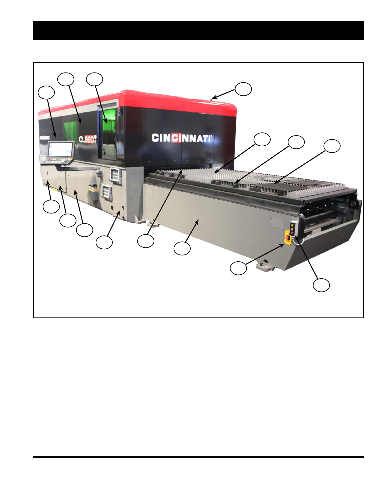
SECTION 1 IDENTIFICATION
CINCINNATI CL-900 SERIES LASER SYSTEM - FIBER LASER
1. ENCLOSURE
2. OPERATOR DOOR
3. LASER STATUS INDICATOR LIGHT
4. MATERIAL SUPPORTS
5. MATERIAL CLAMPS
6. UPPER PALLET
7. BALL TRANSFER REMOTE (OPT)
8. E-STOP BUTTON
9. LOAD FRAME
10. PALLET DOOR
11. SCRAP BIN ACCESS DOOR
12. OPERATOR CONTROL STATION
13. MAIN FRAME
14. CONTROL ENCLOSURE
15. POWER ENCLOSURE
Figure 1-1 Front View
456
1 2 3
7
8
9
10
11
12
13
15
14

1-2
EM-573 (N-04-18)
1. GAS AND WATER CONNECTIONS
2. ENCLOSURE ACCESS
3. ELECTRICAL CONNECTION
4. MAIN DISCONNECT
5. POWER ENCLOSURE
6. CONTROL ENCLOSURE
Figure 1-2 Rear View
12
34
5
6

1-3 EM-573 (N-04-18)
1. LASER STATUS INDICATOR LIGHTS
2. CONTROL KEY
3. FIBER LASER E-STOP
Figure 1-3 nLight Source
3
2
1
1-4
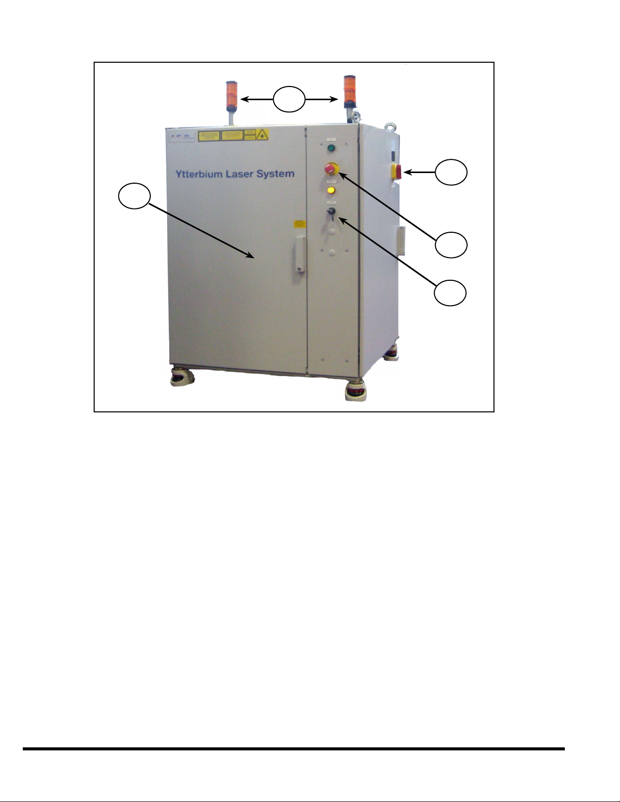
EM-573 (N-04-18)
1. ENCLOSURE
2. LASER STATUS INDICATOR LIGHTS
3. FIBER LASER MAIN DISCONNECT
4. FIBER LASER E-STOP
5. KEYSWITCH
Figure 1-4 IPG Light Source
2
3
4
5
1

1-5 EM-573 (N-04-18)
1. ENCLOSURE
2. STATUS INDICATOR LIGHTS
3. CONTROL SWITCH
4. MAIN DISCONNECT
5. CAREL CONTROLLER
Figure 1-5 Chiller
4
3
1
2
5
1-6
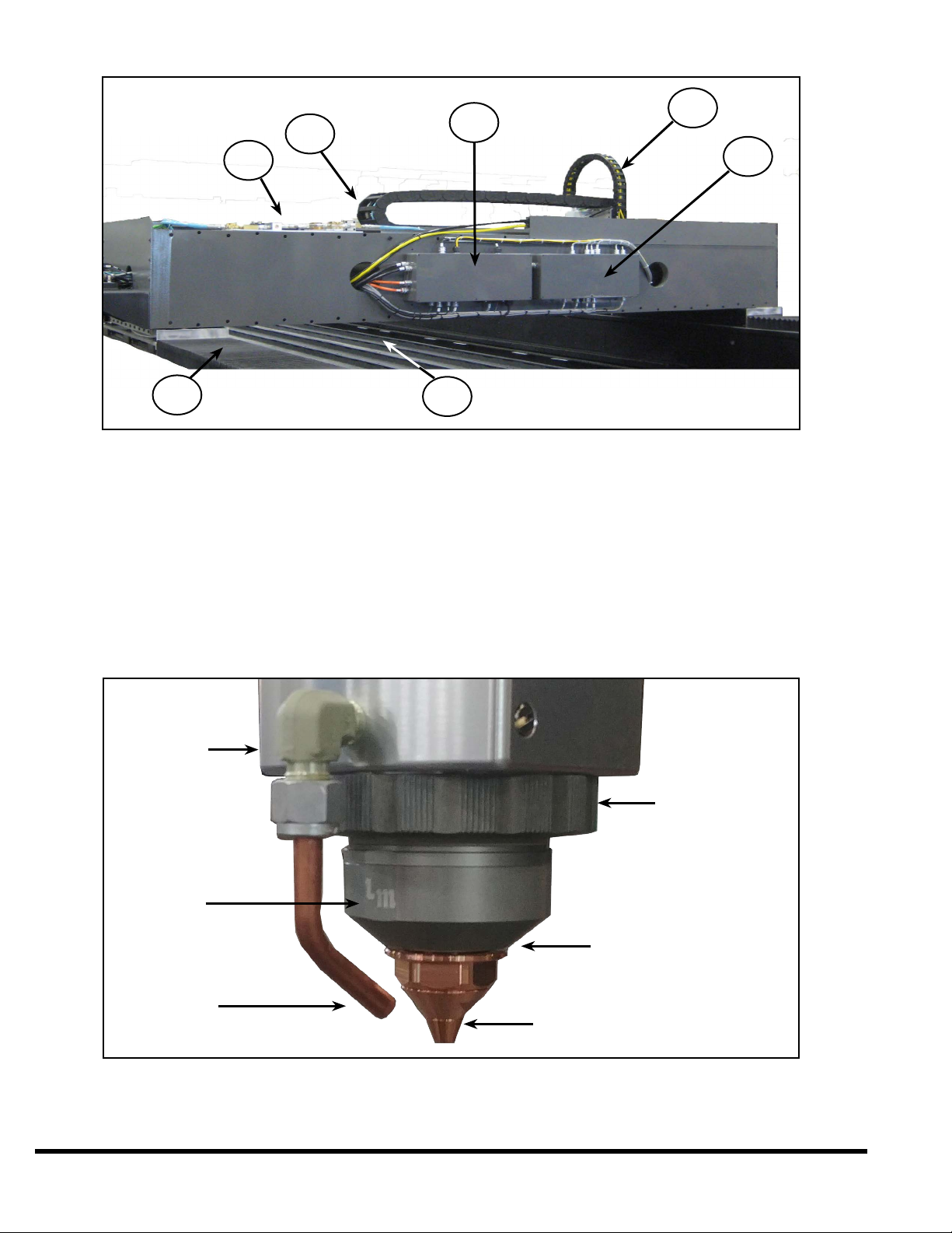
EM-573 (N-04-18)
1. X-2 AXIS WAY COVER
2. ASSIST GAS PROPORTIONAL VALVES
3. Y-AXIS CABLE CARRIER
4. LEFT GANTRY ENCLOSURE
5. Z-AXIS FIBER CABLE CARRIER
6. RIGHT GANTRY ENCLOSURE
7. SCRAP TRAY ASSEMBLY
Figure 1-6 Rear View of the Gantry
Figure 1-7 Complete Tip Assembly
NOZZLE TIP
RAPID PIERCE
AIRBLAST
NOZZLE N
FRONT OF
THE HEAD
TIP ASSEMBLY
NUT
TIP ASSEMBLY
ALIGNMENT
FLAT ON
THE TIP
ASSEMBLY
2345
6
17

1-7 EM-573 (N-04-18)
1. BEAM CENTERING ADJUSTERS
2. AIR BLAST
3. COMPLETE TIP ASSEMBLY
4. Z-AXIS CABLE CARRIER
5. UPPER COVER GLASS DOOR
6. ASSIST GAS HOSE
7. LOWER COVER GLASS DOOR
Figure 1-8 Y-Plate and Auto Focus Head Assembly
1
2
3
4
5
6
7
1-8
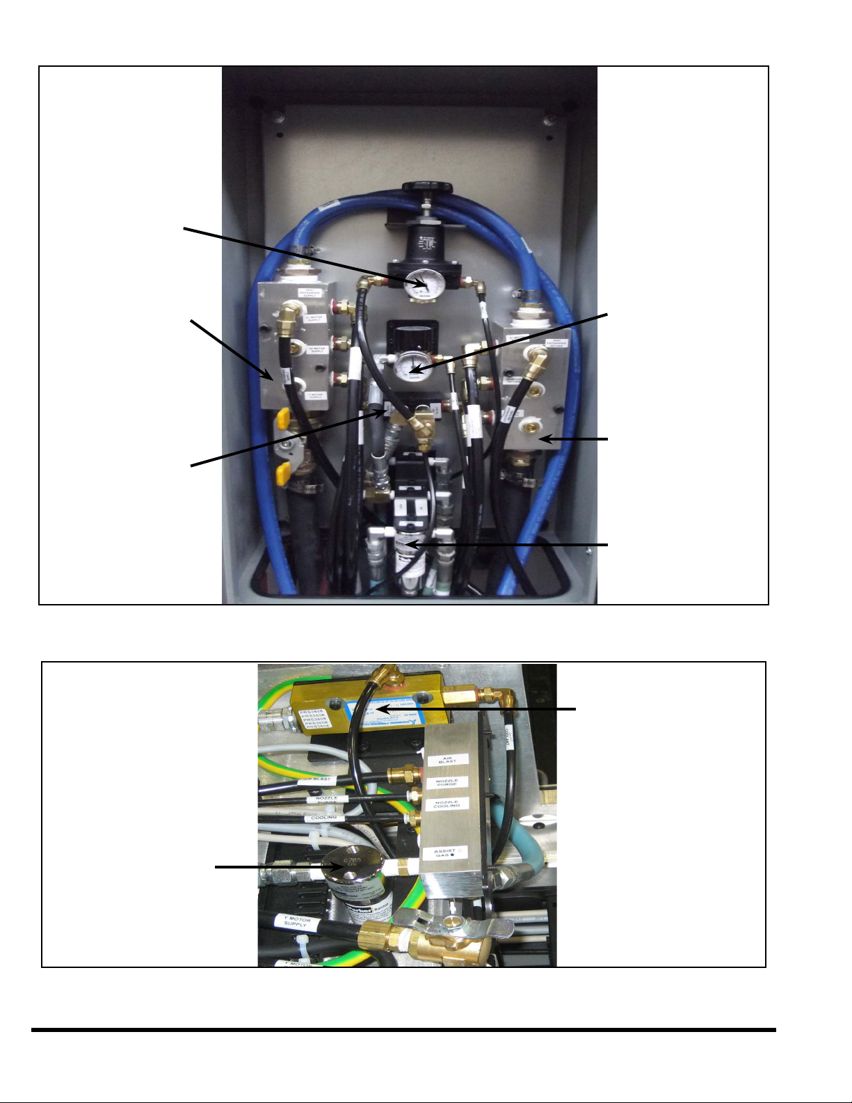
EM-573 (N-04-18)
Figure 1-9 Pneumatic Enclosure
Figure 1-10 Y - Plate Manifold
ASSIST GAS FILTER
LENS COOLANT
SENSOR
PALLET DOOR
REGULATOR
SUPPLY MANIFOLD
AIR SUPPLY
MANIFOLD
N2REGULATOR FOR
OPERATION STATION
RETURN MANIFOLD
ASSIST GAS FILTERS

2-1 EM-573 (N-04-18)
SECTION 2 INSTALLATION
Before Proceeding contact a CINCINNATI Laser Service representative for pre-installation instructions.
LIFTING AND MOVING
Machine weights are provided in Section 4 - SPECIFICATIONS.
The main frame is lifted by using four standard lifting clevises attached to four lifting links (C.I. P/N #920584)
with spacers (C.I. P/N #921838). The four lifting links (supplied by CINCINNATI) are attached to the inside of
the main frame with 1”-8 UNC SHCS bolts. See Figure 2-1.
Figure 2-1 Lifting Main Frame
When lifting with chains, cables, or straps, use the maximum length possible, to reduce the side loading
generated at the lift points. Use spreader bars or intermediate lifting beam if ceiling height will not allow a high
pick.
Before lifting the main frame, be sure that lifting
links (C.I. # 920584) and spacers (C.I. # 921838)
are installed. Do not use eyebolts or other devices
that are not designed for excessive side loads.
Using improper lifting devices could result in
serious injury or death to bystanders and/or
cause extensive damage to the main frame and
ber laser.

2-2
EM-573 (N-04-18)
Extreme care must be taken not to subject the machine to shock loads. The machine must be lifted and
set down gently.
The load frame can be lifted using straps with S-hooks at each of the four outer corners. The S-hooks are
hooked in the access holes located at the bottom of the load frame. Adequate padding must be used at all points
to protect the machine’s nish. The straps can be gathered and lifted with a hook attachment. See Figure 2-2.
Figure 2-2 Lifting Load Frame
FOUNDATION
A Foundation Plan drawing is provided shortly after the machine is ordered. This drawing provides the user with
detailed information required to locate the equipment and the eight machine anchors.
The customer should prepare the eight anchor locations prior to arrival of the equipment. The eight pads must
be pre-leveled to lie in the same plane within .50 inches (12.7 mm), and the anchor holes should be drilled as
specied on the Foundation Plan drawing. CINCINNATI INCORPORATED provides anchors, studs, nuts, and
shims for nal leveling.
If the machine is going to be installed near shock inducing equipment, such as punch presses, turret punches,
etc., contact CINCINNATI INCORPORATED.
INSTALLATION OF THE MACHINE
After setting the machine on the anchor studs, place washers and nuts on studs, but do not tighten. Follow these
steps for proper installation:
1. Remove lifting clevises and spacers.
2. Remove all steel banding and protective wrappings.
3. Install fume fan (optional) and fume duct connecting to fume plenum with ange and fasteners provided.
Seal connection with a bead of RTV silicone. Make the electrical connection to the fan drive motor with
wiring provided.
4. Connect the (customer-furnished) fume exhaust system to the fume duct exit port.
5. Complete preliminary leveling procedure described below.
6. CINCINNATI Service will install the operator control station and complete nal electrical connections to the
control.
7. Install gas lines, wiring, and hoses as described in the pre-installation manual.
2-3 EM-573 (N-04-18)
CHILLER
The water chiller is a free-standing unit requiring only oor support. Cooling lines are connected to the main
frame and laser at the gas and water location mounted to the rear of the machine. Hoses are furnished to
connect the chiller when located as shown on the Foundation Plan. If an alternative chiller location is required,
consult CINCINNATI INCORPORATED. See Section 4 - SPECIFICATIONS for chiller uid specications.
LEVELING
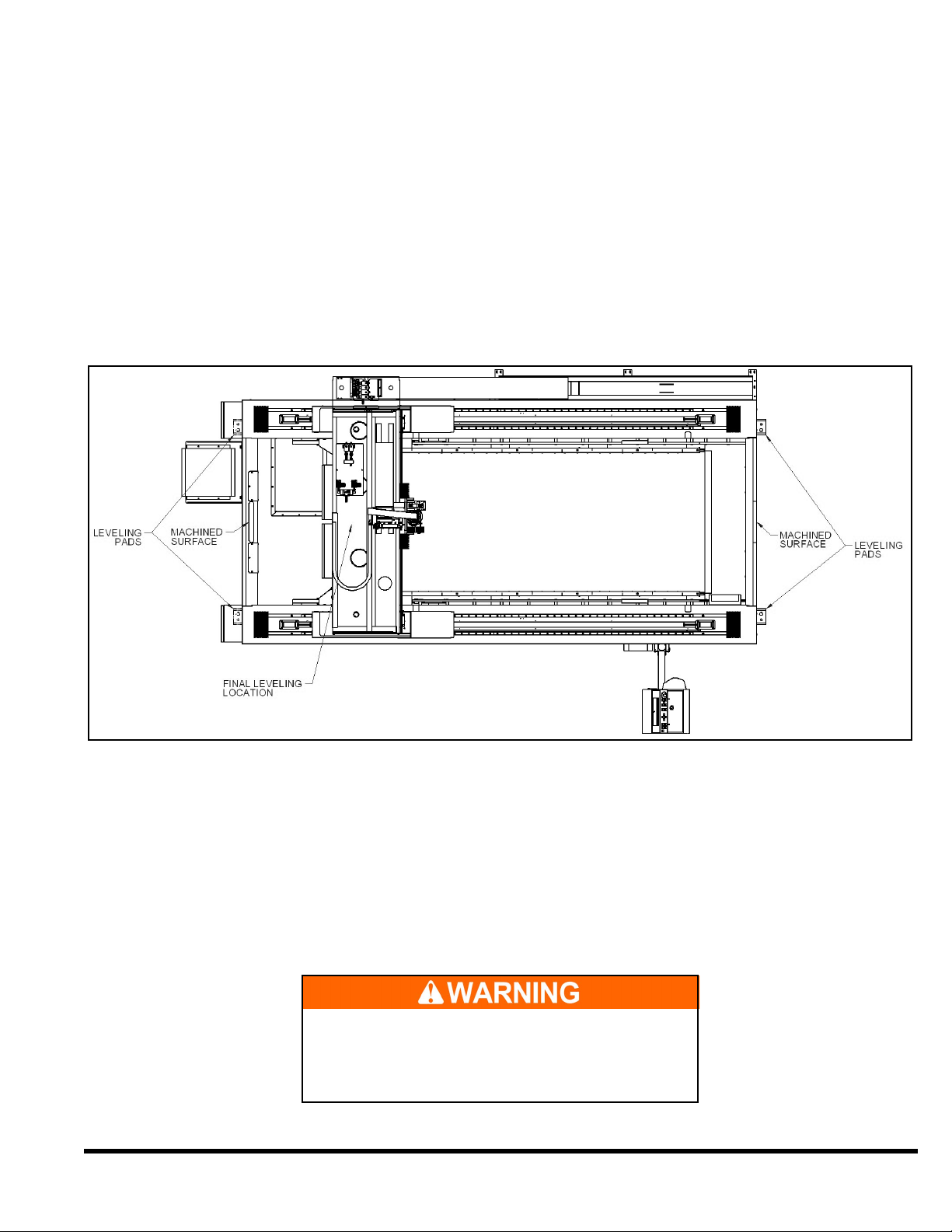
Main frame leveling adjustments are made using jackscrews provided at the mounting pads. Figure 2-3 shows
the mounting pads. The machine foot mounting or leveling pads are located on the outside surface of the main
frame in the four corners. Slotted shims are inserted between the machine foot and steel spacer block as shown
on the Foundation Plan drawing. After shims are inserted, jackscrews are to be backed off or removed. The
procedure for leveling is described in the next sections.
Figure 2-3 Main Frame Leveling Adjustments
PRELIMINARY LEVELING
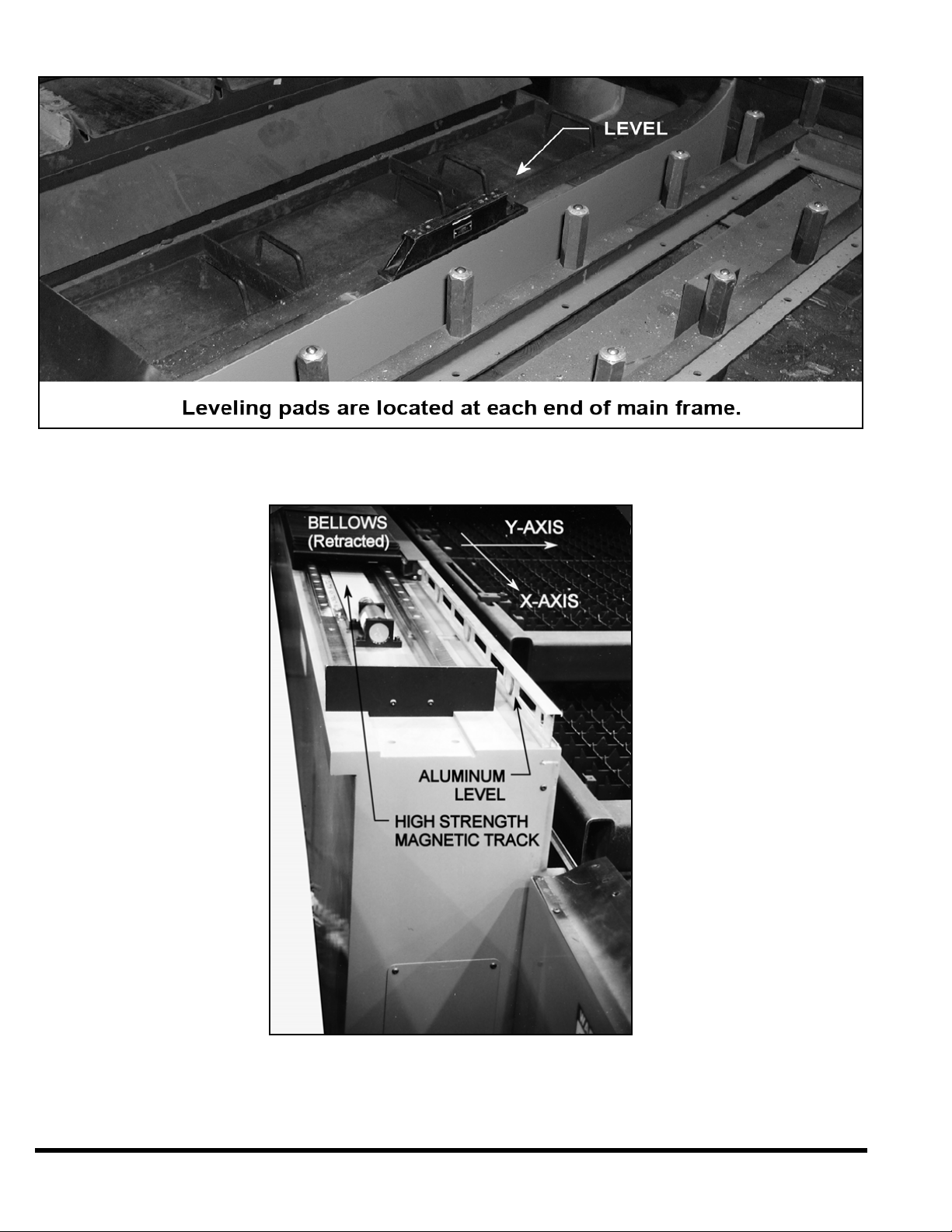
1. To check cross-leveling, place a precision level on machined pads on each end of the main frame. For
preliminary leveling, a level with .004 inch/ft. precision is sufcient (0.33 mm per meter). See Figures 2-3.
and 2-4. Lift machine with jackscrews and shim under mounting feet (shims are provided).
2. Longitudinal level is checked on the top of the X-axis guide way. Adjust as described above. See Figure 2-5.
Longitudinal leveling does not require a precision level.
A very powerful magnetic eld surrounds the
magnet track. Keep all metal (steel) tools away
from this track. Place a piece of wood (2x4) over
the magnetic track to protect it and personnel.
2-4
EM-573 (N-04-18)
Figure 2-4 Cross Leveling (Preliminary)
Figure 2-5 Longitudinal Leveling
Other manuals for CL-900 Series
1
Table of contents
Other Cincinnati Measuring Instrument manuals


