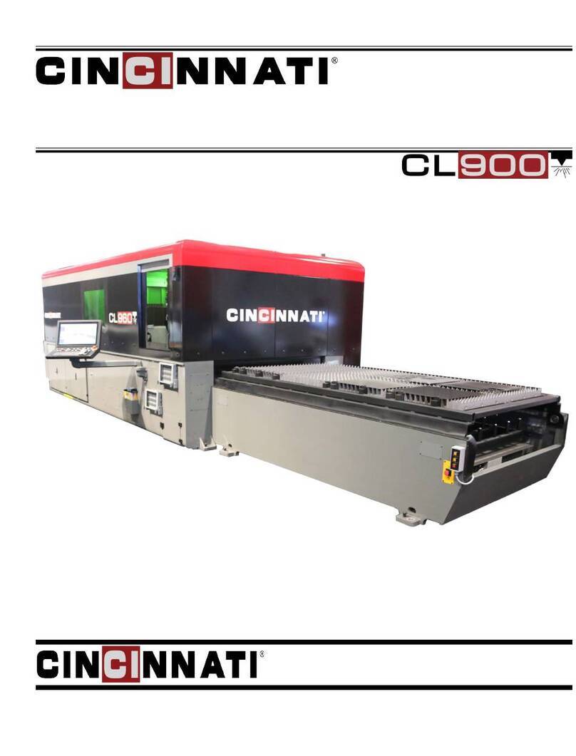
Cincinnati CL-900 Series User manual

OPERATION, SAFETY, AND MAINTENANCE MANUAL
CL-900 SERIES LASER SYSTEM
(IPG FIBER LASER RESONATORS - 5x10, 6x12, 8x20
FRAME)
CINCINNATI INCORPORATED
C I N C I N N A T I, OHIO 4 5 2 1 1
EM-552 (R-09-16) COPYRIGHT 2016
CINCINNATI INCORPORATED

1-1 EM-552 (R-09-16)
SECTION 1 IDENTIFICATION
CINCINNATI CL-900 SERIES LASER SYSTEM - FIBER LASER
1. ENCLOSURE
2. OPERATOR DOOR
3. LASER STATUS INDICATOR LIGHT
4. MATERIAL SUPPORTS
5. MATERIAL CLAMPS
6. LOWER PALLET
7. E-STOP BUTTON
8. BALL TRANSFER REMOTE (OPT)
9. LOAD FRAME
10. PALLET DOOR
11. REMOTE STATION
12. SCRAP BIN ACCESS DOOR
13. OPERATOR CONTROL STATION
14. MAIN FRAME
15. CONTROL ENCLOSURE
16. POWER ENCLOSURE
Figure 1-1 Front View

1-2
EM-552 (R-09-16)
7
8
6
5
1
2
4
3
1. CHILLER
2. CHILLER MAIN DISCONNECT
3. GAS AND COOLANT CONNECTIONS
4. TRANSFORMER
5. MAIN DISCONNECT
6. MAIN BREAKER INTERLOCK BYPASS KEY
7. POWER ENCLOSURE
8. CONTROL ENCLOSURE
Figure 1-2 Rear View

1-3 EM-552 (R-09-16)
2
3
4
5
6
1
1. I/O ENCLOSURE
2. DRIVE ENCLOSURE
3. ENCLOSURE
4. LASER STATUS INDICATOR LIGHTS
5. FIBER LASER E-STOP
6. FIBER LASER MAIN DISCONNECT
Figure 1-3 Rear View

1-4
EM-552 (R-09-16)
1 7
2
5
4
6
3
1. X-2 AXIS WAY COVER
2. ASSIST GAS PROPORTIONAL VALVES
3. Y-AXIS CABLE CARRIER
4. LEFT GANTRY ENCLOSURE
5. Z-AXIS FIBER CABLE CARRIER
6. RIGHT GANTRY ENCLOSURE
7. SCRAP TRAYS AND SCRAP TRAY CAPS
Figure 1-4 Rear View of the Gantry

1-5 EM-552 (R-09-16)
8
5
6
7
4
2
1
3
1. ASSIST GAS HOSE
2. Z-AXIS MOTOR
3. AUTO FOCUS HEAD DOOR
4. 10 INCH LENS DRAWER (EMPTY MANIFOLD SEAL)
5. 7.5 INCH LENS DRAWER (EMPTY MANIFOLD SEAL)
6. 5 INCH LENS DRAWER (INSTALLED)
7. LOWER TIP ASSEMBLY
8. Z-AXIS CABLE CARRIER
Figure 1-5 Y-Plate and Auto Focus Head Assembly

1-6
EM-552 (R-09-16)
3
2
1
5
4
6
1. PALLET DOOR REGULATOR
2. SUPPLY MANIFOLD
3. AIR SUPPLY MANIFOLD
4. N2REGULATOR FOR OPERATION STATION
5. RETURN MANIFOLD
6. ASSIST GAS FILTERS
Figure 1-6 Pneumatic Enclosure
ASSIST GAS
FILTER
Figure 1-7 Y-Plate Assembly Rear View

2-1 EM-552 (R-09-16)
SECTION 2 INSTALLATION
IMPORTANT: Before proceeding, contact CINCINNATI
Laser Service for pre-installation instructions.
LIFTING AND MOVING
Machine weights are provided in Section 4 -
SPECIFICATIONS.
The main frame is lifted using four standard lifting
clevises attached to four lifting links (C.I. Part # 920584)
with spacers (C.I. Part # 921838). The four lifting links
(supplied by CINCINNATI) are attached to the inside of
the main frame with 1”-8 UNC SHCS bolts. See Figure
2-1.
When lifting with chains, cables, or straps, use the maximum
length possible to reduce the side loading generated at the
lift points. Use spreader bars or intermediate lifting beam
if ceiling height will not allow a high pick.
Before lifting the main frame, be sure that lifting
links (C.I. # 920584) and spacers (C.I. # 921838)
are installed. Do not use eyebolts or other devices
not designed for excessive side loads. Using
improper lifting devices could result in serious
injury or death to bystanders and/or cause
extensive damage to the main frame and ber
laser.
IMPORTANT: Extreme care must be taken not to subject
the machine to shock loads. The machine must be
lifted and set down gently.
The load frame can be lifted using straps with S-hooks at
each of the four outer corners. The S-hooks are hooked in
the access holes located at the bottom of the load frame.
Adequate padding must be used at all points to protect the
machine’s nish. The straps can be gathered and lifted with
a hook attachment. See Figure 2-2.
Figure 2-1 Lifting Main Frame
Figure 2-2 Lifting Load Frame

2-2
EM-552 (R-09-16)
FOUNDATION
A Foundation Plan drawing is provided shortly after the
machine is ordered. This drawing provides the user with
detailed information required to locate the equipment and
the eight machine anchors. The customer should prepare
the eight anchor locations prior to arrival of the equipment.
The eight pads must be pre-leveled to lie in the same plane
within .50 inches (12.7 mm), and the anchor holes should
be drilled as specied on the Foundation Plan drawing.
CINCINNATI INCORPORATED provides anchors, studs,
nuts, and shims for nal leveling.
If the machine is to be installed near shock inducing
equipment such as punch presses, turret punches, etc.,
contact CINCINNATI INCORPORATED.
INSTALLATION OF MACHINE
After setting the machine on the anchor studs, place
washers and nuts on studs, but do not tighten. Installation
consists of the following steps:
1. Remove lifting clevises and spacers.
2. Remove all steel banding and protective wrappings.
3. Install fume fan (optional) and fume duct connecting
to fume plenum with ange and fasteners provided.
Seal connection with a bead of RTV silicone. Make
the electrical connection to the fan drive motor with
wiring provided.
4. Connect the customer-furnished fume exhaust system
to the fume duct exit port.
5. Complete preliminary leveling procedure described
below.
6. CINCINNATI Service will install the operator control
station and complete nal electrical connections to the
control.
7. Install gas lines, wiring, and hoses as described in the
pre-installation manual.
CHILLER
The water chiller is a free-standing unit requiring only oor
support. Cooling lines are connected to the main frame and
laser at the gas and coolant location mounted to the rear
of the machine. Hoses are furnished to connect the chiller
when located as shown on the Foundation Plan. Consult
CINCINNATI INCORPORATED if an alternative chiller
location is required. See Section 4 - SPECIFICATIONS
for chiller uid specications.
LEVELING
Main frame leveling adjustments are made using
jackscrews provided at the mounting pads. Figure 2-3
shows the mounting pads. The machine foot mounting
pads are located on the outside surface of the main frame
in the four corners.
Figure 2-3 Main Frame Leveling Adjustments

2-3 EM-552 (R-09-16)
Slotted shims are inserted between the machine foot and
steel spacer block as shown on the Foundation Plan drawing.
After shims are inserted, jackscrews are to be backed off
or removed. The procedure for leveling is described in the
next sections.
PRELIMINARY LEVELING
1. To check cross-leveling, place a precision level on
machined pads on each end of the main frame. For
preliminary leveling, a level with .004 inch/ft. precision
is sufcient (0.33 mm per meter). See Figures 2-3 and
2-4. Lift machine with jackscrews and shim under
mounting feet (shims are provided).
2. Longitudinal level is checked on the top of the X-axis
guide way. Adjust as described above. (See Figure
2-5.) Longitudinal leveling does not require a precision
level.
A very powerful magnetic eld surrounds the
magnet track. Keep all metal (steel) tools away
from this track. Place a piece of wood (2x4) over
the magnetic track to protect it and personnel.
FINAL LEVELING
Final leveling should be done with a CINCINNATI
INCORPORATED Service Representative present.
The purpose of nal leveling is to ensure that the gantry
does not rotate about the X-axis as the gantry moves from
end-to-end. Excessive rotation will cause laser beam
misalignment during operation.
1. Use a 15 inch (380 mm) precision spirit level with a
sensitivity of .0005 inch/ft. (0.04 mm per meter).
2. Place the level on the top of the gantry and position the
gantry at X = zero. See Figure 2-6. The gantry may be
moved by manually pushing it when drives are off, or
by using JOG mode when drives are on.
3. The top of the gantry is not machined. Therefore, it
will be necessary to shim one or both ends of the level
to establish a reference reading and make the level
sit solidly in place. Paper shims can be used for this
purpose.
4. Observe the position of the bubble while moving the
gantry from X = zero to X = Maximum travel. The
maximum acceptable deviation is one division of the
level (.0005 inch per ft. or 0.04 mm per meter) as the
Figure 2-4 Cross Leveling (Preliminary)

2-4
EM-552 (R-09-16)
Figure 2-5 Longitudinal Leveling
Y-AXIS
PLACE SHIMS
UNDER END
OF LEVEL TO
ESTABLISH
REFERENCE
READING
OR PRESS
LEVEL INTO
PLUMBERS
PUTTY TO
SECURE AND
HOLD LEVEL
IN POSITION.
.0005”/Ft
PRECISION LEVEL
Figure 2-6 Final Leveling with Precision Level

4-1 EM-552 (R-09-16)
SECTION 4 SPECIFICATIONS
SPECIFICATIONS
LASER RATED
POWER
TYPICAL
RANGE
YLS-2000 2000 W 200-2000 W
YLS-4000 4000 W 400-4000 W
WAVELENGTH: 1.07 micron
MODE: CW, QCW
LASER: Class IV
MAXIMUM WORKPIECE:
MODEL
WORKPIECE
DIMENSIONS
EVENLY
DISTRIBUTED
LOAD
X Y CAPACITY *
5 X 10 120 in.
(3048 mm)
60 in.
(1524 mm)
2292 lb.
(1134 kg)
6 X 12 157.5 in.
(4000 mm)
78.75 in.
(2000 mm)
3948 lb.
(1588 kg)
8 X 20 240 in.
(6096 mm)
98.5 in.
(2500 mm)
6690 lb.
(3035 kg)
* ACTUAL PROCESSING CAPACITY DEPENDS ON MATERIAL TYPE
MAXIMUM MATERIAL THICKNESS FOR
CLAMPING: .63 inch (16 mm)
Note: The nozzle must be at least 0.80 inches (20 mm)
above the material to avoid interference with the
clamps. If the nozzle is closer to the material (for
example, after cutting), then the program must
raise the Z-axis before moving the cutting head
near the material clamps.
CUTTING RANGE: The cutting head can move through
the range of X and Y-axis machine coordinates shown
in the table. A restricted area can be enabled around
each material clamp, preventing the cutting head from
moving through these areas. Alternately, the material
clamps can be repositioned or removed entirely. The
minimum distance between the Autofocus head and
a clamp is one inch (25.4 mm). See Figure 1-1 for
material clamp locations.
Except in the restricted areas, if enabled, the cutting
head can move approximately 0.5 inches (12 mm)
beyond the specied cutting range. The program can
use this extra movement for workpiece edge detection
(optional) or to cut off an oversized workpiece.
DIMENSIONS
COMPONENT MODEL
WIDTH LENGTH HEIGHT WEIGHT
Shipped Installed
In.
(mm)
In.
(mm)
In.
(mm)
In.
(mm)
Lbs.
(kg)
MAIN FRAME
5 X 10 125 183 268 97 23,200
(1.5 X 3.0 m) (3175) (4648) (6808) (2464) (10524)
6 X 12 144 202 268 97 27,200
(2.0 X 4.0 m) (3658) (4648) (6807) (2464) (12338)
8 X 20 160.5 274 414.2 99.1
(2.5 X 6.1 m) (4077) (6960) (10521) (2517) (11135)
LOAD FRAME
5 X 10 84.25 134 40 8,750
(1.5 X 3.0 m) (2140) (3404) (991) (3969)
6 X 12 103 161 40 10,200
(2.0 X 4.0 m) (2616) (4090) (991) (4631)
8 X 20 122.25 270 41 22,900
(2.5 X 6.1 m) (3105) (6858) 41 22,900
CHILLER
CL-920 (60 Hz) 33 52 66 900
(839) (1321) (1677) (409)
CL-940 (60 Hz) 42 52 64 1200
(1067) (1321) (1626) (544)

4-2
EM-552 (R-09-16)
CUTTING RANGE
MODEL X-AXIS Y-AXIS Z-AXIS
5 X 10 0 TO 120 in
(0 TO 3048 mm
0 to 60 in
(0 to 1524 mm) 0 to 1.5
in. (0 to
38 mm)
above
each
pallet
6 X 12 0 to 157.5 in.
(0 to 4000 mm)
0 to 78.75 in
(0 to 2000 mm)
8 X 20 0 to 240 in.
(0 to 6096 mm)
0 to 98.5 in.
(0 to 2500 mm)
ACCURACIES:
♦ Absolute Positioning (X and Y-axis): ±0.001 inch
(0.025 mm)
♦ Repeatability (X and Y-axis): .001 inch (0.025 mm)
MACHINE SPEEDS (Programmed moves):
♦ Cutting feed rate is programmable up to the Rapid
Traverse Speed. Maximum feed rate depends on
material type and thickness.
♦ Rapid Traverse Speeds
X and Y-axis: 8500 IPM (3.6 m/sec.)
X and Y-axis Simultaneous: 12020 IPM (5.1 m/min.)
Z-axis: 1700 IPM (0.7 m/sec.)
♦ Accelerations
X and Y-axis: 5 X 10: 1.65 G (16.2 m/sec2)
X and Y-axis: 6 X 12: 1.50 G (14.7 m/sec2)
Z-axis: 2.00 G (19.6 m/sec2)
MACHINE SPEEDS (In JOG Mode):
♦ Normal jog (X and Y-axes): 300 IPM (0.1 m/sec.)
♦ Rapid traverse jog (X and Y-axes): 1200 IPM
(0.5 m/sec.)
♦ Z-axis Speed: 250 IPM (0.1 m/sec.)
PROGRAMMABLE ASSIST GASES: Three
PROGRAMMABLE ASSIST GAS PRESSURE:
5-200 PSIG (34 to 1379 kPa) for Oxygen and 5-500
PSIG (34 to 3447 kPa) for Nitrogen and Air.
CHILLER FLUID:
♦ Circuit #1: This circuit services the laser source, and
should be supplied with distilled water only.
♦ Circuit #2: This circuit services the rest of the machine
(linear motors, cutting head, control enclosure, etc.),
and should be supplied with a solution of distilled
water and 30% to 35% Dowtherm SR-1 or 35% to
40% Dowfrost HD by volume.
The minimum specication for heat transfer uid
(30% Dowtherm SR1 or 35% Dowfrost HD) is
required to provide corrosion protection. Maintain
the minimum concentration according to the
Preventative Maintenance instructions in Section
9. If these additives are not available, consult
CINCINNATI INCORPORATED for approval of a
comparable product from another supplier.
Tap water must meet the following quality requirements
to be used in place of distilled water in circuit #2:
Maximum Hardness: 200 mg CaCO3/liter
Maximum Cl Concentration: 50 mg/liter
pH Range with additive: 6.5 to 8.0
Maximum Conductivity: 1000 µ S /cm
CHILLER TEMPERATURE SET POINT:
♦ Circuit #1: 71.6°F (22°C)
♦ Circuit #2: 80°F (26.6°C)
FUME EXHAUST RATING:
MODEL EXHAUST
FLOW
WATER STATIC
PRESSURE
5 X 10
6 X 12
4500 SFCM
(127 m³/min.)
0.75 in.
(19 mm)
8 X 20 6500 SFCM
(184 m³/min.)
4.0 in.
(102 mm)
Notes: Fume exhaust ratings are nominal recommended
rates that will provide adequate fume removal
when cutting mild steel or stainless. The optional
fume blower (see Section 8 - OPTIONS) can
achieve an exhaust rate of up to 6500 SCFM (184
m3/min).
Fume exhaust ow rate depends on customer-
installed exhaust ducts. Longer or smaller diameter
duct runs may reduce ow to an unacceptable
level. The diameter of the duct should match
the diameter of the fume fan connection ange.
Consult with a professional HVAC engineer for
recommendations.
Always review Material Safety Data Sheet for the
material being processed to aid in determining the
nature and composition of fumes being released.
See Section 3 - SAFETY of this manual for more
information.

4-3 EM-552 (R-09-16)
PIPING CONNECTIONS
ASSIST GASES: Three male 9/16 inch-18 straight thread,
37° JIC ttings are supplied for assist gas connections.
These ttings are threaded into 1/4 inch NPT ports on
the gas inlet lters manifold and may be removed if a
different type of connection is required.
FUME EXHAUST: The exhaust connection is a ange
for 20.38-inch (508 mm) diameter duct. The ange has
holes for eight bolts .312-inch (8 mm) diameter equally
spaced on a 23.25-inch (552.5 mm) diameter bolt circle.
The customer must provide connecting exhaust duct
with minimum 20-inch (508 mm) diameter.
The optional fume blower for the 8x20 model is a
rectangular port. The dimensions and bolt pattern are
shown on the foundation plan drawing.
EXTERNAL OPTICAL ELEMENTS
FIBER COUPLING: The ber optic cable terminates at
a quartz block. This quartz block is then mounted in
the collimator by a special coupling called the QBH
ber coupling. This coupling has an interlock that only
allows the laser beam to be delivered if it is connected
to the collimator.
FOCUS LENS: The standard cutting head uses a focus
lens with a 10.0, 7.5, or 5.0 inch working distance. The
cutting head has three lens locations. Install the required
focus lens in one location and an “empty manifold seal”
(EMS) in the other two locations.
LENS
LOCATION
WORKING
(MOUNTING)
DISTANCE
EFFECTIVE FOCAL
LENGTH (EFL)
5 inch
(Lower)
5 inch
(127 mm)
(4.85 inch
(123.4 mm)
7.5 inch
(Middle)
7.5 inch
(191 mm)
7.63 inch
(194 mm)
7.87 inch
(200 mm)
4,000 W only
10 inch
(Upper
10.0 inch
(254 mm)
10.12 inch
(257 mm)
GAS REQUIREMENTS
The Laser System uses different independently regulated
gas supplies to assist the cutting process, and to protect the
beam delivery optics. Gas requirements are listed in Table
4-1.
1. Programmable Assist Gas: Two programmable
valves control the assist gas pressure commanded by
the program for piercing and cutting. One valve is for
oxygen and the other is for nitrogen or air. The oxygen
has a pressure range from ve to 200 PSI (34 to 1379
kPa) and the nitrogen and air has a pressure range from
ve to 500 PSI (34 to 3447 kPa).
For accurate pressure control, the supply pressure
maintained at the machine inlet port must be higher
than the desired nozzle pressure in a dynamic ow
condition. The additional pressure required at the inlet
GAS
USE
GAS
TYPE
MANIFOLD
LABEL
GAS
PURITY
TYPICAL
PRESSURE
REGULATOR
SPECIFICATION
APPROXIMATE GAS
USAGE
ASSIST
GAS #1
Oxygen
(O2)
Assist
Gas #1 99.80 % See
TABLE 4-2
10 to 650 PSI
O2Compatible
CGA 540
See TABLE 4-2
ASSIST
GAS #2
Nitrogen
(N2)
Assist
Gas #2 99.80 % See
TABLE 4-3
10 to 650 PSI
CGA 580 See TABLE 4-3
ASSIST
GAS #3 Air Assist
Gas #3
See
TABLE 4-5
See
TABLE 4-4 0.50 in. NPT See TABLE 4-3
NOZZLE
COOLING
Dry
Compressed Air
or N2
Air Blast
No oil
or water
droplets
Variable
60 to 90 PSI
10 to 300 PSI
0.25 in. NPT Variable
NOZZLE
COOLING
Dry Air from
Air Dryer N / A
No oil
or water
droplets
N / A N / A 125 SCFH *
* This table species purge and nozzle cooling gas requirements for the laser system. The air dryer also requires 350 SCFH of “self purge” air. See
the foundation print for total air ow requirements at machine inlet.
TABLE 4-1 Gas Requirements

4-4
EM-552 (R-09-16)
port increases with the gas ow rate. At maximum ow,
the inlet pressure must be 100 PSI (690 kPa) above the
nozzle pressure. The maximum static system pressure
must not exceed 550 PSI (3792 kPa).
The gas supply system must be capable of delivering
assist gas at the required ow determined by the nozzle
pressure and orice size (see Tables 4-2 and 4-3).
Nozzle
Pressure
(PSI)
Approximate Flow (SCFH)
Required for Nozzle Orice
.060 in. .080 in. .060 in.
Double
15 82 157 82
25 111 209 111
50 181 333 181
75 252 471 252
100 322 610 322
TABLE 4-2 Oxygen Gas Flow
Tables 4-2 and 4-3 apply to single orice nozzles. To
estimate assist gas ow for nozzles with more than
one orice, contact CINCINNATI INCORPORATED
Laser Applications.
Nozzle
Pressure
(PSI)
Approximate Flow (SCFH)
Required for Nozzle Orice
.060 in. .080 in. .100 in. .125 in.
15 87 164 230 398
25 118 216 320 532
50 192 345 530 867
75 268 485 732 1324
100 342 624 939 1649
150 492 896 1347 2320
200 641 1168 1758 2878
250 790 1440 2166 3548
300 940 1712 2576 4219
TABLE 4-3 Nitrogen or Air Assist Gas Flow
When using air for assist gas, the ow and pressure
capacity of the air supply system (compressor and piping)
determines the maximum pressure available to the cutting
head. To nd the required air ow, see Table 4-3. To
nd the required air supply pressure for typical nozzle
pressures, see Table 4-4. Do not exceed the 250 PSI (1724
kPa) maximum inlet pressure of the refrigerated air dryer.
Nozzle
Pressure
(PSI)
Air Supply Pressure (PSI)
Required for Nozzle Orice
.060 in. .080 in. .100 in. .125 in.
100 125 145 176 196
105 131 156 183 202
110 136 157 189 209
115 142 163 196 216
120 148 170 202 223
125 153 176 208 230
130 156 182 216 236
135 164 188 221 244
140 176 196 228 251
145 179 201 236 256
150 181 207 241 264
155 187 213 247 276
160 192 216 256 278
165 196 226 260 285
170 203 232 266 292
175 209 238 273 296
180 216 244 276 306
185 220 250 286 316
190 226 256 292 320
195 231 263 296 327
200 236 276 305 334
205 242 279 316 341
210 248 282 318 348
215 256 288 324 355
220 259 294 331 362
225 264 296 337 359
230 270 306 344 376
235 276 316 350 383
240 281 319 357 390
245 287 325 363 397
250 292 336 370 404
255 296 338 376 411
260 303 344 382 418
265 309 350 389 425
270 316 356 395 432
275 320 362 402 439
TABLE 4-4 Nitrogen or Air Assist Gas Supply Pressure

4-5 EM-552 (R-09-16)
Compressed air used for assist gas must meet the following
purity specications at the cutting head:
Air Assist Gas Purity
Residual Oil
Carryover
< 0.003 PPM by weight,
including vapors
Particle
Carryover
< 0.01 micron,
99.999% DOP
(Dioctyl Phthalate) test
Pressure Dew
Point ≤+38 °F
TABLE 4-5 Air Assist Gas Purity Specications
IMPORTANT: Regulated assist gas supply pressure
must not exceed 550 PSI (3792 kPa).
Over-pressure will cause damage to
downstream components.
The very low temperature of cryogenic gas
supplies may cause hoses in the Laser System to
fail when high assist gas ow rates are used. An
external evaporator may reduce this effect. Refer
to the gas supplier for additional information.
For machines that have the Assist Gas Air Dryer Option, the
air supplied at the connection to the machine must meet the
purity class of ISO 8573-1:2010 [5:6:4]. See purity class
summary below. For complete purity class requirements,
see ISO 8573-1:2010.
○ Maximum number of particles per m3: ≤100,000
particles between the sizes of 1.0 µm and 5.0 µm.
No particles > 5.0 µm.
○ Pressure dew point: ≤ +10°C
○ Concentration of total oil: ≤ 5 mg/m3
2. Rapid Pierce: Compressed air is required for the air-
blast system used with rapid pierce. The air supplied at
the connection to the machine must meet the purity class
of ISO 8573-1:2010 [5:4:4]. See purity class summary
below. For complete purity class requirements, see
ISO 8573-1:2010.
○ Maximum number of particles per m3: ≤100,000
particles between the sizes of 1.0 µm and 5.0 µm.
No particles bigger than 5.0 µm.
○ Pressure dew point: ≤ +3°C
○ Concentration of total oil: ≤ 5 mg/m3
Figure 4-1 Schematic of compressed air supply system for purge requirements. “Basic” system components and
recommended pretreatment (*) components to comply with air dryer inlet specications.

4-6
EM-552 (R-09-16)
3. Purge Air Dryer Supply: The purge air dryer requires
up to 478 SCFH (14 cubic meter/ hour), 90 PSI
minimum (620 kPa). The air supplied to the machine
must be less than 100°F (38°C) and must meet the
purity class of ISO 8573-1:2010 [5:4:4]. Air outside of
this purity class could overwhelm and contaminate the
instrument grade air dryer, the laser system piping, and
the beam delivery optics. This damage is not covered
by warranty. If incoming air is hot, a refrigerant dryer
prior to the instrument grade dryer may be required.
4. Nitrogen for Beam Purge: The laser system can
use welding grade nitrogen regulated to 30 PSI (207
kPa) for beam purge. However, at 480 SCFH (13.6
standard m3/hr), the operating cost is usually higher
than ltered air.
5. Nozzle Cooling: The standoff accuracy of the
noncontact cutting head can change if the nozzle tip
assembly absorbs too much heat. This condition can
occur when using Rapid Pierce or when cutting material
with a highly reective surface. A noncontact cutting
head with Nozzle Cooling maintains standoff accuracy
by reducing the amount of absorbed heat. Compressed
air owing around the outer cone removes heat from
the nozzle tip assembly. The Laser System control
opens a solenoid valve to provide nozzle cooling
whenever the fume exhaust fan is running.
AMBIENT TEMPERATURE
105°F (40°C) maximum
50°F (10°C) minimum
Optional equipment modications are available to extend
the ambient temperature limits. Contact CINCINNATI
INCORPORATED Laser Technical Services for more
information.
CAPACITIES
Cutting feed rates are determined by material type,
thickness, surface condition, required part accuracy, laser
power, and proper machine setup.
PRINCIPLE OF OPERATION
The Fiber Laser System produces two-dimensional
contoured shapes from at material by moving a focused
laser beam along a programmed path. The beam from
a stationary ber laser is directed to a moving lens by
a ber optic cable routed through a moving gantry. The
workpiece remains stationary while a narrow strip of
material is removed along the path made by the lens.
Material is removed by vaporization and melting where
the lens concentrates laser power into a small spot on the
workpiece. Assist gas is also used to control the cutting
process.
The gantry moves the lens to produce the programmed
workpiece geometry. A motion controller commands servo
drives to control the gantry motion. The program provided
by the user includes commands to specify feed rate, laser
power, and assist gas.
The Laser System is equipped with an exhaust system,
which draws air down from the cutting area to assist in
the removal of process by-products. See Section 3 -
SAFETY.
CONTOURING ACCURACY
Contouring accuracy is a function of the feed rate and the
curvature of the path. The maximum feed rate at which
the Laser System can maintain a given hole roundness is a
function of the hole diameter.

6-1 EM-552 (R-09-16)
SECTION 6 MACHINE CONTROLS
OPERATOR CONTROL STATION
This section describes the individual controls located on
the Operator Control Station. Refer to Figures 6-1, 6-2,
and 6-3 for actual component locations.
Touchscreen: The touchscreen is a device for monitoring
various conditions of the Laser System and selecting
various control functions. The operator can access several
categories of information, such as: Programs, Material
Processing Parameter Libraries, Axes Positions, Offsets,
Program Modes, and Messages. Buttons displayed on the
screen can be selected with the trackball or by touching the
screen.
Front Panel Controls: Between the touchscreen and
keyboard is a panel with pushbutton/indicators to start and
stop the machine, reset the control, jog the X, Y, and Z
axes, and move the pallets. These controls are described in
detail in this section.
Keyboard: The keyboard is used to enter alphabetic,
numeric, and other characters into the control for program
and data entry. The keyboard can also be used to open and
close windows in the control application, and to select
menu items.
Trackball: The trackball assembly provides the functions
of a computer mouse without requiring as much space.
The operator can rotate the ball to move the cursor, and
then press the left or right button to select functions on the
screen. The trackball also has a dial to scroll up or down
when the selected window supports that function.
Side Panel Controls: On the side of the Operator
Control Station is a panel with three keyswitches and one
pushbutton/indicator. These controls are described in detail
in this section.
Figure 6-1 Operator Control Station

6-2
EM-552 (R-09-16)
USB Connector: On the side of the Operator Control
Station is a USB (Universal Serial Bus) connector. If a
network server is not available, operators can use the USB
port to load or backup programs and process library les.
USB ash drives can be purchased from most computer
stores.
MACHINE OPERATOR PANELS
The Operator Control Station has a front panel with several
pushbuttons and indicators, and a side panel with one
pushbutton/indicator and three keyswitches. (See Figure
6-1.)
FRONT PANEL CONTROLS
The front panel pushbutton/indicators can be categorized
in four groups: Program Controls, Axis Jog Controls, Pallet
Controls, and Emergency Stop. See Figure 6-2.
PROGRAM CONTROLS
Figure 6-3 Front Panel - Program Controls
CYCLE START pushbutton/indicator: This pushbutton
performs different functions depending on the control
mode. When the control is in AUTO mode, pushing this
button commands the laser system to begin executing
the loaded program. If an alarm condition changes the
control mode from “Executing” to CYCLE STOP, then
correcting the condition and pressing CYCLE START
resumes automatic operation. When the control is in
CYCLE STOP mode, the operator can also select the
TRACING function button and then press CYCLE
START to begin TRACING mode. When the control
is in AXES HOME mode, pressing CYCLE START
begins the automatic AXES HOME sequence.
The laser system illuminates the CYCLE START
indicator when executing the program or the AXES
HOME sequence.
CYCLE STOP pushbutton/indicator: When this button
is pushed during automatic operation, axis motion
decelerates to a stop, and all cutting functions such as
laser beam and assist gas are turned off. Cycle Stop
status is indicated by illumination of this indicator. The
indicator will be extinguished when the CYCLE START
button is pressed or the control is reset. Cycle Stop
status can also be achieved by pressing the FEEDHOLD
pushbutton located on the Remote Station.
RESET pushbutton: Press this button to reset the axes
drives (X, Y, and Z) or cancel an alarm message.
TRACE FORWARD pushbutton/indicator: This
pushbutton is only active when the control is in
TRACING mode. It is used to move the axes along
the programmed path in the FORWARD direction to
a position where cutting is to be resumed. If forward
motion is possible while in TRACING mode, this
pushbutton will be lit. (See Cutting Procedures / Error
Recovery in Section 7 - OPERATION, EM-551.)
TRACE REVERSE pushbutton/indicator: This
pushbutton is only active when the control is in
TRACING mode. It is used to move the axes along
the programmed path in the REVERSE direction
to a position where cutting is to be resumed. This
pushbutton will be lit if reverse motion is possible while
in TRACING mode. (See Section 7 - OPERATION,
EM-551, for more details.)
Figure 6-2 Front Panel Controls

6-3 EM-552 (R-09-16)
AXIS MOTION CONTROLS
Figure 6-4 Front Panel - Axis Motion Controls
X►pushbutton/indicator: Pressing this pushbutton will
jog the X-axis in the positive direction if the following
conditions exist:
○ Control is in JOG mode and the drives have been
enabled and homed.
○ Remote STATION ENABLE selector is not
activated.
Motion will stop when the pushbutton is released.
X◄pushbutton/indicator: Pressing this pushbutton will
jog the X-axis in the negative direction if the following
conditions exist:
○ Control is in JOG mode.
○ Remote STATION ENABLE selector is not
activated.
Motion will stop when the pushbutton is released.
Y►pushbutton/indicator: Same as X►pushbutton/
indicator except for Y-axis.
Y◄pushbutton/indicator: Same as X◄pushbutton/
indicator except for Y-axis.
RAPID TRAVERSE pushbutton/indicator: When the
RAPID TRAVERSE button is illuminated, and the X
or Y-axis is jogged from the Machine Operator Front
Panel, the jog speed is the value specied by the “X/Y
Rapid Jog Speed” parameter in the General page of the
Machine Conguration window. This function remains
active until canceled by pressing the illuminated
RAPID TRAVERSE pushbutton, or enabling the remote
station.
Note: To jog at the Rapid Traverse rate, the Z-axis must
be retracted.
Z UP pushbutton/indicator (+Z): Same as X►
pushbutton/indicator except for Z-axis.
Z DOWN pushbutton/indicator (-Z): Same as X◄
pushbutton except for Z-axis. The Z DOWN indicator
will illuminate whenever the Z-axis is moving down;
the Z DOWN indicator will also illuminate any time the
cutting head is actively tracking the material, using its
built-in capacitive sensor.
PALLET CONTROLS
Figure 6-5 Front Panel - Pallet Controls
UPPER PALLET IN, UPPER PALLET OUT,
LOWER PALLET IN, and LOWER PALLET
OUT pushbutton/indicators: Each pallet has two
pushbutton/indicators, to jog or indicate motion toward
the cutting position (IN) or toward the load position
(OUT). The indicators ash on and off whenever the
pallet is moving in the corresponding direction (in JOG
or AUTO mode). If the control is in JOG mode, the pallet
can be moved in the indicated direction by pressing the
corresponding button. Releasing the button will stop
motion. Each indicator will stop ashing and remain
on when a pallet has reached its end-of-travel position.
One “in” and one “out” indicator must be illuminated
for CNC program execution to be permitted.
PALLET NOT READY pushbutton/indicator: After
each program starts, the PALLET NOT READY
pushbutton/indicator is automatically illuminated. If the
program commands M50 (Pallet Exchange), the pallets
will not move while the PALLETS NOT READY
pushbutton/indicator is illuminated. When operators are
unloading or loading material on the pallet in the load
frame, this function helps protect them from unexpected
pallet motion.
Other manuals for CL-900 Series
1
Table of contents
Other Cincinnati Measuring Instrument manuals
