Cincinnati 1a lo User manual

seruice
mnnuRL
HOD
PARTS
LIST
CATALOG
.—--X
h,
•;-
£^^01
®
[CINCINNATI:
No.
1
Tooimaster
MILLING
MACHINE
Identification
No.
6J-DK
Publication
No.
M-2109
WHEN
ORDERING
REPAIR
PARTS
1.
Give
complete
Serial
Number
of
Machine.
2.
Give
Part
Number
and
Name.
3.
Give
Amount
Required.
UNLESS
THE
ABOVE
DATA
IS
INCLUDED
WE
CANNOT
FILL
YOU
R
ORDE
R
THE
CINCINNATI
MILLING
MACHINE
CO
CINCINNATI
9,
OHIO,
U.S
A.


SERVICE
MANUAL
AND
PARTS LIST
CATALOG
TABLE
OF
CONTENTS
This catalog to be used
only
for machines
whose
serial
number
begins
with
6J.
FUNCTIONAL
DIAGRAMS
DIMENSIONAL
DRAWING
CONVERSION CHART
(Inches
to
M/M)
LUBRICATION
DIAGRAM
AND
SPECIFICATIONS.
CMMCo.
RECOMMENDED
LUBRICANTS
......
INSTALLATION
INSTRUCTIONS
ADJUSTMENTS
To
Adjust
Gibs
Drive
Belts:
Styles
1-A,
1-B.
...
Drive
Belt:
Style
1-E
" "
Backlash
Eliminator
"
Quill
Powerfeed
Clutch:
Style
1-B
" "
Shaping
Attachment
Drive
Belt
...
" "
Shaping
Attachment
Gib
DISMANTLING
INSTRUCTIONS
To
Remove
V-Belt
Housing
Styles
1-A,
1-B
Style
1-D
Style
1-E
Splined
Spindle
Sleeve:
Styles
1-A,
1-B.
. . . . . , . .
Drive
Spindle
Assembly:
Style
1-A
:
Style
1-B
:
Styles
1-D,
1-E
Spindle
Housing
with
Spindle:
Styles
1-A,
1-B
....
" :
Styles
1-D,
1-E
...
.
Spiral
Gear
Shaft:
Style
1-B
Transmission
Shaft:
Style
1-B
Speed
Change
Assembly:
Style
1-D
and
Dismantle
Powerfeed
Housing:
Styles
1-D,
1-E.
Overarm
and
Turret:
Styles
1-A,
1-B,
1-D,
1-E
. .
Overarm
(Heavy
Duty):
Style
1-C.
and
Dismantle
Overarm
Gear
Housing:
Style
1-C
. .
Page
4,
5
6
7
8,
9
10
11
12
12
12
12
12
12
12
13
13
13
13
13
14
15
15
16
16
16
17
17
18
18
18

CINCINNATI
NO.
1
TOOLMASTER
MILLING
MACHINE
To
Remove
Single
Swivel
Housing
Spindle
and
Drive
—
Without
Hand
Feed:
Style
1-C
" "
Single
Swivel
Housing
Spindle
and
Drive
—
With
Hand
Feed:
Style
1-C
. .
" "
and
Dismantle
Double
Swivel
Housing:
Style
1-C
Table
" "
Table
Leadscrew
" "
Table
Powerfeed
Housing
To
Dismantle
Table
Powerfeed
Housing
To
Remove
Standard
Saddle
" "
Crossfeed
Screw
" "
and
Dismantle
Saddle
When
Table
Is
Equipped
With
Powerfeed
" " " "
Saddle
Powerfeed
Housing
Elevating
Crank
Shaft
" "
Elevating
Screw
and
Pedestal
Knee
To
Dismantle
Shaping
Attachment
To
Install
Table
or
Saddle
Powerfeed
Motor
KEY
NUMBER
INDEX
HOW
TO
ORDER
REPAIR
PARTS
HIGH
SPEED
HEAD AND
OVERARM
(Unit
6JJR)....
HEAVY
DUTY
HEAD AND
OVERARM
(Unit
6JJS)
...
VARI-SPEED
HEAD AND OVERARM (Unit 6JKV). . . .
SADDLE-TABLE
(Unit
6JH)
KNEE (Unit 6JK)
COLUMN
(Unit
6JC)
COOLANT
PUMP
AND
PIPING
(Unit
6JP)
PRECISION MEASURING
EQUIPMENT
(Unit
6JJL).
. .
SHAPING
ATTACHMENT
(Unit
6JHF)
PLAIN,
SWIVEL AND UNIVERSAL VISES (Unit 6JKA)
INDEX
HEAD
AND
TAILSTOCK
(Unit
6JKA)
MACHINE
INSTRUCTION
PLATES
The
design
and
specifications
of
these
machines
are
subject
to
change
without
notice.
Page
18
19
19
19
20
20
21
21
22
22
22
23
23
24
24
24
25-26
27
29-41
43-53
55-67
69-77
79-89
91
91
93-95
97-99
101
103
105
Publication
No.
M-2109

SERVICE
MANUAL
AND
PARTS
LIST
CATALOG
SPINDLE
DRIVE
MOTOR
TURRET
SWIVEL
LOCKING
NUTS
OVERARM
POSITIONING
PINION
SERIAL
NUMBER
PUSH
BUTTON
PANEL
TABLE
TRAVERSE
HANDWHEEL
KNEE
CLAMPS
SADDLE
CLAMP
FUNCTIONAL
DIAGRAM
SPINDLE
MOTOR
CONTROL
HEAVY
DUTY
OVERARM
(UNIT6JJS)
SPINDLE
SPEED
SHIFT
LEVERS
DOUBLE
SWIVEL
HOUSING
Figure
4A
Style
1C
Toolmaster
Milling
Machine
with
Heavy
Duty
Overarm
and
Double
Swivel
Housing
PINDLE
START-STOP
SWITCH
HIGH
SPEED
HEAD
AND
OVERARM
(UNIT6JJR)
QUILL
CLAMP
HEAD
ANGLE
ADJUSTMENT
COLUMN(UNIT6JC)
TABLE
(UNIT
6JH)
TABLE
CLAMP
CROSSFEED
KNEE(UNIT6JK)
ELEVATING
CRANK
Figure
4B
Style
IB
Toolmaster
Milling
Machine
with
Power
Feed
to
Quill,
Manual
Feed
to
Saddle
and
Table

CINCINNATI
NO.
1
TOOLMASTER
MILLING
MACHINE
FUNCTIONAL
DIAGRAM
Figure
5A
Style
IE
Toolmaster
Milling
Machine
with
Power
Feed
to
Quill
DRAW-IN
BOLT
LOCK
KNOB
SPINDLE
START-STOP
SWITCH
ID
HEAD
UNIT
6JKV
HI-LOW
SPEED
CHANGE
LEVER
POWER
FEED
ENGAGING
LEVER
QUILL
FEED
HANDWHEEL-
QUILL
CLAMP
POWER
FEED
TO
TABLE
UNIT
6JH
KNEE
UNIT
6
JK
DRAW-IN
BOLT
SPINDLE
START-STOP
SWITCH
SPINDLE
BRAKE
IE
HEAD-UNIT
6JKV
QUILL
FEED
HANDWHEEL
QUILL
CLAMP
Figure
5B
Style
ID
Toolmaster
Milling
Machine
with
Power
Feed
to
Quill,
Saddle
and
Table
Hi:
.\
SPEED
CHANGE
DIAL
SPEED
CHANGE
CRANK
SPINDLE
BRAKE
MICROMETER
QUILL
STOP
QUILL
HAND
FEED
LEVER
PRECISION
MEASURING
DEVICE
SADDLE-TABLE
UNIT
6JH
COLUMN
UNIT
6
JC
POWER
FEED
TO
SADDLE
UNIT
6JK
Publication
No.
M-2109
SERVICE
MANUAL
AND
PARTS
LIST
CATALOG
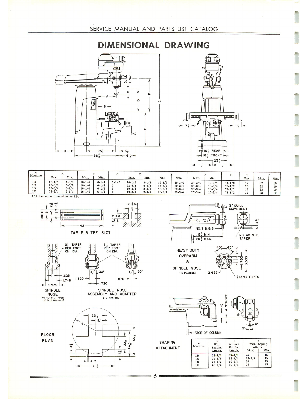
DIMENSIONAL
DRAWING
Machine
Max.
Min.
Max.
B
Min.
C
Max.
3
Min.
J
Max.
S
Min.
Max.
Min.
GH
Max.
Max.
I
Min.
-
IB
1C
ID
IE
22-1/4
25-3/8
23-3/4
23-3/4
4-3/4
5-3/8
6-1/4
6-1/4
16-1/4
16-1/4
16-1/4
16-1/4
6-1/4
6-1/4
6-1/4
6-1/4
3-
3
5
5
1/2
20-1/8
22-5/8
19-3/4
19-3/4
3-1/8
5-5/8
2-3/4
2-3/4
46-3/4
46-3/4
46-3/4
46-3/4
29-3/4
29-3/4
29-3/4
29-3/4
27-3/4
27-3/4
27-3/4
27-3/4
10-3/4
10-3/4
10-3/4
10-3/4
74-1/2
73-1/2
78-1/2
78-1/2
17
20
17
17
32
32
32
32
10
10
10
10
*
1A
has
same
dimen.
ions
as
IE
<•»
NO.
40
STD.
TAPER
(ID a IE
MACHINE)
FLOOR
PLAN
TABLE
a
TEE
SLOT
SPINDLE
NOSE
ASSEMBLY
AND
ADAPTER
( IB
MACHINE)
Ar
23^
-*-jll|
\
1N\
\i1vV 1
^/7
'i-
m
IO
ID
r
i_
^1 -
i— f i
r
^U-2
-*
78i
»~
1
Jx^J^i
^F^
NO.
7
b.
a
s.
<5jMIN-
J
25 1 MAX.
HEAVY
DUTY
OVERARM
a
SPINDLE
NOSE
1IC
MACHINE)
2.625
SHAPING
ATTACHMENT
J.-13NC
THRD'S.
FACE
OF
COLUMN
Machine
X
With
Shaping
Attach.
X
Without
Shaping
Attach.
With
S
Atta
Max.
Taping
ch.
Min.
IB
1C
ID
IE
33-1/2
37-1/8
33-1/2
33-1/2
37-1/8
38-1/4
39-3/4
39-3/4
24
28-1/2
24
24
15
15
15
15

o
b
o
on
45.
O
b
3
3
o
o
o
45.
4=>
to
4i.
H-*
4=>
to
J>
CO
I—"
CO
Co
i-*
to
Co
i—'
NT
NT
h~i
to
NT
t—•
NT
H-»
i—•
i-.
•—.
m
co
•OJ
00
(n
1—i
to
i—*
*-*
en
to to
-J
to
tn
-^t
CO
t—'
•—»
en
to
-OJ
•^J
OO
en
to
to
•-*
>—»
en
to
to
•^.l
i—'
cn
-J
OO
CO
M
en
to
H-»
-j
CO
cn
i—'
oo
1—1
I—i
\\
~v
\\ \ \\\ \ \ \ \
"V
-—
\\
•"—,
*\
S
•^
•\
^^
\,
\.
\.
\^
\
\,
\^\
\^
\,
\^
\,
*\
45.
Ol
to
fft
I—1
Ch
CO
(Ti
(TO
CT
co
Ol
H^
Ch
CO
Ch
NT
CT.
(o
Ch
1—i
CT,
CO
er
(XI
CT
CO
Ch
K-.
Ol
(o
o^
45. CT,
co
Ch
1—'
CT
Co
CT
00
CT
OO CT,
i—.
CT
OO
Ol
3
o
o-
<T>
-J
45.
to
45.
CT
4*
to
45.
45.
NT
4»
iDl
4i
NT
4^
4i
to
45.
CTi 45.
NT
45.
45.
to
45.
Ol
45.
NT
45. 45.
NT
45-
Ol
45.
to
45.
45.
NJ
45.
Ol
45.
NJ
45.
-0
~J
^1
Ch
Ch
or
Ch
Or
m
On
en
ejr
CJT
en
tn
cn
*.
45. 45.
45.
45.
45.
OO
Oo
CO
00
oo
CtJ
NT NT
NT
NT
NT
NT
NT
I—.
>-.
H-
h-'
1—'
H-'
o O o o O O
Cn
00
t—1 O
00
-J
on
45.
to
O
to
^j
CTl
4^
CO
i—*
O
00
(T,
en
CO
NT
O
to
-J
en
45.
NJ
I-*
to
(X) CTl
en
CO 1—* o(TO
-o
cn
-(5-
to
O
to
^J
CT
45.
OO I—*
0)
O45.
00
00
-J
i—i
Ol
O
en
to
CO
00
NT
<-^
i—•
en
e->
45-
on
CO
--.1
HI
CTi o
tn
tn
to
oo
NT
CT,
H-»
en
O
45.
OO
to
-o
>—'
CT
O
On
to
0O
oo
NJ
Ol
1—1
On
o5
oo
>—*
On
to
CO
Ch
O45.
oo
H-'
On
to
CO
Or
O45.
00
i—'
on
to
CO
Ch
O
-p.
00
i—.
C/l
to
Oo
CT
o45.
00
I-.
On
to
OO
Ol
O
45.
00
i—.
cn
to
co
Ol
lO
00
co
^J
^0
-0
Ch Ch
on on
On
45.
4^
CO CO CO
to to
h-'
I—.
h-*
o O
to to to
00
oo
-J
•<]
-0
CT
CT
On
On
cn
45. 45. CO
oo
CO
to
to
H-»
I—.
i-i
oo§
O
rr
NT
00
45.
o
Ch
to
OO
45.
e-r
CT,
NT
00
4*
O
-OJ
CO
to
en
h-*
-o
CO
to
CJl
i—,
•~J
CO
to
cn
H-1
^j
to
to
cn
I—.
^J
CO
to
On
t—1 •^T OO
to
cn
I—.
^T
Co
on
(/i
tn
en
cn
Ol
Ch
-J
•o.
-4
00
00
fX)
to to
to
OaoO
>-•
h-1
1-^
NT
to
ro
OO
0o
co
45.
45. 45.
en
On
cn cn
cn
CT
CT,
•^l
^t
•-J
00
oo
00
CO
to
to
~"\
O
CO
Ol
to
to
cn
00
i—•
en
0O
>—• 45.
•^J
e-r
to
Or
o
(o
CT.
to
NT
cn
CXI
1—.
C/l
oo
t-»
45.
^j
O
00
or
OOO CT,
liJ
to
cn
oo
i—'
on
00
)-.
45.
-^J
oOO
Ol
§
o
1-*
to
4>
On
Ch
^J
to
O
i—1
NT
4>
On
e^
•-]
to
o
h-*
to
45.
on
O-i
~J
to
o
H-*
NT
45.
cn
CT,
-J
to
o
H-*
NJ
45.
en
CT,
^j
to
O
t—'
NJ
-(5.
on
Ol
^J
to
<Tl
CO
CT,
k~»
en
ro
en
en
NJ
tn
i—i
cn
NJ
45.
CO
t—» I—1
en
to to
^-t
--J
cn
^)
CO
OO
h-.
On
to
oo
00
00
CO
to
to
KT
to
NT
to
NT
NT
NT
NT
\\
^^
\
—.
\^
-\
\
^s
*\
*-s^ ^
*\
~v.
*\
Co
to
)—I
O
to
Of)
-0
Ol
en
45.
CO
NT
H-1
o
to
OS
^J
Ch
en
4i
CO
to
1—.
o
to
to
~J
CT
On
4>
OO
NT
1-^
(T
CO
Ch
K-1
CT
CO CT,
oo
CT
OJ
OT
1—1
CT
OO
Ol
3
o
n
45.
NT
45.
o^
45.
to
45- 45.
NJ
45.
CT
45.
NJ
45.
to to
to
tn
to
to
00
00
oo
00
00
00
•~o
^J
•~o
on
CTl
en
(O
NJ
a
to
^4
en
45.
NJ
1—1
tiJ
00
Ol
45.
00
to
•~o M
Ch
O
cn
to
0J
(X)
NJ
OT
H-1
On
45.
00
h-»
cn
to
Oo
Ch
O45- CO 1—»
cn
to
OO
Ol
00
oo
-OJ
-o
o*0J
Ch
Ch
Ch
CT
en
en
en
en
4i
•£>
4i
45.
to
CO CO
(O
NT
ro
NT
NT
1—' i—•
h-'
^—'
CO
00
or
CO
>—•
00
Ch
to
©
oo
en
CO
e-T
r»
en
00
O
00
en
(O
o
^J
cn
to
o•^1
en
NJ
O
^J
en
NT NT
NJ
NT
ro
NJ
ro
NJ
NJ
ro
NJ
NJ
NJ
NJ
1—1
h-i
00
to
*o.
to
Ch
M
On
CD
on
to
4*
OO
CO CO
to
~J
\—>
em
I—.
<-n
o
45.
to
45.
cx>
CO
•~J
to
-~J
h-i
or
o
e-n
cn
45.
45.
oo
CO
OO
ro
NT
i—*
M•—' O
CJ
to
to
§
to
00
45.
r->
Ch
to
OO
4*
o
or
to
oo
4^
e-T
CTl
NT
t>0
45.
oCT,
to
oo
45.
O
CT
NT
00
45.
O
Ch
NT
00
45. O
(T,
NT
on
45.
©
CT
n;
oo
45.
o
CT
NJ
00
45.
oo o O © Oooo
<o <o
o O O O OoooO
e-T
oO O oo o oo o ooOoOo>—•
1—'
H-
NJ NJ NJ
OO
oo
CO
45.
45.
45.
^\.
o©oooooooO O ooooo o OoOa o aOooOOoOooo
CO
Ch
tn
NJ
On
OO
1—»
cn
00
I—.
45.
^1
e_> OO
Ol
g
o
1—.
NJ
45.
en
O-i
^J
to
oI—1
NJ
45.
cn
Ol
to
00
00
•-0)
-o;
-J
-0.
-0
-o
~0
-OJ
~J
-o
o>
Ch Ch
Ch
rr,
Ch
CT,
Ch
Ch
CT
cn cn
cn cn
en
en
en
en
tn
en
45.
45.
45>
45.
4^
45.
45.
45.
45. 45- CO
OO
CO
oo
OO
00
>—i
3
n
t—* o
to
00
•"J
Ol
On
4»
00
to
*-*
o
to
oo
-J
Ch
On
45- OO
NT
I—.
O
to
oo
•^J
Ch
cn
45. CO
NT
>—• o
to
00
-J
CT
cn
45.
OO
NJ
OJ
to
oo
Ol
cn
45.
3-
n
to
o
to
o
to
O
to
to
tn
to
oo
00 00
GO
•~J
-Oj
•OJ
-o
ch
(T.
CT, CT,
en en
on
45.
45. 45.
45.
CO
to
co
to
NT NT NT NT
h->
h-.
(—*
)-*
oo o O
to to
to
to
co
00
On
00
<->
00
en
CO
o
-oj
en
to
O
^1
en
to
O
~~4
en
NT
o
^l
45.
NT
to
^o
45.
NT
to
^J
45.
NT
to
-0
45.
l—i
to
fT
45.
h-»
to
CT,
4f
i—1
to
Ul
oo
^
00
Ol
%
-0
to
Ch
1—*
On
o
on
to
4»>
00
OO
oo
to
-Ol
t-*
Ch
H-»
ejr
o
45.
to
45.
OO OO
~J
NT
-0
I—1 CT, O
cn
O45-
CO
CO
00
OO
-^1
NJ
Ol
}—•
0)1
c_>
on
to
45.
to
CO
45.
O
Ch
ro
00
4=» O
Ol
to
oo
45.
oCTl
NT
oo
4±
o
Ch
NT
00
45. O
or
NT
00
ao
Ch
NT
00
45.
<n
CT
NT
OO
45.
O
CT
NT
00
45. o
er
ro
00
45.
o
Oi
%
oooo o o ooo o O o O O o OooooOoo o oo o O
CT
oOoO o oOoOO
e_)
e_)
e_J
e_)
o
e_)
O o
OJ
O o o
o
to
to
to
to
to
NT
to
to
to
NT
O
e-T
ooOooO
rr
o
to
to
to
to
tn
to
tn
tn
to
to
oa
OO
oo
OO
CO
00
oo
oo
•—i
3
n
to
co
-J
cr
On
4*
oo
to
Mo
to
00
^J
e^
CJl
42.
CO
to
,—'
o
to
00
^1
er
eji
45.
Oo
NT
h-«
o
to
CO
-J
CT,
On
45.
00
NT
O
to
oo
^j
Ul
Ul
45.
CO
to
3"
n>
CO
oo
00 00
CO
CO
00
CO
CO
to
CO
to
to
NT
NT
NT
NT
NT
ro
NT
NT NT NT
IO
NT
NT
NT
NT
NT
NT
NT
NT
NT
NT
N.
NT
NJ
NT
NT
NT
ro
NJ
to
NT
NT
NT
NT
to
ro
to
to
to
NT
M1—i
1—'
OOno
tn tn tn
tn
(XT (X)
(X)
00
•^J
^-1
-0
~J
Ch
CT
er
Ch
en
en
en en
45.
45.
45.
45.
(O
Oo
OO
OO
NJ NJ
NJ
1-^
h-•
i—i
o§
-o.
Cn
to
o
•OJ
45.
to
to
-oj
45.
NT
tn
•»)
4^
NT
to
•-4 4=>
>—'
to
IT,
45* 1—>
tn
en
45.
•-»
ten
CT
-P.
M
oo
Ch
CO 1—»
00
Ch
CO K
on
Ol
OJ
O
00
on
OJ
e_J
00
Ol
\-*
On
o
On
to
45.
00
CO
oo
NT
•~j
i—»
Ch
H-*
on
O
J>
to
45. (50
CO
-o
to
^j
H-»
eTi o
cn
O
4>
to
CO
00
CO
•^1
NT
or
H^
or
c_J
to
45.
tu
Oo
OO
"^
Ol
to
00
45.
O
Ol
ro
00
45.
o
Ch
ro
oo
4*
o
Ch
NT
00
45.
O
Ch
NT
ca
-P^
c
en
NT
oo
45.
e-T
CT
NT
00
45.
e-r
CT
NT
00
45.
o
er
NT
00
45.
o
CT
NT
00
§
oo O OooooOooooooOOoOOoOo o oooo O O O o oOOOOooo
OJ OJ
t_l
t_l
e-J
o
-J
-OJ
-J
-J
-J
»a
rn
Ch
Ch
Ch
(T.
Ch
Ch Ch
Ch
CT.
cn
en
en
en en
cn
Ol
en
en
en
45.
45.
.J>
45.
45. 45. 45. 45.
45.
45.
CO CO
CO
to
CjJ
OJ
OO
CjJ
OO CO 3
Cn
45.
Oo
to
H^
o
to
oo
^j
Ch
On
-f^
OO
to
1—' oCO
00
-J
CTi
cn
45.
00
to
H-.
o
to
OO
-o
Ol
on
45.
U)
NT
!—•
c_>
to
oo
u,
45.
OJ
i—i
©
3"
CA
..!>
*>
J>
45. 45.
4*
45. 45. 45.
4*
4^
4^
4^
4i.
4i
45.
45. 45.
co
CO
(.jj
CO
oo
CO
CO
co
to
CO
co
OO
00
OO
CO
OO
OO
CO
OJ
CO
co
CO
CO
CO
00
CjJ
0O
oo
4>
45.
to
(O
00
CO
to
ro
NT
NT
t—'
i—1
t-*
t—'
OOOO
to
tn to
to
00
(XI
oo
<X1
-.1
^l
•^i
^)
er
Ch Ch
CT
en
cn
cn
cn
45.
4^
45.
-15.
oo
0o
g
45.
to
Ol
45. I—1
to
oi
45.
1—«
to
CTl
J>
H-
(»
Ol
00
(-.
(TO
Ch
CO
•-'
00
en
CO
i—•
oo
en
CO
o
oo
en
CO
O
(XI
cn
OJ
o
NJ
o
CJl
NJ
o
On
to
45.
00 00
oo
to
~o
t—•
Ch
M
eji
o
4^
to
4*
00
OO
-J
NT
^J
V-«
CT, o
On
o
45.
to
CO
oo
OO
~J
NT
CT
1—*
O-i
o
cn
to
4^
to
CjJ
oo
£
Om
NT
00
45.
e->
Ch
NT
no
4±
O
ai
NT
00
4^.
O CT,
NT
00
45.
O
n\
NT
00
45. o
CT
NT
on
455.
(->
Ol
ro
00
45-
o
CT
to
oo
45.
OCT,
NJ
00
45.
o
o o o o o o ©Oo O Oo O O O O O OooooooooOOoOOoooOoO
C-J
t_j
OJ
0J
O
c_>
OJ
l_T
o
3
00
n a
• S^
u>
"-
— O
3 3
O
K>
= 3
|
II
O
to
n
>
7*
n
z
n
z
z
>
O
O
O
>
o
>
o

SERVICE
MANUAL
AND
PARTS
LIST
CATALOG
LUBRICATION
DIAGRAMS
OIL
LEVEL
GAGE
FOR
STATION
|6
IC
MACHINE
OIL
LEVEL
GAGE
FOR STATION
|4
SHAPING
ATTACHMENT
16
POWER
FEED
TO
TABLE
AND
SADDLE
OIL
LEVEL
GAGE
FOR
STATION
4
ONE
SHOT
PLUNGER
FOR
STATION
4
OIL
LEVEL
GAGE
FOR STATION
|5
Publication
No.
M-2109

CINCINNATI
NO.
1
TOOLMASTER
MILLING
MACHINE
LUBRICATION
INSTRUCTIONS
and
SPECIFICATIONS
(See
diagrams
opposite
page)
Thoroughly
oil
all
moving
parts
as
they
are
installed,
then
lubricate
all
principal
points
as
listed
below
before
starting
motor.
Periodic
and
thorough
lubrication
with
correct
lubricant,
as
specified,
will
help
to
maintain
the
long
life
and
accuracy
built
into
each
machine.
The
intervals
listed
are
based
on
a
normal
eight
hour
day.
PURCHASE
LUBRICANTS
FROM
RELIABLE
DEALERS
Interval
Twice
Daily
(4
hours)
When
Used
Daily
(8
hours)
Station
No.
and
Part
Lubricated
11,
13
14
15
16
17
18
6,
7
Shaping
Attachment
Ways
Pinion
Shaft
Quill
Bearing
Power
Feed
Drive
Gears
Saddle-Table
and
Saddle-
Knee
Ways,
Table
and
Cross
Nut
and
Lead
Screw
Knee-Column
Ways,
Ele
vating
Screw
and
Gears.
(Some
machines-plunger
is
on
right
side
„)
Gear
Box
Shaping
Attachment
Drive
Table
Power
Feed
Gear
Housing
Saddle
Power
Feed
Gear
Housing
Vari-Speed
Pulley
As
sembly.
(1-D
only)
Power
Feed
to
Quill
(1-D,
1-E)
Spindle
Bearings
Lubrication
Instructions
Fill
oiler
cups
or
button
oilers
Cap.
1
Pt.
Check
level
daily.
Maintain
level
at
height
of
opening
of
4,
above
low
limit
of
5.
Cap.
1/4
Gal.
Cap.
1-1/2
Gal.
Cap.
1-3/4
Pts.
Cap.
1/2
Gal.
Cap.
1/2
Gal.
3
TIMES
DAILY
Pull
out
each
plunger
and
allow
it
to
return
itself.
Check
level
daily.
Fill
to
high
limit
when
oil
reaches
low
limit.
Grease
lightly
with
spindle
speed
set
to
1400
rpm
or
less.
Run
at
this
speed
for
one
minute.
Cap.
1
Pt.
Check
oil
level
daily
while
machine
is
running.
Add
oil
as
needed.
One-half
turn
only,
of
grease
cup,
Refill
as
required.
Lubricant
Specifications
CMMCo.
No.
P-54
Rust
and
oxidation
in
hibited
oil.
Viscosity
300-320
S.
U.
S.
at
100°F.
Follow
recommenda
tion
of
Vari-Speed
pulley
manufacturer.
CMMCo.
No.
P-63.
Lead
napthenate
EP
oil.
Viscosity
300-
360
S.U.S.
at
100°
F.
CMMCo.
No.
P-64
Lithium
base
grease
having
a
consistency
of
N.
L.
G.
I.
No.
2.
(continued on next page)
Coolant
reservoir
capacity
is
approximately
4-1/2
gals.
(17
liters).
See page 10
for
various
oil
company
recommended
lubricants
that
comply with CMMCo.
specifications.
9
Publication
No.
M-2109

SERVICE
MANUAL
AND
PARTS LIST
CATALOG
LUBRICATION
INSTRUCTIONS
and
SPECIFICATIONS
(See
diagrams,
page
8)
Interval
Station
No.
and
Part
Lubricated
Lubrication
Instructions
Lubricant
Specifications
Weekly
12
Shaping
Attachment
Pit
man
Arm
Bearings
2 to 3
strokes
from
a
hand
gun.
(Approx.
1/2
oz.)
CMMCo.
No.
P-64.
(See
page
9.)
(48
hours)
10*
Quill—Power
Feed
(1A,
IB)
Cap.
1
Pt.
CMMCo.
No.
P-54.
(See
page
9.)
Periodically
9
Motor
Bearings
Lubricate
all
motors
only
according
to
motor
manufactur
er's
recommendations.
DO
NOT
OVERLUBRICATE.
*Tilt
spindle housing 30° toward right to fill or check oil level. At 30° angle, the oil level should be even
with hole. To drain,
rotate
housing
70°—80°
to left. (1-A, 1-B)
CMMCo
RECOMMENDED
LUBRICANTS
The
following
lubricants
have
been
tested
by The Cincinnati Milling Machine Co.
recommended
for
use
in
their
machines.
and
are
P-54
P-63
P-64
British-American
Oil
Co.,
Ltd.
-
Britex
R & O 55:
Cities
Service
Oil
Co.
-
Pacemaker
#3;
Cities
Service
Oil Co.
-Pacemaker
#300-T; D-X Sunray Oil Co. -
DX-Cherokee Oil "H" (R &O);
Esso
Standard Oil Co. - Nuto 50; Gulf Oil Corp. -
Gulfcrest
55
or
Gulf Harmony 53; Midwest Oil Co. -
Ace-Lube
Heavy Medium;
Pennzoil Co. (Calif.) - Zoil Hydraulic Oil Heavy; Pennzoil Co. (Penn.) -Turbine
Oil
Heavy-Medium;
Pure
Oil
Co. -
Puroturbine
Heavy Medium;
Tellus
33;
Socony-Mobil
Oil
Co. - D.
T.
E.
Heavy-Medium;
(Calif.) -Chevron O. C. Turbine Oil 15; Standard Oil Co. (Ind
trial
Oil
#31;
Standard
Oil Co. (Ohio) - Sohivis 52; Sun
Oil
Shell
Oil
Co.
-
Standard
Oil
Co.
) -
Stanoil
Indus-
Co.
-
Sunvis
931;
Texas
Co. -
Regal
Oil
PC
R & O;
Tidewater
Assoc.
Oil
Co.
-
Tycol
Aturbrio
60.
Esso
Standard
Oil
Co.
-
Pen-O-Led
E.
P.
1; Gulf
Oil
Corp.
-Gulf E.
P.
Lubricant
55;
Shell
Oil
Co. -
Macoma
33;
Socony-Mobil
Oil
Co. -
Compound
"AA";
Stan
dard
Oil Co. (Ohio) -
Facto-lube
1; Sun Oil Co. - Sunep 50;
Texas
Co. -
Meropa
Lubricant
1.
Cities
Service
Oil
Co.
-
Trojan
H-2;
N. Y.
and
N.
J.
Lubricant
Co.
-
G-60;
Co.
-
Alvania
2;
Socony-Mobil
Oil
Co.
-
Mobilux
2
Stanolith
57;
Standard
Oil
Co. (Ohio) -
Sohitran
2;
Texas
Co.
-
Multifak
2.
10
=
Gulf
Oil
Corp.
-
Gulf-Crown
Grease
2;
Pure
Oil
Co.
-
H.T.
Grease
2;
Shell
Oil
Standard
Oil
Co.
(Ind.)
-
Sun
Oil
Co.
-
Prestige
42;

CINCINNATI
NO.
1
TOOLMASTER
MILLING
MACHINE
INSTALLATION
INSTRUCTIONS
Foundations
A
special
foundation
is
not
required
for
the
No.
1
Toolmaster
Milling
Machine.
Any
substantial
floor,
wood
or
concrete,
fairly
flat
and
sufficiently
sturdy
to
hold
machines
weight
(approximately
2500
pounds
will
be
satisfactory.
If
installed
on
an
upper
floor
place
directly
over
a
main
beam.
Select
a
zone
free
from
extraneous
vibration.
FIGURE
11A
Lifting
Machine
Lifting Machine (Figure 11A)
The
machine
may
be
lifted
by
a
crane
with
a
rope
or
cable
sling
around
the
turret.
Have
saddle
in
inner
position
and
overarm
fully
retracted
and
clamped
before
lifting.
If a
wire
cable
is
used
to
lift
machine,
protect
any
surface
contacted
by
cable
with
a
leather
belt
or
wood
blocks.
Bolting
Machine
to Floor (Figure TIB)
If
you
wish
to
bolt
machine
to
floor
notice
that
cen
ter
distances
of
bolt
holes
given
on
"Dimensional
Drawing"
are
approximated.
If
the
floor
is
con
crete,
drill
the
bolt
holes
about
6"
in
diameter.
Place
a
large
washer
on
head
of
hold
down
bolt,
followed
by
a
short
length
of
1-1/2"pipe,
pass
bolts
up
through
holes
in
base
and
secure
with
a
nut
at
top.
Fill
each
pipe
with
dry
sand.
Lower
machine
into
place
but
have
it
resting
on
two
l"thick
boards.
(Tops
of
pipes
around
hold
down
bolts
should
be
flush
with
floor.)
Fill
holes
around
pipes
with
quick
drying
cement
that
is
thin
enough
to flow
easily.
When
cement
is
dry,
remove
boards,
level
machine
and
tighten
hold
down
bolts.
11
FIGURE
11B
Bolting
to
Concrete
Floor
FIGURE
11C
Sensitive
Spirit
Level
Leveling Machine (Figure TIC)
For
leveling
machine
tools
a
sensitive,
graduated
tube
spirit
level
reading
to 10
seconds
per
gradua
tion
(.0005"
per
foot)
and
provided
with
a
screw
adjustment,
is
required.
A
carpenter'
s
level
or
the
bulb
in
a
machinists'
combination
square
is
not
good
enough.
Table
must
be
clean
and
free
of
burrs.
Place
6"
squares
of
shim
stock
under
the
four
bearing
pads
of
base
until
machine
is
level
in
all
directions.
Check
machine
level
periodically.
Always
handle
a
precision
level
by
the
ends.
If
it
is
grasped
at
the
center,
the
heat
of
your
hand
around
the
glass
may
distort
it
sufficiently
to
im
pair
the
leveling
accuracy.
Cleaning
The
machine
should
never
be
cleaned
with
the
blast
from
an
air
hose
as
it
will
drive
grit
and
dirt
into
ways
and
bearings.
Use
only
lint-free
rags
for
plain
surfaces
and
a
stiff
bristle
brush
for
corners.
Prevent
formation
of
permanent
stain
by
periodic
cleaning.
If
machine
will
remain
idle
for
a
long
time,
wipe
a
thin
coat
of
oil
over
all
exposed
parts
to
prevent
rusting.
Publication
No.
M-2109

SERVICE
MANUAL
AND
PARTS
LIST
CATALOG
ADJUSTMENTS
FIGURE
12
Headless
Type
Gib
To
Adjust
Gibs
(See
Figure 12)
Headless
type
taper
gibs
are
provided
to
compen
sate
for
wear
of
bearing
surfaces
between
sliding
elements
at
knee
and
column;
knee
and
saddle;
saddle
and
table.
Keep
these
surfaces
clean
and
lubricated
to
cut
down
wear.
Move
slide,
to
be
adjusted
by
hand,
turn
gib
ad
justing
screw
in
until
movement
of
slide
feels
tight
then
back
off
screw
until
movement
is
just
snug
with
a
slight
drag.
CAUTION
—
Too
tight
an
adjustment
of
the
gibs
squeezes
out
the
oil
film,
causing
undue
wear
and
scoring.
To
Adjust
Drive Belts: Styles 1-A, 1-B
(See
Page
28.)
Styles
1-A
and
1-B
machines
are
driven
through
a
V-belt
and
step
pulleys
which
transmit
motor
torque
to
the
drive
sleeve
through
a
jack
shaft
and
timing
belt.
To
tighten
the
V-belt
(3B),
turn
knurled
knob (43B). To
tighten
timing
belt
(9B),
loosen
two
socket
head
screws
(33B),
move
V-belt
housing
(19B)
back
until
belt
is
tight
and
retighten
the
socket
head
screws.
When
belt
can
be
de
pressed
1/2"
(midway
between
shafts),
adjustment
is
correct.
[If
timing
belt
is
noisy,
it
is too tight.
When
properly
adjusted,
the
timing
belt
runs
quietly.]
To
Adjust
Drive Belt:
Style
1-E
(See Page 56.)
Drive
belt
(130B)
is
tightened
or
loosened
by
turn
ing
knurled
knob
(101B).
Loosen
two
hex
nuts
(133B)
before
adjusting
belt.
Tighten
hex
nuts
after
adjusting
belt.
When
belt
can
be
depressed
1/2"
(midway
between
shafts),
adjustment
is
cor
rect.
To
Adjust
Backlash Eliminator
(See Page 70.)
Lunging
table
movements
while
climb
milling
would
indicate
that
backlash
(B/L)
eliminator
nuts
are
loose
or
worn
and
need
adjusting.
1.
Run
table
to
extreme
left
position
so
lead
screw
nuts
are
most
accessible.
2.
Loosen
two
socket
head
screws
(82B)
and,
by
hand
only,
turn
B/L
eliminator
nut
(80B)
clockwise,
then
tighten
screws
(82B)
while
holding
B/L
nut.
The
two
screws
(82B)
can
be
placed
in
either
set
of
two
holes
in
nut
(79B)
that
are
90°
apart.
To
Adjust
Quill
Powerfeed
Clutch:
Style 1-B (See Page 34.)
If
powerfeed
to
quill
should
slip
during
a
normal
cut,
it
should
be
adjusted
as
follows:
1.
Drain
oil
from
vertical
head,
unscrew
knurled
knob
(175B)
at
left
side
of
head
and
remove
six
screws
holding
cover
plate
(123B,page
32)
from
side
of
head.
Remove
cover
plate.
2.
Loosen
set
screw
in
adjusting
collar
(178B),
tap
to
loosen
shoe
under
it
and
rotate
collar
in
a
clockwise
direction
until
it
is
within
0.010"
of
the
front
face
of
male
friction
clutch
(181B).
[Or,
run
collar
tight
against
friction
clutch
and
back
it
off
1/5
of a
turn
on
the
5/8-
18 fine
threads
of pinion
shaft.
]
As
hand
clutch
knob
is
turned
clockwise,
it
will
push
adjusting
pins
(177B)
against
friction
clutch
and
force
clutch
into
spiral
gear
(182B)
to
produce
drive
to
quill.
To Adjust Shaping
Attachment
Drive Belt
(See Page
96.)
Loosen
the
three
cap
screws
that
attach
motor
mounting
plate
(39B)
to
belt
housing
and
tighten
knurled
knob
(48B)
until
belt
(44B)
can
be
sagged
between
sheaves
about
one-half
its
thickness
by
finger
pressure.
To Adjust Shaping Attachment Gib
(See Pages 96, 98.)
Slightly
loosen
bottom
gib
screw
and
tighten
top
gib
screw
(104B) until movement of slide (8B)
is
felt
to
be
snug
as
drive
belt
is
pulled
over
by
hand.
=
12

CINCINNATI
NO.
1
TOOLMASTER
MILLING
MACHINE
DISMANTLING
PROCEDURE
FIGURE
13
Removing
V-Belt
Housing
To
Remove
V-Belt
Housing:
Styles
1-A,
1-B.
(See
Page 28
and
Figure 13.)
1.
Loosen
timing
belt
by
loosening
two
socket
head
screws
(33B)
and
turning
knurled
knob
(43B).
2. Attach a
two-point
suspension
sling (with pad
ded
hooks)
to
the
top
flanges
above
side
open
ings
in
housing
(19B).
Remove
two
socket
head
screws
(33B)
and
two
washers
(34B).
Lift
housing
straight
up,
slowly,
and
be
cer
tain
timing
belt
(9B)
comes
free
of
driven
pulley
(22B)
as
V-belt
housing
is
separated
from
spindle
housing.
NOTE
— If
the
V-belt
housing
is
to
be
moved
any
distance
from
the
machine,
it
will
be
necessary
to
break
electrical
connections
at
junction
box
on
motor.
To
Remove
V-Belt
Housing:
Style
1-D.
(See Page 54.)
1.
Loosen
four
capscrews
(66B)
and
remove
two
capscrews
(99B).
Rig
a
two-point
suspension
sling
with
padded
hooks
and
attach
hooks
to
flanges
above
side
openings
in
V-belt
housing
(58B).
Remove
slack
from
lifting
cables.
2.
Remove
four
capscrews
(66B)
and
washers
(67B).
Lift
housing
(58B),
slowly,
until
it
is
clear
of
drawbar
(210B,
page
58).
When
reassembling,
be
certain
key
(93B)
does
not
fall
out
of
keyway
in
helical
gear
(98B)
or
power
will
not
be
transmitted
to
spindle.
NOTE
— If
V-belt
housing
is
to
be
moved
any
distance
from
the
machine,
it
will
be
necessary
to
break
electrical
connections
at
junction
box
on
motor.
13:
To
Remove
V-Belt
Housing:
Style
1-E.
(See
Page
56.)
1.
Remove
two
screws
(117B)
and
remove
brake
assembly
from
side
of
motor
housing.
2.
Loosen
four
capscrews
(127B)
and
remove
two
capscrews
(146B).
Rig
a
two-point
suspension
sling
with
padded
hooks
and
attach
hooks
to
flanges
above
side
openings
in
V-belt
housing
(107B).
Remove
slack
from
lifting
cables.
Remove
four
capscrews
(127B)
and
washers
(128B).
Lift
housing
(107B),
slowly,
until
it
is
clear
of
drawbar
(210B,
page
58).
When
reassembling,
be
certain
key
(144B)
does
not
fall
out
of
keyway
in
helical
gear
(143B)
or
power
will
not
be
transmitted
to
spindle.
NOTE
— If
V-belt
housing
is
to
be
moved
any
distance
from
the
machine,
it
will
be
necessary
to
break
electrical
connections
at
junction
box
on
motor.
To
Remove
Splined Spindle
Sleeve:
Styles 1-A, 1-B.
(See Page 28.)
1.
Remove
V-belt
housing
per
instructions
above.
2.
Turn
driven
pulley
(22B)
until
two
capscrews
(25B)
are
accessible
through
holes
in
pulley.
Remove
two
capscrews
(25B).
Turn
pulley
90°
until
remaining
two
capscrews
(25B)
are
accessible
and
remove
capscrews.
3.
Lift
bearing
housing
(12B)
from
top
of
spindle
housing.
4.
Remove
screw
(6B)
and
loosen
screw
(7B)
in
locknut
(20B).
Loosen
and
remove
locknut
(20B).
Tap
splined
spindle
sleeve
(29B)
out
of
bearing
housing
(12B).
To
Remove
Drive
Spindle
Assembly:
Style
1-A.
(See Page 30.)
1.
Proceed
as
per
instructions
above
under
"To
Remove
V-Belt
Housing"
and
"To
Remove
Splined
Spindle
Sleeve.
"
2.
Unscrew
hub
retainer
(86B)
that
is
attached
to
spring
pin
(84B),
spring
(85B)
and
spring
re
tain
er
screw
(100B).
Lift
off
handle
hub
(83B)
and
dial
(82B).
Loosen
spindle
clamp
(65B).
3.
Tape
a
small
rag
to
the
exposed
end
of
pinion
shaft
(78B)
to
protect
shaft
when
spring
un-
Publication
No.
M-2109

SERVICE
MANUAL
AND
PARTS LIST
CATALOG
FIGURE
14A
Quill
Feed
Torsion
Spring
winds.
Grip
the
tang
of
spring
(80B) with a
pliers
and
place
a
rag
over
spring
housing.
Pull
tang
of
spring
free
of
notch
in
spring
housing
(79B)
and,
at
the
same
time,
step
back
while
spring
unwinds.
The
tang
at
inner
end
of
spring
lies
in
groove
of
pinion
shaft
(78B).
This
spring
is
most
easily
replaced
by
two
men,
each
handling
spring
with
a
pair
of
pliers.
[Grease
spring
before replacing.]
Have
spindle
at
its
bottom
position,
fully
wind
spring,
back
off
one
notch
and
hook
spring
in
housing.
[This
spring
is
only
strong
enough
to
balance
weight
of
sleeve
assembly.
It
is
not
intended
to
return
spindle
to
its
upper
po
sition. ]
4.
Remove
three
screws
(87B),
lift
off
spring
housing
(79B)
and
pull
out
pinion
shaft
(78B).
Push
spindle
and
sleeve
(92B) up
far
enough
to
remove
stop
key
(69B)
and
lower
sleeve
assembly
out
of
head.
Stop
key
contacts
ad
justing
stop
block
(52B).
To
Remove
Drive Spindle
Assembly:
Style 1-B
(See Pages 32, 34.)
1.
Proceed
as
per
instructions
above
under
"To
Remove
V-Belt
Housing"
and
"To
Remove
Splined
Spindle
Sleeve."
2.
Unscrew
hub
retainer
(194B)
that
is
attached
to
spring
pin
(191B),
spring
(192B)
and
spring
retainer
screw
(193B).
Lift
off
handle
hub
(190B)
and
dial
(189B).
3.
Tape
a
small
rag
to
the
exposed
end
of
pinion
shaft
(183B)
to
protect
shaft
when
spring
un
winds.
Grip
the
tang
of
spring
(187B)
with
a
=
14
pliers
and
place
a
rag
over
spring
housing.
Pull
tang
of
spring
free
of
notch
in
spring
housing
(185B)
and,
at
the
same
time,
step
back
while
spring
unwinds.
The
tang
at
inner
end
of
-spring
lies
in
groove
of
pinion
shaft
(183B). [See
Figure
14A. ]
This
spring
is
most
easily
replaced
by
two
men,
each
handling
spring
with
a
pair
of
pliers.
[Grease
spring
before
replacing.]
Have
spindle
at
its
bottom
position,
fully
wind
spring,
back
off
one
notch
and
hook
spring
in
housing.
[This
spring
is
only
strong
enough
to
balance
weight
of
sleeve
assembly.
It
is
not
intended
to
return
spindle
to
its
upper
po
sition.
]
Drain
oil
from
spindle
housing
by
removing
plug (124B)
and
rotating
spindle
housing (15
IB)
to left. [See
Figure
16B.] Unscrew hand
clutch
knob (175B,
page
34)
and
remove
cover
plate
(123B,
page
32).
Loosen
lock
screw
(179B,page 34),
unscrew
clutch
adjusting
col
lar
(178B)
and
remove
male
friction
clutch
(181B)
[See Figure 15C], key (184B)and
spiral
gear
(182B). Loosen
clamp
screw
(205B).
Remove
two
set
screws
(163B, 162B,
page
32)
from
side
of
spindle
housing.
Replace
handle
hub (190B, page 34).
Rotate
handle (196B) to
raise
sleeve
(144B, page 32) and, by knocking
it
against
driven
gear
(115B),
force
worm
shaft
(118B)
up out of spindle housing. [See
Figure 15A.] Pull out pinion shaft (183B,
page
34).
Push
spindle (132B,
page
32)
and
sleeve
up
high
enough
to
remove
stop
key
(154B)
and
lower sleeve
assembly
down out of head. [See
Figure
14B. ] Stop key contacts depth adjust
ing
stop
(159B).
FIGURE
14B
Drive
Spindle
and
Sleeve

CINCINNATI
NO.
1
TOOLMASTER
MILLING
MACHINE
To
Remove
Drive
Spindle
Assembly
Styles
1-D, 1-E.
(See Page 64.)
1.
Remove
knurled
locknut
(364B)
from
top of
shaft
(386B).
Remove
screw
(377B)
and
loosen
screw
(378B) to
remove
micrometer
stop
dial
(376B).
Loosen
screw
(384B)and
slide
pointer
block
(385B) up on
shaft
(386B).
Remove
re
tainer
ring
(387B)
from
groove
near
bottom
of
shaft
(386B)
and
slide
ring
up
toward
center
of
shaft.
Turn
bushing
(361B,
power
feed;
381B,
manual
feed)counter-clockwise
toremove
shaft
(386B)
from
bushing.
Remove
two
screws
(382B
and
383B)
holding
bracket
(369B)
and
remove
bracket
from
shaft
(386B).
Removing
bracket
(369B)
allows
removal
of the quill (200B, page
58)
assembly
from
spindle
housing.
2.
Raise
table
to
upper
limit.
Place
block
of
wood
between
table
and
bottom
of
spindle.
Loosen
quill
clamp
lever
(453B,
page
66).
Turn
hand
feed
control
wheel
(347B,
page
62)
to
lower
spindle.
Lower
table
as
spindle
is
lowered. Support spindle
assembly
[near
top]
before
it
is
clear
of
spindle
housing.
To
Remove
Spindle
Housing
with
Spindle:
Styles
1-A,
1-B.
(See Pages 30,
32.)
1.
Proceed
as
per
instructions
in
paragraphs
1
and
2
under
"To
Remove
V-Belt
Housing:
Styles 1-A,
1-B"
(page 13) and
lift
off housing.
2.
Remove
four
nuts
(95B,page
30; 135B,
page
32).
Pull
spindle
housing
straight
out
of
overarm.
This
housing
assembly
weighs
approximately
60 lb. [See Figure 15B.]
When
assembling,
the
tee
bolts
(96B,
page
30;
133B,
page
32)
could
be
held
in
correct
posi
tions,
in
circular
slot
at
end
of
overarm,
by
heavy
grease
until
spindle
head
is
pushed
into
place in
overarm.
[See
Figure
15B.] Spiral
gear
(11
IB,
page
30;
129B,page
32)
must
mesh
with
spiral
gear
shaft
(237B,page
36)
as
hous
ing
is
pushed
into
overarm.
If
machine
is
equipped
with
a
double
swivel
adapter,
remove
spindle
housing
before
at
tempting
to
remove
adapter
from
overarm.
3.
After
assembling,
the
spindle
alignment
with
table
should be
checked.
[See
Figure
16A. ]
Tramming
readings
on
a
10"
diameter
circle
should
be
0.000"
at
both
sides
and
rear,
but
0.001"
at
front.
If
readings
are
not
0.000"
at
15
sides,
it
may
be
necessary
to
change
zero
line
on
overarm.
If
readings
are
not
0.000"
at
rear
and
0.001"
at
front,
it
may
be
neces
sary
to
rescrape
head.
FIGURE
15A
Worm
Shaft
-
IB
Head
FIGURE
15B
Removing
Spindle
Housing
FIGURE
15C
Spindle
Drive
Friction
Clutch
Publication
No.
M-2109

SERVICE
MANUAL
AND
PARTS
LIST
CATALOG
FIGURE
16A
Tramming
Spindle
To
Table
To
Remove
Spindle
Housing
With
Spindle:
Styles
1-D, 1-E.
(See Page 66.)
1,
Disconnect
electrical
leads
at
junction
box
on
back
of
motor.
Place
rope
sling
through
open
ings
in
side
of
V-belt
housing
and
connect
sling
to
crane.
Remove
slack
from
rope
sling.
2. Remove four
nuts
(428B)
and
washers
(427B).
Pull
spindle
housing
(420B)
straight
out
of
overarm.
When
assembling,
the
tee
bolts
(423B) could
be
held
in
correct
positions,
in
circular
slot
at
end
of
overarm,
by
heavy
grease
until
spindle
head
is
pushed
into
place
in
overarm.
[See Figure 15B.] Spiral gear
(419B)
must
mesh
with
spiral
gear
shaft
(416B)
as
housing
is
pushed
into
overarm.
If
machine
is
equipped
with
a
double
swivel
adapter,
remove
spindle
housing
before
at
tempting
to
remove
adapter
from
overarm.
To
Remove
Spiral
Gear
Shaft:
Style
1-B.
(See
Pages
32
and
34.)
1.
Proceed
as
per
instructions
in
paragraphs
1
and
2
under
"To
Remove
Drive
Spindle
As
sembly:
Style
1-B,
page
14.
2.
Remove
four
nuts
(135B,
page
32)
and
pull
spindle housing
straight
out of
overarm.
Drill
=
16
a
hole
in
expansion
plug
(212B,
page
34)
and
remove
it.
With
a
brass
bar
against
front
end
of
spiral
gear
shaft
(209B),
drive
it
out
rear
of
housing.
To
Remove
Transmission
Shaft:
Style
1-B
(See Pages 32
and
34.)
1.
Turn
spindle
housing
90°
to left and
remove
plug
(124B)
to drain oil from housing. [See
Figure
16B. ] Return housing to upright po
sition,
unscrew
hand
clutch
knob
(175B,
page
34) and
remove
cover
plate
(123B, page 32).
Loosen
set
screw
(179B,
page
34),
tap
collar
to
loosen
shoe
under
screw,
and
remove
clutch
adjusting
collar
(178B). Slip off
male
friction
clutch
(18IB),
remove
key
(184B)
and
spiral
gear
(182B)
from
pinion shaft. [See
Figure
15C.]
2.
Unscrew
hub
retainer
(194B)
that
is
attached
to
spring
pin
(191B).
Remove
hub
handle
(190B)
and
dial
(189B).
Tape
a
small
rag
to
the
exposed
end
of
pinion
shaft
(183B)
to
pro
tect
shaft
when
spring
unwinds.
Grip
the
tang
of
spring
(187B)
with
a
pliers
and
place
a
rag
over
spring
housing.
Pull
tang
of
spring
free
of
notch
in
spring
housing
(185B)
and,
at
the
same
time,
step
back
while
spring
unwinds.
The
tang
at
inner
end
of
spring
lies
in
groove
of
pinion
shaft
(183B).
Take
out
three
screws
(186B),
remove
housing,
and
pinion
shaft
(183B).
The
torsion
spring
is
most
easily
replaced
by
two
men,
each
handling
spring
with
a
pair
of
pliers.
[Grease
spring
before
replacing.]
Have
spindle
at
its
bottom
position,
fully
wind
spring,
back
off
one
notch
and
hook
in
spring
housing.
r~*mi
FIGURE
16B
Draining
Oil
From
Head

CINCINNATI
NO.
1
TOOLMASTER
MILLING
MACHINE
3.
Remove
spring
wire
rings
(217B)
and
set
screws
(215,
218B)
from
gears.
Drill
a
hole
through
expansion
plug
(22IB)
and
pull
it
from
housing.
Insert
a
1/2"
by
1-1/2"
brass
rod
into
pinion
shaft
opening
of
housing
and
tap
transmission
shaft
(214B)
out
front
of
housing.
To
Remove
Speed
Change
Assembly:
Style
1-D.
(See Page 54.)
1.
Proceed
as
per
instructions
under
"To
Re
move
V-Belt
Housing:
Style
1-D,
page
13."
2.
Pry
motor
pulley
open
and
wedge
with
small
blocks
of
wood
to
release
pressure
on
belt.
Remove
belt
(72B).
Remove
wooden
blocks
and
allow
pulley
halves
to
close.
3.
Remove
lockscrew
(52B)
and
loosen
set
screw
(51B).
Remove
handle
(41B)
and
dial
(44B).
Remove
three
screws
(47B)
from
sleeve
(46B).
Turn
gear
shaft
(48B)
counter-clock
wise
until
it
is
clear
of
nut
(12B).
Gear
shaft
and
sleeve
assembly
can
then
be
removed
from housing.
[Gear
(37B)
may be removed,
if
necessary,
by
removing
lockscrew
(20B)
and
loosening
set
screw
(28B).
This
releases
the
pressure
on
gear
pin
(38B)
and
permits
removal of pin and
gear.
] Remove lockscrew
(8)
and
loosen
set
screw
(10B)
until
it
is
clear
of
recess
in
shaft
pin
(9B).
Remove
four
screws
(55B)
and
work
drum
switch
(59B)
out
of
housing
carefully.
Do
not
break
or
damage
wires
attached
to
drum
switch.
With
drum
switch
out
of
its
recess,
tap
shaft
pin
(9B)
out
back
of
casting
until
it
is
clear
of
yoke
(17B).
Lift
pin
and
yoke
out
of
casting.
4.
Remove
five
screws
(IB)
and
cover
(14B).
[Keep drawbar bolt (6B) in place on underside
of
cover
or
plunger
(2B)
and
spring
(3B)
may
fall out and be
lost.
]
To
Remove
and
Dismantle
Powerfeed
Housing:
Styles
1-D, 1-E.
(See Pages 60
and
62.)
1.
Attach
rope
sling
through
side
openings
in
motor
housing
(58B,
page
54,
1-D
machine;
or
107B,
page
56,
1-E
machine).
Remove
three
screws
(188B,
page
58)
and
raise
motor
housing
base
until
it
is
clear
of
spindle
hous
ing.
[It
is
not
necessary
to
break
electrical
connections
to
motor
if
the
housing
remains
suspended
on
crane
or
is
lowered
onto
ma
chine
table.]
Remove plug (262B, page 60)
and
screws
(263B,
264B)
located
near
top
of
housing
and
midway
between
screws
(258B).
.17
Remove
bevel
gear
(234B)
assembly;
this
as
sembly
includes
parts
(221B,
231B
through
234B,
245B
and
246B).
Remove
plug
(272B)
and
drain
oil
from
gear
box.
Remove
two
screws
(283B)
and
two
screws
(258B). Move
housing
(247B)
straight
out
from
side
of
spindle
housing.
Place
powerfeed
housing
on
work
bench
for
dismant
ling.
Remove
plug
(262B)
and
screws
(263B, 264B)
that
hold
sleeve
(217B) in
place.
Through
opening
in
back
of
powerfeed
housing
place
screwdriver
against
recess
in
face
of
bevel
gear
(226B)
and
tap
complete
shaft
(220B)
as
sembly
to
left
(as
viewing
explode)
out
of
housing. [Do not remove shaft (220B) as
sembly
by
tapping
against
front
end
of
shaft.
This
action
would
dislodge
Truarc
rings
(219B,
224B, 240B) and
result
in
bearing
damage.]
Remove
roll
pins
(301B,
303B,
page
62)
and
pull
shaft
(315B),
with
handwheel
and
dial
in
place,
out
of
housing.
Remove
gears
(300B,
305B,
307B)
as
they
drop
free
of
shaft.
Remove
four
screws
(317B)
and
cover
(326B).
Remove
spring
(298B,
page
60).
Remove
roll
pin
(277B)
from
shifting
arm.
Remove
dog
point
set
screw
(290B)
and
tap
1/8"
roll
pin
[not shown] out of shifting shaft detent (289B).
Remove
pin
(281B)
and
lever
(293B).
Tap
shifting
shaft
(296B)
at
lever
end
and
move
shaft
through
clutch
shifting
fork
(297B)
until
key
(295B)
can
be
removed.
Then
tap
shaft
in
the
opposite
direction
and
remove
from
control
side
of
housing.
Remove
three
screws
(260B)
and
remove
gear
shift
knob
assembly.
This
assembly
includes
the
following
parts:
(255B,
256B,
259B
through
261B,
265B
through
270B,
279B
and
280B).
Remove
roll
pin
(308B,
page
62)
from
gear
(306B)
and
remove
gear
from
end
of
shaft
(343B).
Remove
screw
(321B)
and
loosen
screw
(320B)
that
holds
sleeve
(339B)
in
hous
ing.
Tap
sleeve
(339B),
ring
(340B)
and
plug
(341B) out of housing.
[Place
screwdriver
on
inner face of sleeve and tap
carefully.
] Tap
shaft
(343B)
from
above
and
remove
shaft,
gear
(337B),
snap
ring
(338B),
bushing
(348B)
and
reversing
clutch
(336B)
through
access
in
bottom
of
housing.
Remove
plug
(333B),
screw
(332B)
and
loosen
screw
(331B).
Re
move
four
screws
(309B)
and
rear
cover
(310B).
Tap
shaft
(325B)
to
left
until
it
is
clear
of
bevel
gear
(342B)
and
remove
bevel
gear.
Then,
tap
shaft
(325B)
to
right
to
re
move
shaft
and
bevel
gear
(324B)
from
hous
ing.
Gears
(329B,
330B)
may
be
lifted
out
of
housing
after
they
fall
clear
of
shaft.
To
Publication
No.
M-2109

SERVICE
MANUAL
AND
PARTS
LIST
CATALOG
separate
cluster
gear
from
driving
gear,
re
move
ring
(328B).
7.
Remove
screw
(248B,
page
60)
and
loosen
screw
(249B). Remove
roll
pin (250B). Tap
shaft
(253B)
from
inside
housing. As
shaft
is
re
moved,
it
will
force
plug
(254B)
out
of
housing.
To
Remove
Overarm
and
Turret:
Styles
1-A,
1-B, 1-D
and
1-E.
(See Pages 36
and
66.)
1.
Attach
rope
sling
through
side
openings
in
motor
housing
in
head
and
connect
sling
to
crane.
Remove
slack
from
sling.
Remove
four
nuts
from
T-bolts
that
hold
head
to
over
arm
and
pull
head
straight
out
from
overarm.
2.
Remove
coolant
hose
(27B,
page
90)
and
brac
ket
(23B) if
machine
is
so equipped. Remove
socket
head
screw
from
top
center
of
over
arm,
insert
an
eyebolt
and
attach
crane
hook.
Wind
overarm
forward
and
slide
out
of
turret
(257B,
page
36).
Make
certain
overarm
is
balanced
as
it
is
slid
off, to
prevent
damage
to
ways.
Break
electrical
connections,
re
move
four
nuts
(255B)
from
top
of
turret
and
lift
turret
off
column.
NOTE
—
The
overarm
is
easier
to
balance
while
removing
if
spindle
housing
is
taken
off
first.
However,
by
using
a
rope
sling
around
spindle
housing
and
from
it
to
crane,
it
is
possible
to
re
move
overarm
with
housing
in
place.
To
Remove
Overarm (Heavy Duty
):
Style 1-C.
(See Page 42.)
Remove one
1/2"
set
screw
(2B)
from
top of
gear
housing (14B) on
motor
end,
insert
an
eyebolt
and
attach
to a
crane.
Remove
electrical
compartment
cover
(10B)
and
break
electrical
connections.
Wind
overarm
forward
and
slide
out
of
turret.
Make
certain
overarm
is
balanced
as
it
is
slid
off,
otherwise
vee-way
in
turret
may
be
damaged.
If a
double
swivel
housing
is
being
used,
turn
spindle
housing
so
it
is
in
line
with
overarm
to
prevent
a
twisting
action
as
overarm
is
removed.
It
is
advisable
to
use
two
eyebolts
in
gear
case
when
lifting
overarm
with
swivel
housing
in
place.
To
Remove
and
Dismantle
Overarm
Gear
Housing:
Style
1-C
(See Pages 42, 44, 46)
1.
Drain
oil
from
gear
housing.
Set
the
center
and
rear
speed
shift
levers
(74B,
68B,page
44)
in
the
number
2
stops
and
the
forward
lever
(88B)
in
either
its
number
1
or
its
neutral
stop.
Remove
twelve
screws
(5IB)
and
pull
speed
control
plate
(56B)from
overarm.
Mark
=
18
location
of
gears
so
they
can
be
more
easily
set
when
assembling.
2. Remove two
1/2"
set
screws
(2B, page 42),
insert
two
eyebolts
and
attach
to
a
crane.
Through
side
opening,
set
couplings (109B,
112B, page 46) so
their
sides
are
vertical,
re
move
fourteen
screws
(IB, 9B,
page
42),
and
raise
gear
housing
out
of
overarm.
Overarm
can
be
left
on
turret
while
gear
housing
is
removed
but
gear
housing
must
be
in
place
to
remove
overarm.
3. Loosen
set
screw,
tap to loosen
lock
shoe,
remove
shoe-type
lock
nut
(148B,page
46)
and
drive
spur
gear
shaft
(142B)
toward
front
of
housing
sufficiently
to
expose
set
screw
in
lock nut (144B). Loosen
set
screw
and tap to
loosen
lock
shoe
in
nut.
Tap
shaft
(142B) to
rear
into
original
place
and,
using
a
spanner
wrench
in
the
side
holes
of
nut
(144B), un
screw
it.
Tap
shaft
forward
and
out
of
hous
ing.
4. Remove
shoe-type
lock
nut
(137B),
loosen
locknut
(134B)
until
it
is
clear
of
shaft
threads
and
tap
cluster
shaft
(13
IB)
forward
and
out
of
housing.
When
assembling,
set
spur
gear
(132B)
as
far
toward
rear
of
housing
as
possible
so
change
gear
(145B)
does
not
have
to
shift
too
far
forward
to
engage
spur
gear
(132B).
If
change
gear
(145B)
moves
too
far
forward,
it
will
rub
against
end
of
change
gear
shaft
(119B).
5.
Remove
coupling
halves
(109B, 112B)
and
hy-
pro
keys
from
ends
of
change
gear
shafts
(105B, 119B).
Remove
shoe-type
locknuts
(108B, 115B)
and
tap
shafts
out
of
housing.
The
flange
of
bearing
cup
(106B)
must
have
a
flat
ground
on
one
side
to
miss
the
adjacent
bearing.
To
Remove
Single
Swivel
Housing
Spindle
and
Drive
—Without
Hand Feed:
Style
1-C
(See Pages
44
and
50)
1.
Drain
oil
from
gear
housing.
Set
the
two
rear
speed
change
levers
(74B,
68B,
page
44)
in
the
Number
2
stop
and
the
forward
lever
(88B) in
the
Number
1
stop.
Remove
twelve
screws
(51B)
and
pull
speed
control
plate
(56B)
from
overarm.
It
is
easier
to
align
couplings
when
assembling
if
speed
control
plate
is
off.
2.
Unscrew
four
nuts
(211B,
page
50)
and
pull
spindle
housing
(213B)
from
overarm.
Re
move
index
head
gear
(235B)
from
sleeve
ad-

CINCINNATI
NO.
1
TOOLMASTER
MILLING
MACHINE
justing
housing
(227B).
Remove
four
screws
(233B)
and
tap
motor
driven
shaft
(224B)
and
sleeve
housing
(227B)
assembly
out
of
spindle
housing.
After
assembly,
the
gear
(214B)
is
correctly
aligned
and
meshed
by
grinding
the
spacer
(207B)
to
correct
thickness.
3.
Remove
spindle
bearing
cap
(203B),
split
type
spindle
locknut
(205B)
from
top
of
spindle
and
spindle
cap
(220B)
from
bottom
of
spindle
housing.
Gently
tap
spindle
down
out
of
housing
to
pre
vent
damage
to
thrust
bearing
(219B). It
is
not
necessary
to
remove
spindle
housing
be
fore
removing
spindle.
To
Remove
Single
Swivel
Housing
Spindle
and
Drive
—With
Hand Feed:
Style
1-C
(See Pages 48
and
50.)
This
spindle
housing
is
the
same
one
used
without
hand feed but
is
rotated
180° before mounting on
overarm.
(See
"Ref.
"
at
bottom
of
page
50.)
1.
Proceed
as
per
paragraphs
1
and
2
directly
above
under
"To
Remove
Single
Swivel
Hous
ing.
"When
assembling,
grind
spacer
(16
IB,
page
48) to
set
spiral
drive
gear
(153B) to
gear
on
motor
driven
shaft
(224B,
page
50).
2.
Remove
two
screws
(17IB)
and
draw
bolt
cover
(191B).
Remove
bearing
nut
(193B)
and
locknut
(174B)
and
remove
quill
(169B)
from
spindle.
Loosen
set
screw
(154B)
and
tap
to
free
brass
plug
(155B)
under
it.
Unscrew
quill
adjusting
cap
(199B)
from
top
of
spindle
housing
and
remove
with
dial
(198B)
and
quill,
adjusting
screw
(184B).
3.
Remove
spindle
bearing
cap
(165B)
and
split
type
locknut
(163B)
from
bottom
of
spindle
(167B).
Turn
spindle housing 180° and gently
tap
spindle
(167B) down
out
of
housing
to
pre
vent
damage
to
thrust
bearing
(149B).
To
Remove
and
Dismantle
Double
Swivel
Housing:
Style
1-C
(See
Page
52.)
1.
Remove
spindle
housing
(160B,
page
48
or
213B,
page
50)
from
double
swivel
housing
(260B,
page
52).
Remove
end
cap
(266B),
shoe-type
locknut
(265B)
and
tap
spiral
bevel
pinion
(240B)
gently
out
of
housing.
If
pinion
is
driven
too
hard,
the
thrust
bearing
(243B)
might
be
damaged.
=
19-
2.
Remove
four
nuts
(258B)
and
pull
swivel
head
out
of
overarm.
Remove
index
head
gear
(247B). Remove
set
screw
(261B) and pull
eccentric
(262B)
from
housing.
Remove
set
screw
(250B),
loosen
set
screw
(25IB)
and
pull
motor
driven
shaft
(254B)
and
bearing
sleeve
(256B)
assembly
out
of
overarm.
Remove
shoe-type
locknut
(244B)
and
gently
tap
shaft
out
of
sleeve
to
prevent
damaging
thrust
bearing
(255B).
3. When
assembling,
gear
(240B)
and
gear
on
motor
shaft
(254B)
are
aligned
by
grinding
spacer
(242B) to
suit
and
moving
bearing
sleeve
(256B) with
eccentric
(262B). Sight
gears
through
opening
left
by
removal
of
ex
pansion
plug
(249B). When
spindle
housing
(160B
or
213B)
is
attached
to
swivel
housing,
it
may
be
necessary
to
readjust
all
gears
to
obtain
proper
running
mesh.
When
inserting
spindle
housing
in
swivel
housing
or
the
latter
into
overarm,
turn
hous
ing 90° to one
side
before
slipping
it
home.
Thus,
if a
slight
loop
of
the
O-ring
gasket
should
be
squeezed
down
and
cut
by
edge
of
opening,
the
damaged
portion
will
be
above
lubrication
level.
To
Remove
Table
(See Page 68.)
1.
Unscrew
split
type
locknut
(38B)
from
right
end
of
leadscrew
(2
IB)
and
remove
handwheel
with
dial.
Remove
key
(22B),
four
cap
screws
(24B)
and
tap
right-hand
apron
(23B)
from
table.
2. Move
table
to
right
so
left
apron
is
near
sad
dle.
Remove
four
cap
screws
(18B)
from
left
apron
and
tap
apron
to
free
it
from
table.
Remove
precision
measuring
equipment
from
table,
if
so
equipped.
3.
Fasten
a
U-clamp
to
center
of
table
and
at
tach
to
a
crane
with
a
slight
tension.
Remove
gib (12B),
loosen
saddle
clamping
lever
(114B,
page
70)
and
slide
table
(11B)
toward
right
and
off
saddle.
If
table
is
equipped
with
powerfeed,
it
is
first
necessary
to
remove
gear
housing
bracket
(144B,
page
72)
and
then
proceed
as
above.
It
is
extremely
difficult
to
replace
an
apron
onto
leadscrew
without
damaging
the
oil
seal.
It
is
better
to
first
remove
seal,
install
apron
and
then
replace
seal.
Make
a
roll
of
thin
shim
stock,
slip
inside
seal,
put
shim
roll
on
end
of
screw,
slide
seal
into
place
in
apron
and
remove
shim
roll.
Publication
No.
M-2109
This manual suits for next models
4
Table of contents
Other Cincinnati Power Tools manuals


