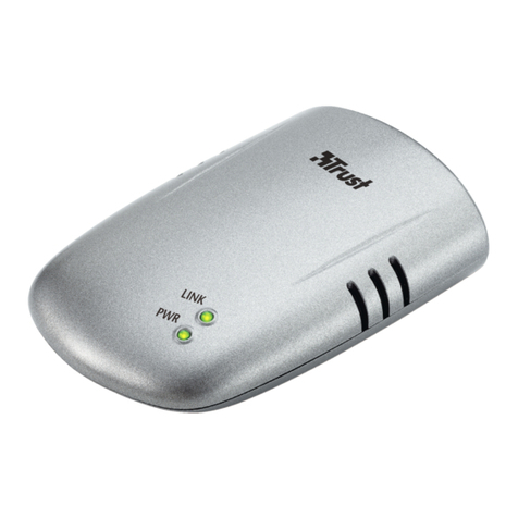
Cinterion Netkom XT65 User manual

Netkom XT65
User Guide
Copyright © Netkom Sp. z o.o. All rights reserved
Cinterion
wireless modules by embedded


3
Copyright © Netkom Sp. z o.o. All rights reserved
Safety information
Radio devices have limitations in the
vicinity of electronic devices:
When in hospitals or other health care•
facilities, observe the restrictions on the
use of mobiles. Switch off the cellular
terminal or mobile if to be instructed
to do so by the guidelines posted in
sensitive areas. Medical equipment may
be sensitive to RF energy.
Switch the Terminal off when flying.•
Secure it so that it cannot be switched
on inadvertently.
Do not operate the cellular terminal or•
mobile in the presence of flammable
gases or fumes. Operation of any
electrical equipment in potentially
explosive atmospheres can constitute a
safety hazard.
Interference can occur if the device is•
used near televisions, radios or PCs.
In order to avoid possible damage,•
we recommend that you only use the
specified accessories.These have been
tested and shown to work well with the
Terminal. However, the warranty does
not cover these accessories.
The warranty does not apply in the
event of improper use.

4Copyright © Netkom Sp. z o.o. All rights reserved
Contents
Safety information..............................................3
Contents................................................................4
Front view .................................................. 6
Rear view ................................................... 6
Overview...............................................................6
Product description............................................7
Highlights................................................... 8
Applications ............................................... 8
Interfaces................................................... 8
Highlights................................................... 9
SMS ........................................................... 9
Certification................................................ 9
Features................................................................9
Data ......................................................... 10
Fax............................................................ 10
Supplementary services .......................... 10
External interfaces................................... 10
Accessories.............................................. 10
Package contents / scope of delivery.......11
Safety and installation information ..........11
Installation..........................................................11
DIN rail installation .................................. 12
IO interface .............................................. 13
Interface description .......................................13
IO Interface Connector............................. 14
Power supply............................................ 17
Programmable outputs ............................ 18
Inputs ....................................................... 19
Analog input............................................. 20
Serial interface......................................... 22

5
Copyright © Netkom Sp. z o.o. All rights reserved
Contents
I2C interface............................................. 24
1-Wire interface....................................... 26
VDD supply .............................................. 27
Reset and watchdog............................... 28
Watchdog ................................................ 29
GSM antenna connector FME ................. 35
GPS antenna connector SMA.................. 37
GSM status LED ...................................... 39
Programmable LED .................................. 41
Hardware settings ................................... 42
Switching on/off terminal ........................ 44
Startup ................................................................44
AT command control................................ 45
SW update............................................... 45
Firmware.............................................................45
Maintenance tips..................................... 46
Certification.............................................. 46
Certification / maintenance............................46

6Copyright © Netkom Sp. z o.o. All rights reserved
Overview
Front view
Rear view
SIM card
reader
18-PIN
connector
Antenna
connectors
LEDs display
Reset

7
Copyright © Netkom Sp. z o.o. All rights reserved
Product description
The heart of this modern
compact modem is a Java™
programmable GSM and GPS modem. It
will send current state and GPS position
of the logistic unit via SMS or GPRS.
An integration in a VPN network is
possible too.The competed price of GPRS
data transfer with known quality gives
users advantage to be always connected.
Why Netkom XT65?
This device is a build for join
between the GPS technology and the
logistic management.
The Netkom XT65 gives an ideal solution
for transporting and logistic company.
The XT65 it’s an excellent
ingredient which joins the feature of
Java and the german excellence of
Cinterion(Siemens).

8Copyright © Netkom Sp. z o.o. All rights reserved
Product description
Quad-band GSM 850/900/1800/1900•
GPRS multi-slot class 12•
Output Power: Class4 / Class 1•
SIM via GSM or GPRS•
SIM application tool kit•
JAVA included•
Highlights
Applications
Interfaces GSM antenna: SMA/FME connector•
GPS antenna: SMA connector•
Reset button•
4-pole Western plug (female) for audio•
accessory
18 pin Micro-N-Lok connector:•
- 1 x analog in (ADC) with selectable
(GPIO) range
- Vout (3V)
- 4 x digital inputs Vin<30V
(3 x active high, 1 x active low)
- 2 x output OC
- 1 x RS232 serial interface
(RXD,TXD,RTS,CTS )
- I2C interface
- 1-wire interface
- Power supply
SIM card interface 3V, 1.8V•
Operating status LED:•
- for GSM/ GPRS
Control LED(programmable)•
Micro-switch for select peripheral•
devices (only for advanced users)
Logistic monitoring•
Remote monitoring•
Remote meter reading•

9
Copyright © Netkom Sp. z o.o. All rights reserved
Features
Highlights
SMS
Quad-band 850/900/1800/1900 MHz•
CE certificate•
JAVA included•
Dimensions(WxDxH): 76x55x30•
Weight: 143•
Ambient temperature range: -25•
SMS cell broadcast•
Text and PDU mode•
Transmission of SMS alternatively over•
CSD or GPRS

10 Copyright © Netkom Sp. z o.o. All rights reserved
Features
GPRS: max. 86 kbps DL & UL•
Coding scheme CS 1, 2, 3, 4•
PBCCH support•
CSD up to 14.4 kbps•
USSD support•
Non-transparent mode•
V.110•
Data
Fax Group 3, class 1•
Supplementary
services
Phone book•
Multiparty•
External interfaces 18-pin Mocro-N-Lok connector•
SIM card holder•
GPS antenna connector SMA•
GSM antenna connector FME•
Accessories Antenna GSM, Antenna GPS, SIM cards

11
Copyright © Netkom Sp. z o.o. All rights reserved
Installation
Netkom XT65 terminal
Package unit:
Netkom XT65 terminal•
Optional accesories*:
Antenna•
GPS-
GSM-
Package contents /
scope of delivery
Safety and
installation
information
Connect a fast 1.25 A fuse to the•
incoming line for the positive supply
voltage to protect the modem.
If a power supply unit is used to supply•
the modem, it must meet the demands
placed on SELV circuits in accordance
with EN60950. When using batteries
and accumulators, adhere to the
relevant regulations.
The maximum permissible connection•
length between the modem and the
supply source is 3 m.
Your supplier will be pleased to•
provide you with a detailed technical
description and technical support for
the Cinterion modem.
*In order to avoid possible damage, we recommend that you
only use the specified and proven accessories.

12 Copyright © Netkom Sp. z o.o. All rights reserved
Installation
DIN rail
installation
The terminal can be mounted on DIN rail
with optional clips.

13
Copyright © Netkom Sp. z o.o. All rights reserved
Interface description
The following interfaces are available on
the modem:
18-pin Micro-N-Lok connector•
SIM card holder•
GSM antenna connector FME•
GPS antenna connector SMA•
Via the IO interface connector the
following interfaces and functions are
provided:
•Programmableoutputs
•Inputs
•Oneanaloginput
•Serialinterface(ASC0)
•Powersupply
IO interface

14 Copyright © Netkom Sp. z o.o. All rights reserved
This chapter provides specifications for
the 18-pin IO interface connector which
serves the outputs, inputs and power
supply interfaces of theTerminal. The
type of the receptacle assembled on the
Netkom XT65 terminal is Micro Mate-N-
LOK 3mm from Tyco Electronics. Mating
headers can be chosen from the Tyco
Micro Mate-N-LOK Series. For latest
product information please contact your
Micro Electronics dealer or visit the Tyco
home page, for example:
http://www.tycoelectronics.com
IO Interface
Connector
Tyco Micro Mate-N-LOK series on the
Netkom XT65 Terminal
Interface description

15
Copyright © Netkom Sp. z o.o. All rights reserved
Receptacle contact forTyco Micro
Mate-N-LOK series
Interface description
Mating connectorTyco Micro Mate-
NLOK series

16 Copyright © Netkom Sp. z o.o. All rights reserved
Parameter Specification
Number of contacts 18
Voltage rating 250V 250V
Current rating 5A max. 5A max
Resistance 0.02 Ohm max. per contact
Dielectric withstanding
voltage
1500VAC
Operating temperature - 40°C ... +105°C
Contact centerline 3.0mm
Mating force 6.67N max. per contact
Receptacle housing material Flame-retardant black
thermoplastic
Contact material Phosphor bronze
Interface description

17
Copyright © Netkom Sp. z o.o. All rights reserved
Pin number Function
9 GND
18 POWER
Power supply
Locations of power supply pins
Interface description
The power supply of the Netkom XT65
Terminal has to be a single voltage
source of POWER = 8V…30V capable
of providing a peak during an active
transmission.The uplink burst causes
strong ripples (drop) on the power lines.
The Netkom XT65 terminal is protected
from supply voltage reversal and
overvoltage.
A fast acting fuse I≥0.8A with melting
integral I²t (0.8 … 1.5 A²s) is necessary to
use the Netkom XT65Terminal at a 24V
power supply system for vehicles.
The power supply must be compliant with
the EN60950 guidelines.

18 Copyright © Netkom Sp. z o.o. All rights reserved
Interface description
Programmable
outputs
The terminal has two programmable type
OC outputs.
Attention!
High GPIO level is equal low level on the
terminal’s output and the same way back.
Locations of programmable outputs
pins
Pin
number Function GPIO
1 OUT1 GPIO8
2 OUT2 GPIN5
9 GND
14 GND*
*recommended

19
Copyright © Netkom Sp. z o.o. All rights reserved
Interface description
Inputs
Locations of inputs pins
The terminal has four inputs.
Pin
number Function GPIO Active level
3 IN1 GPIO 6 LOW
4 IN2 GPIO 7 HIGH
5 IN3 GPIO 9 HIGH
6 IN4 GPIO 10 HIGH
9 GND
14 GND*
*recommended

20 Copyright © Netkom Sp. z o.o. All rights reserved
Analog input
Location of analog input pins
Second analog input (ADC2) is internally
connected to power supply.
Interface description
Pin
number Function GPIO
7 ADC ADC1
9 GND
14 GND
*recommended
Table of contents
