Circadiance SmartMonitor2 Reference guide
Checkout Procedure Manual
1020818 REV1 SmartMonitor2 Checkout Procedure

© 2015 Circadiance LLC. All rights reserved.

SmartMonitor® 2 Checkout Procedure Manual
Page 1
Table of Contents
Introduction...........................................................................................................................................2
Required Equipment..............................................................................................................................2
Important Notes…Read Carefully.........................................................................................................3
Establishing Initial Alarm Set Points....................................................................................................3
The Functional Self-Test.......................................................................................................................5
Checkout Set-up....................................................................................................................................6
Verification of Respiration Signal Sensitivity for SmartMonitor 2.......................................................7
Verification of the ECG Signal Sensitivity for SmartMonitor 2............................................................9
Verification of the Apnea Alarm and Delay ........................................................................................11
Verification of the Low Breath Rate Alarm.........................................................................................11
Verification of the Low and High Heart Alarms..................................................................................13
Verification of Cardiogenic Artifact Rejection....................................................................................14
Verification of Loose Connection Alarm ............................................................................................14
Verification of Accidental Power-off Alarm (Sibling Alarm) ..............................................................15
Operational Verification of the Main Battery Pack.............................................................................15
Clock Chip Battery ..............................................................................................................................15
Watchdog Test.....................................................................................................................................16
Transferring SmartMonitor 2 data to a Memory Card ........................................................................17
Computer Retrieval of SmartMonitor 2 Data ......................................................................................18
Clear Memory.......................................................................................................................................18
Circadiance SmartMonitor 2 Apnea Monitor Verification Checklist..................................................19

SmartMonitor® 2 Checkout Procedure Manual
Page 2
INTRODUCTION
This manual provides procedures to determine if the Circadiance Model 4000 series SmartMonitor 2 and
its accessories are suitable for use in patient applications. These procedures require the use of a
calibrated Model 5000 Simulator or a Fluke Biomedical ProSim™ 2 Simulator, which is the source of ECG
and respiratory test signals. No other simulators are acceptable for use while performing these
procedures.
This manual is for performance testing and is not intended as a service or repair guide. The procedures
contained in this manual are to be performed between each patient use or every 6-12 months. Monitors
that have been used in a home environment should always be tested between patients. Operational
information for the SmartMonitor 2 can be found in the Professional Operator’s Manual.
The SmartMonitor 2 must perform within the specifications of the procedures in this manual before use on
patients.
REQUIRED EQUIPMENT
Model 4000 series SmartMonitor 2
Model 5000 ECG/Respiration Simulator or Fluke Biomedical ProSim™ 2 Simulator
Model 9520-1 Safety Lead Wires
Model 4005 Patient Cable
Model 990 Remote Alarm (optional)
Stopwatch
PCMCIA Memory Card

SmartMonitor® 2 Checkout Procedure Manual
Page 3
IMPORTANT NOTES…READ CAREFULLY
As the checkout procedure is being performed, please remember the following:
Complete all checkout procedures in one continuous operation and in the order presented in this
manual. If you have not performed the checkout procedure before, please read and understand this
manual before starting the checkout procedure.
Do not place the SmartMonitor 2 or the simulator near electrical appliances that could cause
interference (i.e., cordless or cellular telephones, air conditioners, vaporizers, computers, TVs, VCRs,
microwave ovens, etc.)
Coiling and/or manipulation of the patient cable or lead wires should be minimized.
Once changes are made on the simulator, do not maintain hand contact with the simulator knobs or
enclosure. It may affect the ECG and respiration signals.
Because the signal from the simulator is interrupted by each change in the simulator setting, allow
approximately ten seconds after each setting change for the monitor circuitry to stabilize.
In the section of Establishing Initial Alarm Set Points of the checkout procedure, the changes to the
alarm parameters of the SmartMonitor 2 should be made through the menu display located on the
bottom panel of the SmartMonitor 2
The 5000 Simulator will not function correctly if the 9-volt battery is low. It should be replaced,
minimally, once per month or more often with heavy use. The battery voltage can be too low for
calibrated output signals before activation of the LOW BATTERY light.
The SmartMonitor 2’s memory should be cleared before performing the checkout procedures.
The 990 Remote Alarm may be verified throughout the checkout procedures. The Remote Alarm will
not function correctly if the 9-volt battery is low. It should be replaced, minimally, once per month or
more often with heavy use.
ESTABLISHING INITIAL ALARM SET POINTS
1. Remove the Menu Display Cover from the bottom of the SmartMonitor 2. Note the three buttons to
the right of the LCD display - UP arrow button, the DOWN arrow button, and the ENTER button.
2. Access the Menu Mode for the SmartMonitor 2 as follows:
a. Press the POWER button ON.
b. Within ten seconds, enter the following key code:
c. Press the DOWN arrow once,
d. Press the UP arrow twice,
e. Press the ENTER button three times.
NOTE
While in Menu Mode, the SmartMonitor 2 will beep every 10 seconds.
This is to remind you that the SmartMonitor 2 is not monitoring and
to power off the SmartMonitor 2 after parameters are set.

SmartMonitor® 2 Checkout Procedure Manual
Page 4
3. To set a specific parameter or series of parameters:
a. Use the UP arrow button to move forward to the parameter to be changed.
b. Select the parameter to be changed by pressing the ENTER key – this will cause the current
value to flash.
c. The value can be increased by pressing the UP arrow button and decreased by pressing the
DOWN arrow button.
d. To select the displayed value, press the ENTER button. The value displayed will continue to
flash until you press the ENTER button.
e. Press the UP arrow button to proceed to the next parameter to be selected.
f. Press the UP arrow to display CLEAR MEMORY? then clear the memory.
4. For this checkout procedure, set the SmartMonitor 2 parameters as follows:
Table 1
Parameter
Value
Parameter
Value
Patient Name
Test
Record Heart Rate
YES
Patient ID Number
1234
Record ECG
YES
STD Alarm Parameters
Are Selected
Record Auxiliary 1
OFF
STD Record Parms
Not Selected
Record Auxiliary 2
OFF
STD System Parms
Not Selected
Record Auxiliary 3
OFF
Apnea Alarm
20 Seconds
Record Auxiliary 4
OFF
Low Breath Rate Alarm
0FF
External Physiological Trigger
OFF
Bradycardia Alarm
80 BPM
External Equipment Trigger
OFF
Bradycardia Alarm Delay
0 seconds
Date
Current Date
Tachycardia Alarm
230 BPM
Time
Current Time
Tachy Alarm Delay
5 Seconds
Rate Display
ON
Record Mode
EVENT
Phone Number For Computer
(___-____)
Apnea for Record
16 Seconds
Time to Call the Computer
(__/__/__ __:__)
Brady Limit Record
OFF
Dial if Memory Is Full
NO
Pre/Post Time
30/15
Move Data to Card
NO
Record Impedance?
YES
Memory Status
0 Percent Full
Record Respiration Rate
YES
Clear Memory
NO
NOTE
To change STD Record Parameters to not selected, you must set the
Apnea for Record parameter to 18 seconds.
5. After the designated checkout parameters are entered, turn the SmartMonitor 2 off using the proper
Power-off procedure. The proper power-off procedure is as follows:
a. Press and hold the RESET button.
b. Press and release the POWER button.
c. Wait two seconds then release the RESET button.

SmartMonitor® 2 Checkout Procedure Manual
Page 5
THE FUNCTIONAL SELF-TEST
1. Plug the Battery Charger into a grounded, live wall outlet and connect the other end into the
receptacle on the back of the SmartMonitor 2 Labeled DC POWER. The CHARGER light on the front
of the SmartMonitor 2 should light and remain on continuously.
2. Insert the patient cable into the receptacle labeled Patient Input on the front of the SmartMonitor 2.
3. Insert the WHITE lead (RA) wire into the “RA” socket of the patient cable. Insert the BLACK lead wire
into the “LA” socket of the patient cable. Make sure that both lead wires are fully inserted into the
color-coded sockets of the patient cable.
4. Connect the lead wires to the Functional Self-Test receptacles on the right side of the SmartMonitor
2. Insert the pin end of the WHITE lead wire into the receptacle labeled “RA”. Insert the pin end of
the BLACK lead wire into the receptacle labeled “LA”.
5. If you are using the Remote Alarm, connect it to the REMOTE ALARM output on the back of the
Monitor at this time. Turn the Remote Alarm power to the on position. Each time the Monitor Alarms,
verify that the sound can be heard through the Remote Alarm and that the Monitor light on the
Remote Alarm comes on.
NOTE
When using a stopwatch, timing should begin after the power button has been pressed.
6. Press the POWER button to turn the SmartMonitor 2 on. The alarm should beep and all the lights
should come on for approximately 4 seconds. After all the alarm lights turn off, the CHARGER and
POWER light should remain on and within 15 seconds, the green HEART and RESPIRATION light
should be blinking. The lights will continue to flash for about 45 seconds.
NOTE
If the following lights remain on or are blinking, and/or the alarm sounds continuously,
corrective action should be taken before continuing the Checkout Procedure.
LOW BATTERY – The SmartMonitor 2 battery pack is discharged. Turn the SmartMonitor 2 off
using the correct power-off procedure (refer to pg. 4, step 5). Make sure the battery charger is
plugged into a live power outlet and properly connected to the SmartMonitor 2. Allow the
SmartMonitor 2 to recharge for 8 hours before performing the Checkout Procedure. This will
provide fully charged battery power.
FULL MEMORY – The SmartMonitor 2’s memory is 80% to 100% full. If the SmartMonitor 2 has
been used on patients, the memory should be transferred to a Memory Disk, then cleared using
the procedure described in the Professional Operator’s Manual.
LOOSE CONNECTION – Indicates loose or bad lead wires or patient cable. Check all
connections and/or replace lead wires first, then patient cable if necessary.
7. After approximately 45 seconds, the green HEART and RESPIRATION lights should stop blinking.
The red LOW HEART light should illuminate within approximately seven seconds after the HEART
light stops flashing, and the audible alarm should beep once every second.
8. Approximately 20 seconds after last Respiration detection, the Red Apnea light should illuminate.
(There should be no green HEART or RESPIRATION lights during this alarm.) When the APNEA
light illuminates, the Functional Self-test is complete.
9. Turn the Remote Alarm off.
10. Turn the SmartMonitor 2 off using the correct power-off procedure (refer to pg. 4, step 5). If the
SmartMonitor 2 is not powered off correctly, the “sibling” alarm will sound. Repeat the proper Power-
off procedure as described above until power is off.

SmartMonitor® 2 Checkout Procedure Manual
Page 6
CHECKOUT SET-UP
NOTE
The Battery Charger and the Patient Cable should remain connected to the
SmartMonitor 2, as they were in the Functional Self-Test.
1. Disconnect the lead wires from the Self-Test connectors of the SmartMonitor 2.
2. Connect the RA and LA leads to the simulator as follows:
a) For the Model 5000 simulator:
i. Loosen the binding post caps (labeled “RA” and “LA”) under THREE LEAD
ECG/RESP.
ii. Insert the white lead wire into the post-labeled “RA”. Insert the black lead wire into
the post-labeled “LA.” Tighten both post caps on the simulator.
b) For the Fluke ProSim™ 2 simulator, insert the leads into the RA and LA posts.
3. Set the simulator controls as follows:
Table 2
Control
Model 5000 Setting
Fluke ProSim™ 2 Setting
ECG Beats /Min
200
200
ECG AMPL / MV
0.5
0.5
RESP. Breaths / Min
10
15
Variation Ohms
0.5
0.5
Base Impedance Ohms
200
500
4. Turn the simulator POWER on.
5. Turn the SmartMonitor 2 power on and proceed to Verification of Respiration Signal Sensitivity.

SmartMonitor® 2 Checkout Procedure Manual
Page 7
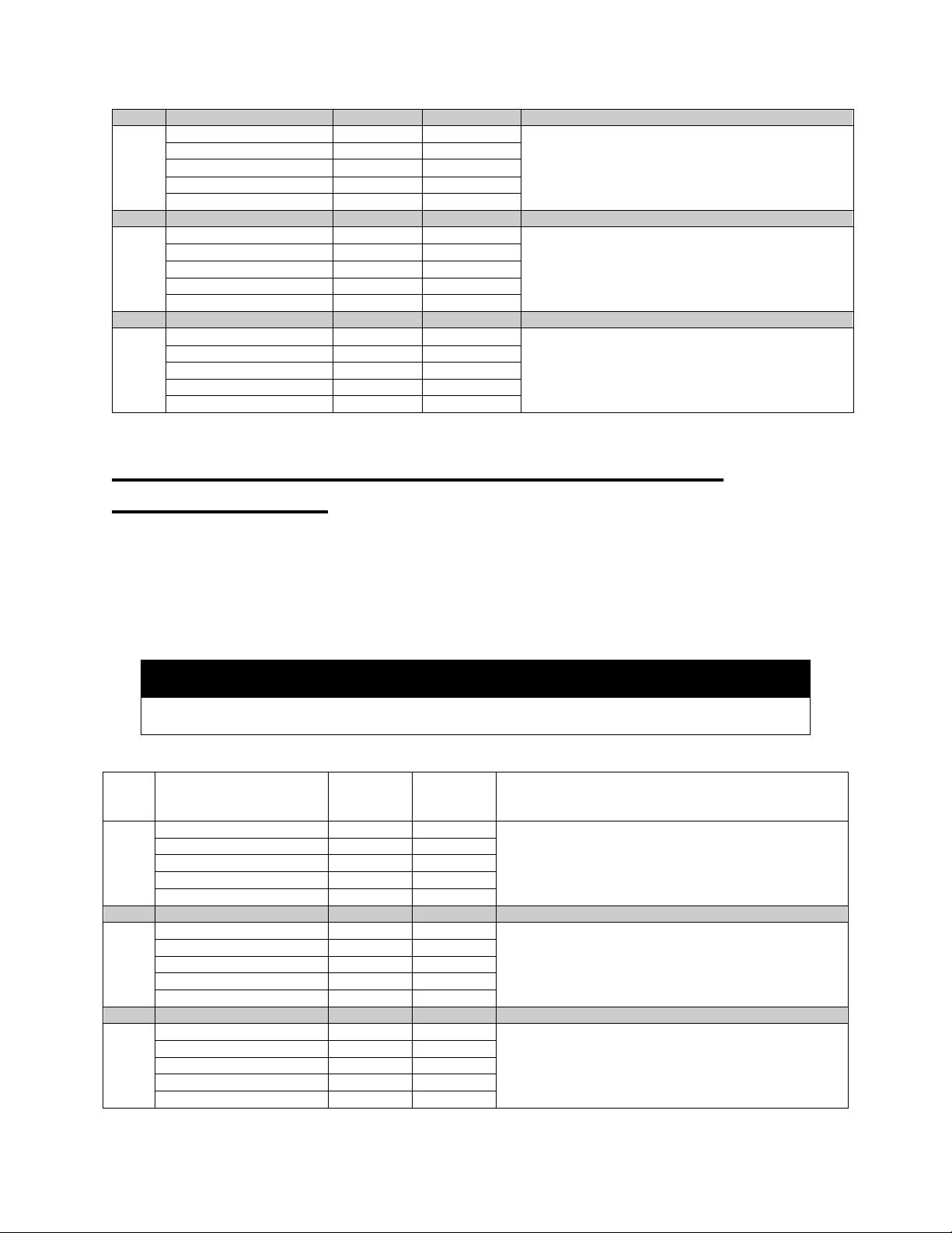
VERIFICATION OF RESPIRATION SIGNAL SENSITIVITY FOR
SMARTMONITOR 2
There are 17 test points that require different simulator settings. For each test point, make the required
changes as listed in Table 3 and verify the appropriate SmartMonitor 2 response. Simulator control
setting values that change from the previous Test Point are marked with an asterisk (*). Press the
RESET button on the SmartMonitor 2 to reset any alarm faults.
Note: The last three tests require a simulator setting of 150 breaths per minute, and can only be
performed when using the Model 5000 simulator, as indicated below.
NOTE
Apnea should occur approximately 20 seconds after last respiration detection.
Table 3
Test
Point
Simulator Control
Model
5000
Setting
Fluke
ProSim™ 2
Setting
Smart Monitor 2 Response
1
ECG BEATS/MIN.
200
200
No Alarms
100% Detection
ECG AMPLITUDE/MV.
0.5
0.5
Resp. Breath / MIN
10
15
Variation OHMS
0.5
0.5
Base Impedance Ohms
200
500
2
ECG BEATS/MIN.
200
200
No respiration detection
Apnea light should illuminate and audible alarm
should beep once per second 20 seconds (+/- 1)
ECG AMPLITUDE/MV.
0.5
0.5
Resp. Breath / MIN
10
15
Variation OHMS
0.1*
Apnea 22
seconds*
Base Impedance Ohms
200
500
3
ECG BEATS/MIN.
200
200
No alarms
100% Detection
Press Reset button to clear alarm faults and red
light.
ECG AMPLITUDE/MV.
0.5
0.5
Resp. Breath / MIN
15*
15*
Variation OHMS
0.5*
0.5*
Base Impedance Ohms
200
500
4
ECG BEATS/MIN.
200
200
No respiration detection
Apnea light should illuminate and audible alarm
should beep once per second 20 seconds (+/- 1)
ECG AMPLITUDE/MV.
0.5
0.5
Resp. Breath / MIN
15
15
Variation OHMS
0.1*
Apnea 22
seconds*
Base Impedance Ohms
200
500
5
ECG BEATS/MIN.
200
200
No alarms
100% Detection
Press Reset button to clear alarm faults and red
light.
ECG AMPLITUDE/MV.
0.5
0.5
Resp. Breath / MIN
30*
30*
Variation OHMS
0.2*
0.2*
Base Impedance Ohms
200
500

SmartMonitor® 2 Checkout Procedure Manual
Page 8
6
ECG BEATS/MIN.
200
200
No respiration detection
Apnea light should illuminate and audible alarm
should beep once per second 20 seconds (+/- 1)
after last respiration is detected.
ECG AMPLITUDE/MV.
0.5
0.5
Resp. Breath / MIN
30
30
Variation OHMS
0.1*
Apnea 22
seconds*
Base Impedance Ohms
200
500
7
ECG BEATS/MIN.
200
200
No alarms
100% Detection
Press Reset button to clear alarm faults and red
light.
ECG AMPLITUDE/MV.
0.5
0.5
Resp. Breath / MIN
50*
60*
Variation OHMS
0.2*
0.2*
Base Impedance Ohms
200
500
8
ECG BEATS/MIN.
200
200
No respiration detection
Apnea light should illuminate and audible alarm
should beep once per second 20 seconds (+/- 1)
ECG AMPLITUDE/MV.
0.5
0.5
Resp. Breath / MIN
50
40
Variation OHMS
0.1*
Apnea 22
seconds*
Base Impedance Ohms
200
500
9
ECG BEATS/MIN.
200
200
No alarms
100% Detection
Press Reset button to clear alarm faults and red
light.
ECG AMPLITUDE/MV.
0.5
0.5
Resp. Breath / MIN
75*
80*
Variation OHMS
0.5*
0.5*
Base Impedance Ohms
200
500
10
ECG BEATS/MIN.
200
200
No respiration detection
Apnea light should illuminate and audible alarm
should beep once per second 20 seconds (+/- 1)
ECG AMPLITUDE/MV.
0.5
0.5
Resp. Breath / MIN
75
80
Variation OHMS
0.1*
Apnea 22
seconds*
Base Impedance Ohms
200
500
11
ECG BEATS/MIN.
200
200
No alarms
100% Detection
Press Reset button to clear alarm faults and red
light.
ECG AMPLITUDE/MV.
0.5
0.5
Resp. Breath / MIN
100*
100*
Variation OHMS
0.5*
0.5*
Base Impedance Ohms
200
500
12
ECG BEATS/MIN.
200
200
No respiration detection
Apnea light should illuminate and audible alarm
should beep once per second 20 seconds (+/- 1)
ECG AMPLITUDE/MV.
0.5
0.5
Resp. Breath / MIN
100
100
Variation OHMS
0.1*
Apnea 22
seconds*
Base Impedance Ohms
200
500
13
ECG BEATS/MIN.
200
200
No alarms
100% Detection
Press Reset button to clear alarm faults and red
light.
ECG AMPLITUDE/MV.
0.5
0.5
Resp. Breath / MIN
120*
120*
Variation OHMS
1*
1*
Base Impedance Ohms
200
500
14
ECG BEATS/MIN.
200
200
No respiration detection
Apnea light should illuminate and audible alarm
should beep once per second 20 seconds (+/- 1)
ECG AMPLITUDE/MV.
0.5
0.5
Resp. Breath / MIN
120
120
Variation OHMS
0.1*
Apnea 22
seconds*
Base Impedance Ohms
200
500
SmartMonitor® 2 Checkout Procedure Manual
Page 9
15
ECG BEATS/MIN.
200
-
No alarms
100% Detection
Press Reset button to clear alarm faults and red
light.
(Test case applicable only to the Model 5000)
ECG AMPLITUDE/MV.
0.5
-
Resp. Breath / MIN
150*
-
Variation OHMS
2*
-
Base Impedance Ohms
200
-
16
ECG BEATS/MIN.
200
-
No respiration detection
Apnea light should illuminate and audible alarm
should beep once per second 20 seconds (+/- 1)
after last respiration is detected.
(Test case applicable only to the Model 5000)
ECG AMPLITUDE/MV.
0.5
-
Resp. Breath / MIN
150
-
Variation OHMS
0.2*
-
Base Impedance Ohms
200
-
17
ECG BEATS/MIN.
200
-
No alarms
100% Detection
Press Reset button to clear alarm faults and red
light.
(Test case applicable only to the Model 5000)
ECG AMPLITUDE/MV.
0.5
-
Resp. Breath / MIN
150
-
Variation OHMS
2*
-
Base Impedance Ohms
200
-
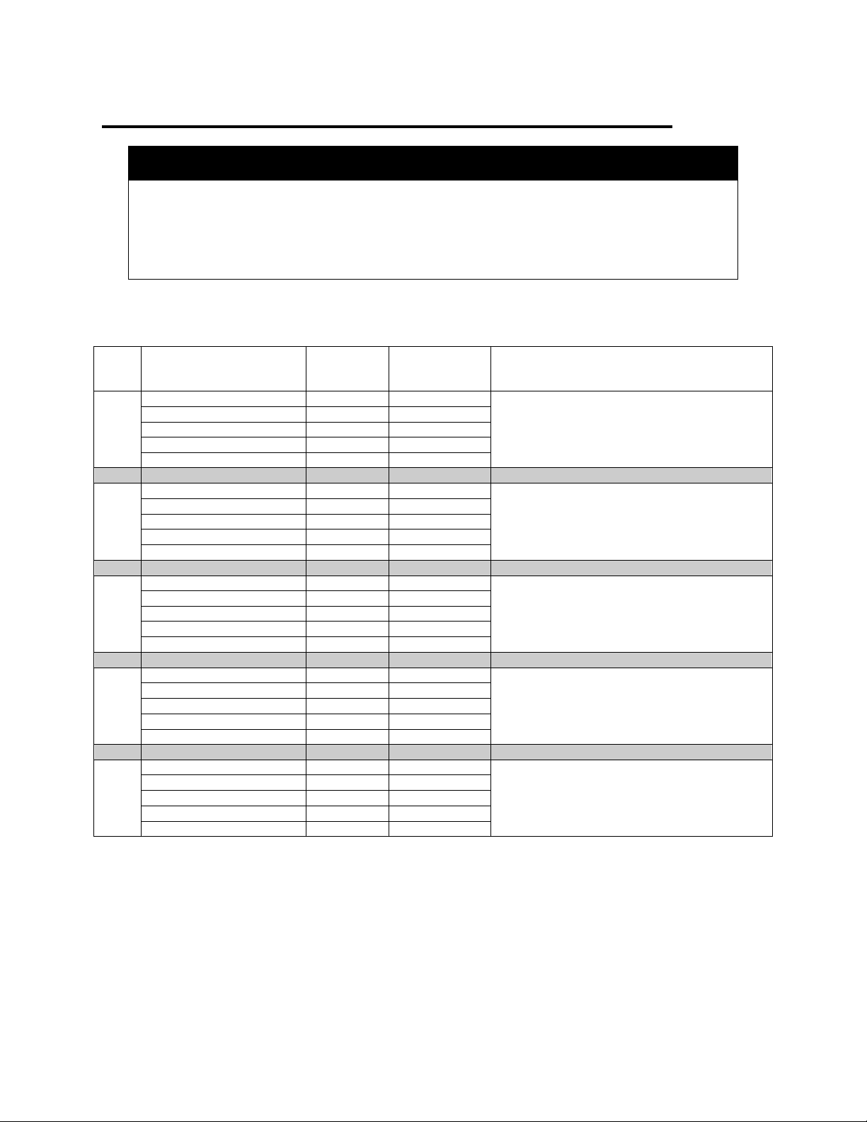
VERIFICATION OF THE ECG SIGNAL SENSITIVITY FOR
SMARTMONITOR 2
There are 12 test points that require different simulator settings. For each test point, make the required
changes as listed in Table 4 and verify the appropriate SmartMonitor 2 response. Simulator control
setting values that change from the previous Test Point are marked with an asterisk (*). Press the
RESET button on the SmartMonitor 2 to reset any alarm faults.
NOTE
Apnea should occur approximately 20 seconds after last respiration detection.
Table 4
Test
Point
Simulator Control
Model
5000
Setting
Fluke
ProSim™
2 Setting
Smart Monitor 2 Response
1
ECG BEATS/MIN.
25
30
100% Detections
Low heart light should illuminate and audible alarm
should beep once per second.
ECG AMPLITUDE/MV.
0.2
0.3
Resp. Breath / MIN
15
15
Variation OHMS
1
1
Base Impedance Ohms
200
500
2
ECG BEATS/MIN.
85*
90*
100% Detections
Audible alarm should stop. Press Reset to reset Low
Heart light.
ECG AMPLITUDE/MV.
0.2
0.3
Resp. Breath / MIN
15
15
Variation OHMS
1
1
Base Impedance Ohms
200
500
3
ECG BEATS/MIN.
85
90
No ECG Detections
Low heart light should illuminate and audible alarm
should beep once per second.
ECG AMPLITUDE/MV.
0.1*
0.1*
Resp. Breath / MIN
15
15
Variation OHMS
1
1
Base Impedance Ohms
200
500

SmartMonitor® 2 Checkout Procedure Manual
Page 10
4
ECG BEATS/MIN.
100*
100*
100% Detections
Audible alarm should stop. Press Reset to reset Low
Heart light.
ECG AMPLITUDE/MV.
0.2*
0.3*
Resp. Breath / MIN
15
15
Variation OHMS
1
1
Base Impedance Ohms
200
500
5
ECG BEATS/MIN.
100
100
No ECG Detections
Low Heart light should illuminate and audible alarm
should beep once per second.
ECG AMPLITUDE/MV.
0.1*
0.1*
Resp. Breath / MIN
15
15
Variation OHMS
1
1
Base Impedance Ohms
200
500
6
ECG BEATS/MIN.
150*
140*
100% Detections
Audible alarm should stop. Press Reset to reset Low
Heart light.
ECG AMPLITUDE/MV.
0.2*
0.3*
Resp. Breath / MIN
15
15
Variation OHMS
1
1
Base Impedance Ohms
200
500
7
ECG BEATS/MIN.
150
140
No ECG Detections
Low Heart light should illuminate and audible alarm
should beep once per second.
ECG AMPLITUDE/MV.
0.1*
0.1*
Resp. Breath / MIN
15
15
Variation OHMS
1
1
Base Impedance Ohms
200
500
8
ECG BEATS/MIN.
200*
200*
100% Detections
Audible alarm should stop. Press Reset to reset Low
Heart light.
ECG AMPLITUDE/MV.
0.5*
0.5*
Resp. Breath / MIN
15
15
Variation OHMS
1
1
Base Impedance Ohms
200
500
9
ECG BEATS/MIN.
200
200
No ECG Detections
Low Heart light should illuminate and audible alarm
should beep once per second.
ECG AMPLITUDE/MV.
0.1*
0.1*
Resp. Breath / MIN
15
15
Variation OHMS
1
1
Base Impedance Ohms
200
500
10
ECG BEATS/MIN.
240*
240*
100% Detections
Press Reset to reset Low Heart light. High Heart
light should illuminate and audible alarm should beep
Twice per second.
ECG AMPLITUDE/MV.
0.5*
0.5*
Resp. Breath / MIN
15
15
Variation OHMS
1
1
Base Impedance Ohms
200
500
11
ECG BEATS/MIN.
240
240
No ECG Detections
Low Heart light should illuminate and audible alarm
should beep once per second.
ECG AMPLITUDE/MV.
0.1*
0.1*
Resp. Breath / MIN
15
15
Variation OHMS
1
1
Base Impedance Ohms
200
500
12
ECG BEATS/MIN.
200*
200*
100% Detection
Press Reset button to reset High and Low Heart.
ECG AMPLITUDE/MV.
0.5*
0.5*
Resp. Breath / MIN
15
15
Variation OHMS
1
1
Base Impedance Ohms
200
500

SmartMonitor® 2 Checkout Procedure Manual
Page 11
VERIFICATION OF THE APNEA ALARM AND DELAY
There are 3 test points that require different simulator settings. For each test point, make the required
changes as listed in Table 5 and verify the appropriate SmartMonitor 2 response. Simulator Control
setting values that change from the previous Test Point are marked with an asterisk (*). Press the
RESET button on the SmartMonitor 2 to reset any alarm faults.
Table 5
Test
Point
Simulator Control
Model 5000
Setting
Fluke
ProSim™ 2
Setting
Smart Monitor 2 Response
1
ECG BEATS/MIN.
200
200
No Alarms
100% Detections
ECG AMPLITUDE/MV.
0.5
0.5
Resp. Breath / MIN
15
15
Variation OHMS
1
1
Base Impedance Ohms
200
500
2
ECG BEATS/MIN.
200
200
No respiration detection
Apnea light should illuminate and audible alarm
should beep once per second
20 seconds (+/- 1)
ECG AMPLITUDE/MV.
0.5
0.5
Resp. Breath / MIN
15
15
Variation OHMS
0.1*
Apnea 22
seconds*
Base Impedance Ohms
200
500
3
ECG BEATS/MIN.
200
200
100% Detection
Press Reset button to clear alarm faults and red
light.
ECG AMPLITUDE/MV.
0.5
0.5
Resp. Breath / MIN
15
15
Variation OHMS
0.5*
0.5*
Base Impedance Ohms
200
500
VERIFICATION OF THE LOW BREATH RATE ALARM
1. Turn the SmartMonitor 2 off as follows:
a. Press and hold the RESET button.
b. Press and release the POWER button.
c. Wait two seconds then release the RESET button.
2. Access the Menu Mode for the SmartMonitor 2 as follows:
a. Press the POWER button ON.
b. Within ten seconds, enter the following key code:
c. Press the DOWN arrow once,
d. Press the UP arrow twice,
e. Press the ENTER button three times.
3. Change the entry for LOW BREATH ALARM from OFF to 16 BrPM for the Model 5000 or
18 BrPM for the Fluke ProSim™ 2 Simulator.
4. In order for the SmartMonitor 2 to accept the parameter value changes, turn the SmartMonitor 2 off
as described in step 1 above.
5. Set the simulator controls as shown in Test Point 1 in Table 6.

SmartMonitor® 2 Checkout Procedure Manual
Page 12
6. Power on the SmartMonitor 2.
7. Test the SmartMonitor per Table 6.
Table 6
Test
Point
Simulator Control
Model 5000
Setting
Fluke
ProSim™
2 Setting
Smart Monitor 2 Response
1
ECG BEATS/MIN.
100*
100*
No Alarms
100% Detections
ECG
AMPLITUDE/MV.
0.5
0.5
Resp. Breath / MIN
30*
30*
Variation OHMS
1*
1*
Base Impedance
Ohms
200
500
2
ECG BEATS/MIN.
100
100
No respiration detection
Apnea light should illuminate and audible alarm
should beep once per second
20 seconds (+/- 1)
ECG
AMPLITUDE/MV.
0.5
0.5
Resp. Breath / MIN
10*
15*
Variation OHMS
1
1
Base Impedance
Ohms
200
500
3
ECG BEATS/MIN.
100
100
The audible alarm should stop within approximately 7
seconds, but the Apnea light should remain flashing.
Press Reset button to clear alarm and faults.
ECG
AMPLITUDE/MV.
0.5
0.5
Resp. Breath / MIN
30*
30*
Variation OHMS
1
1
Base Impedance
Ohms
200
500
8. Turn the SmartMonitor 2 off as described in step 1 above.
9. Access the Menu Mode for the SmartMonitor 2 as described in step 2 above.
10. Change the setting for LOW BREATH ALARM to OFF.
11. Turn the SmartMonitor 2 off as described in step 1 above.
12. Power on the SmartMonitor 2. (The SmartMonitor 2 must be powered off and then on for the
changed parameter values to be accepted.)
SmartMonitor® 2 Checkout Procedure Manual
Page 13
VERIFICATION OF THE LOW AND HIGH HEART ALARMS
NOTE
Due to large signal changes that result when simulator settings are initially changed,
the off-scale signal recognition circuitry of the SmartMonitor 2 may activate and cause
brief pauses in detection, once the
normal signal is detected by the monitor. This
would allow an additional 10 seconds for the circuitry to stabilize before proceeding
with verifying the operation of the SmartMonitor 2.
Table 7
Test
Point
Simulator Control
Model
5000
Setting
Fluke
ProSim™ 2
Setting
Smart Monitor 2 Response
1
ECG BEATS/MIN.
85*
90*
No Alarms
100% Detections
ECG AMPLITUDE/MV.
0.5
0.5
Resp. Breath / MIN
30
30
Variation OHMS
1
1
Base Impedance Ohms
200
500
2
ECG BEATS/MIN.
75*
60*
Red Low Heart light should illuminate and
audible alarm should sound once per second.
Green Respiration should flash.
ECG AMPLITUDE/MV.
0.5
0.5
Resp. Breath / MIN
30
30
Variation OHMS
1
1
Base Impedance Ohms
200
500
3
ECG BEATS/MIN.
85*
90*
The audible alarm will stop and the red Low
Heart light will remain on.
Press Reset button to Low Heart light
ECG AMPLITUDE/MV.
0.5
0.5
Resp. Breath / MIN
30
30
Variation OHMS
1
1
Base Impedance Ohms
200
500
4
ECG BEATS/MIN.
240*
240*
Red High Heart light should illuminate and the
audible alarm should beep twice per second.
ECG AMPLITUDE/MV.
0.5
0.5
Resp. Breath / MIN
30
30
Variation OHMS
1
1
Base Impedance Ohms
200
500
5
ECG BEATS/MIN.
200*
200*
The audible alarm will stop and the red High
Heart light will remain on.
Press Reset button to High Heart light.
ECG AMPLITUDE/MV.
0.5
0.5
Resp. Breath / MIN
30
30
Variation OHMS
1
1
Base Impedance Ohms
200
500

SmartMonitor® 2 Checkout Procedure Manual
Page 14
VERIFICATION OF CARDIOGENIC ARTIFACT REJECTION
Table 8
Test
Point
Simulator Control
Model 5000
Setting
Fluke
ProSim™ 2
Setting
Smart Monitor 2 Response
1
ECG BEATS/MIN.
100*
100*
No Alarms
100% Detections
ECG AMPLITUDE/MV.
0.5
0.5
Resp. Breath / MIN
30
30
Variation OHMS
1
1
Base Impedance Ohms
200
500
2
ECG BEATS/MIN.
100
100
No respiration detection
Apnea light should illuminate and audible
alarm should beep once per second 20
seconds (+/- 1) after last respiration is
detected.
ECG AMPLITUDE/MV.
0.5
0.5
Resp. Breath / MIN
100*
100*
Variation OHMS
1
1
Base Impedance Ohms
200
500
3
ECG BEATS/MIN.
100
100
100% Detection
Press Reset button to clear alarm faults and
red light.
ECG AMPLITUDE/MV.
0.5
0.5
Resp. Breath / MIN
75*
80*
Variation OHMS
1
1
Base Impedance Ohms
200
500
VERIFICATION OF LOOSE CONNECTION ALARM
NOTE
If a unit under test (UUT) emits an additional alarm during any of the steps in this test, where a
“No Alarm” condition should exist, verify that the UUT has a good co
nnection with the
simulator. Once a good connection is confirmed, the audible alarm should stop. Press the
reset button on the UUT to clear the Loose Connection light. If the alarm condition clears,
resume testing at the next step. If the alarm condition continues, fail the UUT.
1. Disconnect the Patient Cable from the SmartMonitor 2. The audible alarm should sound continuously
and the LOOSE CONNECTION LIGHT should illuminate.
2. Reconnect the Patient Cable. The audible alarm should stop. Press the RESET button to reset the
LOOSE CONNECTION LIGHT. The GREEN HEART LIGHT and GREEN RESPIRATION LIGHT
should resume flashing.
3. Disconnect the White Lead Wire from the simulator. The audible alarm should sound continuously
and the LOOSE CONNECTION LIGHT should come on. Reconnect the White Lead Wire. The
audible alarm should stop.
4. Press the RESET button to turn off the LOOSE CONNECTION LIGHT.
5. Disconnect the Black Lead Wire from the simulator. The audible alarm should sound continuously
and the LOOSE CONNECTION LIGHT should illuminate.
6. Reconnect the Black Lead Wire. The audible alarm should stop.
7. Press the RESET button to turn off the LOOSE CONNECTION LIGHT.
8. After reconnecting the lead wires, set the Base Impedance Ohms to 1.5K on the simulator. There
should be NO alarms.

SmartMonitor® 2 Checkout Procedure Manual
Page 15
Note: Perform steps 9-10 only with the Model 5000 simulator.
9. Change the Base Impedance Ohms to 2K. The audible alarm should sound continuously and the
LOOSE CONNECTION LIGHT should illuminate.
10. Change the Base Impedance Ohms back to 1.5K. The audible alarm should stop.
11. Press the RESET button to reset the LOOSE CONNECTION LIGHT.
VERIFICATION OF ACCIDENTAL POWER-OFF ALARM (SIBLING
ALARM)
1. Press the POWER button to turn the SmartMonitor 2 off (without pressing the RESET button). The
audible alarm should sound continuously. The POWER LIGHT will illuminate.
2. Press the POWER button again, then press and hold down the RESET button. Press and release the
POWER button, and continue to press the RESET button for 2 seconds. The audible alarm should
stop and the POWER LIGHT should also go out, release the reset button.
OPERATIONAL VERIFICATION OF THE MAIN BATTERY PACK
1. Unplug the Battery Charger from the SmartMonitor 2.
2. Repeat the Functional Self-test to verify battery operation. Refer to page 5.
3. If the Battery Pack is not sufficiently charged, the alarm will sound continuously, and the LOW
BATTERY LIGHT will turn on.
NOTE
The main battery pack has a life expectancy of 2-3 years and should be replaced on a
preventative basis within this time frame.
CLOCK CHIP BATTERY
Once every 15 years, the SmartMonitor 2 should be returned to Circadiance for replacement of the clock
chip, which contains an internal lithium battery. If this battery is depleted, the monitor will sound a
constant alarm, the LCD display will read “ERROR 2,” and the memory may possibly be cleared, causing
the alarm and record parameters to be set to standard values.
Circadiance recommends that you consider replacement of the clock chip if the monitor is over 15 years
old.

SmartMonitor® 2 Checkout Procedure Manual
Page 16
WATCHDOG TEST
NOTE
The Watchdog test must be performed only when the main PCA has been replaced.
1. Insert the WHITE lead (RA) wire into the “RA” socket of the patient cable. Insert the BLACK lead wire
into the “LA” socket of the patient cable. Make sure that both lead wires are fully inserted into the
color-coded sockets of the patient cable.
2. Connect the lead wires to the Functional Self-Test receptacles on the right side of the SmartMonitor
2. Insert the pin end of the WHITE lead wire into the receptacle labeled “RA”. Insert the pin end of
the BLACK lead wire into the receptacle labeled “LA”.
3. Access the menu mode as follows.
NOTE
To perform the Watchdog test, you must press the buttons in the following sequence to
enter menu mode.
a. Press the POWER button ON.
b. Within ten seconds, enter the following key code.
c. Press the up arrow once,
d. Press the down arrow once,
e. Press the enter key,
f. Press the up arrow once,
g. Press the down arrow once,
h. Press the enter key.
4. Using the down arrow, scroll down until you come to WATCHDOG TEST.
5. Push the enter button, the “No” will flash, press the down arrow to change “NO” to “YES”. Press enter
button to start test.
6. After a few moments the alarm will sound, the test is now complete.
7. Hold the RESET and POWER buttons together for 6 to 8 seconds then release the POWER button
while still holding the RESET button until the alarm stops sounding.
NOTE
If the alarm does not stop ringing after a few moments then repeat step 7.
8. Press the POWER button to turn the SmartMonitor 2 on. The alarm should beep and all the lights
should come on for approximately 4 seconds. After all the alarm lights turn off, the CHARGER and
POWER light should remain on, within 15 seconds the green HEART and RESPIRATION light should
be blinking. The lights will continue to flash for about 45 seconds.

SmartMonitor® 2 Checkout Procedure Manual
Page 17
TRANSFERRING SMARTMONITOR 2DATA TO A MEMORY CARD
The Memory Card is a credit-card-sized electronic memory transfer device that transfers monitor data.
This is an optional feature of SmartMonitor 2 and may not be installed on every unit. All data in the
memory card at the time of a download will be over written. For more information refer to Setting Alarms
and Recording Limits section of this manual. To transfer SmartMonitor 2 data to a PCMCIA Memory
Card, follow the steps below:
1. Make sure the SmartMonitor 2 is OFF.
2. With the Memory Card facing you slide it into the slot provided on the side panel of the SmartMonitor
2. The location of the memory card logo will be on the bottom edge facing you.
3. Press the POWER button ON. After a short delay, the display will read: INITIALIZING PLEASE
WAIT, then, MENU MODE? ENTER PROPER KEY SEQUENCE.
4. Press the following key sequence within 10 seconds:
a. Press the DOWN arrow once,
b. Press the UP arrow twice,
c. Press the enter button three times.
5. The display will read SmartMonitor 2 MENU SELECTION.
6. Press the down arrow until you see Move Data To Card?
7. Press the Enter button. The word NO will begin to blink. To select YES press either arrow button.
8. Press the ENTER button. The display will now show Transferring Data… Once the transfer is
complete the display will change to Data Transferred. If the card has data on it the following is
displayed after selecting YES to move data to the card.
9. The display may show card full – overwrite?
10. Press the Enter button. The word NO will begin to blink. Press either arrow button to select YES.
11. Press the Enter button. The display will now show “Transferring data…” Once the transfer is
complete the display will change to Data Transferred.
NOTE
The memory in the monitor will not be automatically cleared. The recorded data in the
SmartMonitor 2 will be “Flagged” as downloaded information and, if it is not cleared
before the next download, the Synergy-E software will exclude those d
uplicated events.
Synergy-E has the ability to retrieve all the data if desired. Refer to Synergy-
E manual
for more information.

SmartMonitor® 2 Checkout Procedure Manual
Page 18
COMPUTER RETRIEVAL OF SMARTMONITOR 2DATA
For information on viewing data and printing reports, refer to the Synergy-E Manual.
CLEAR MEMORY
1. Access the Menu Mode for the SmartMonitor 2 as follows:
a. Press the POWER button ON.
b. Within ten seconds, enter the following key code:
c. Press the DOWN arrow once,
d. Press the UP arrow twice,
e. Press the ENTER button three times.
2. Use the UP or DOWN arrows to scroll to the CLEAR MEMORY? menu item.
3. Press ENTER.
4. Press the UP arrow button so that YES appears on the display screen.
5. Press ENTER. MEMORY CLEARED will appear on the display screen.
6. Power off the SmartMonitor 2.
Table of contents
Other Circadiance Medical Equipment manuals


Popular Medical Equipment manuals by other brands


Dräger Medical
Dräger Medical SP00169 manual

Stryker
Stryker Core 5400-050-000 Instructions for use

lopital
lopital Marina basic hydraulic Instructions for use

Welch Allyn
Welch Allyn Connex Spot Monitor Disassembly and Reassembly

DeVilbiss Healthcare
DeVilbiss Healthcare Vacu-Aide 7314 Series Instruction guide

Ossur
Ossur RE-FLEX SHOCK Instructions for use


