Circor LSC LubriMist VM 40 User manual

THE LEADER IN OIL MIST TECHNOLOGY
77740201 REV 4 January 17, 2019
Model 'VM' LubriMist
Oil Mist Generator
INSTALLATION AND OPERATION MANUAL
Introduction
A LubriMist® Oil Mist System is a centralized lubrication system that generates, conveys,and automatically delivers lubricant to bearings,
gearboxes, chains, and sliding surfaces in various industrial machinery and equipment. This publication provides instruction and
information for the LubriMist®Oil Mist Generator Unit Model “VM”. Design, application, and distribution of LubriMist®OilMistiscoveredin
other publications. Call the Lubrication Systems Company office nearest you for additional information.
Description
The LubriMist®"VM" is a compact, one gallon oil mist generator suited for application where minimal instrumentation is required and the
system can be regularlychecked, monitored and manually refilled with oil. Model"VM"isavailable in40, 100,and 300BI capacities, giving
an overall oil mist flow range of 0.36 to 9.0 SCFM.
Standard features include a rectangular stainless steel reservoir with an oil levelgauge;mist generating head (sizeas specified) andalow
oil level switch. Also included, as standard equipment is an integral inlet air supply filter/air pressure regulator with gauge.
Available option includes a solenoid operated air valve in various coil voltage. See the product model code provided belowfor acomplete
explanation of the standard models and available options.
M O D E L N O. (Standard Model Shown)
40
VM 100 D C X C X
300
GENERATOR
SIZE
RESERVOIR
CAPACITY AND
MATERIAL
RESERVOIR
LEVEL ALARM
OIL HEATER
INLET AIR
PRESSURE
CONTROL
AIR SOLENOID
VALVE
40 - 40BI
100 - 100 BI
300 - 300 BI
D- 1 Gal.
Rectangular
T304 SS
C- Low Oil
Level Switch
X- None
C- Combined
Fliter. /Reg.
With Gauge
X- None
X- None
X- None
B- 120 VAC
C- 240 VAC
D- 24 VDC
FIG. 1
Standard Features

THE LEADER IN OIL MIST TECHNOLOGY
77740201 REV 4 January 17, 2019
Installation
Install the Model “VM” on a wall or column in an upright position using the four mounting holes on the unit reservoir. The oil level gauge
should be in full view, and the oil fill port, located on the top of the mist head, must be accessible.
Connect the oil mist distribution system to the 1" NPTF oil mist outlet located on the right side of the mist head. Connect a clean, dry
compressed air supply to the left side of the oil mist unit. For units furnished with the LubriMist®integralairfilter/regulator,maximum supply
air pressure is 125 PSIG. If customer provided air controls are installed, they should be capable of varying and controlling the supply air
pressure to the mist head from 10 to 50 PSIG.
It is recommended that a mist pressure gauge, Part No. U-902-S (purchased separately), be installed in the oil mist header. The mist
pressure gauge should be located so that it can be easily read and monitored as adjustments to the integral air filter/regulator are made
during start-up.
This LubriMist®Oil Mist Generator has been designed and factory tested with LubriMist®Synthetic Oil (LSO). LSC recommends LSO for
this oil mist generator in order to insure optimum performance.
Electrical connections should be made by a qualified electrician. All conduit connections are 1/2" NPTF. See "Electrical" for electric
component configuration and wiring diagrams. The low-level alarm switch can be used for local or remote annunciation. (Alarm
annunciation is provided by the purchaser.) The air solenoid valve should be installed with a local user provided disconnect.
Start-Up
Prior to start-up, recheck all connections and insure that all fittings are tight and electrical connections are properly made. Insure that the
oil mist distribution system, reclassifiers, and application point connections, vents and drains are properly installed.
If a mist pressure gauge has been installed in the oil mist header, calculation of the system flow rate is not necessaryfor start-up.If a mist
pressure gauge is not installed use Figure 2 to determine the total system flow rate.
This flow rate is necessary to determine the proper regulated air pressure setting in Step No. 3 below:
DETERMINE SYSTEM FLOW RATE
BI SIZE
TYPE
PART NO.
FLOW RATE
QUANTITY
INSTALLED
TOTAL SCFM
1
1
1
Mist
Condensing
Spray
77-800-500
77-700-151
77-700-181
0.03
0.03
0.03
3
3
3
Mist
Condensing
Spray
77-800-501
77-700-152
77-700-182
0.09
0.08
0.06
6
6
6
Mist
Condensing
Spray
77-800-502
77-700-153
77-700-183
0.18
0.16
0.09
10
9
9
Mist
Condensing
Spray
77-800-503
77-700-154
77-700-184
0.30
0.26
0.19
15
11
12
Mist
Condensing
Spray
77-800-504
77-700-155
77-700-185
0.45
0.36
0.30
20
Mist
Condensing
Spray
77-800-505
---
---
0.60
---
---
FIG. 2
System Total SCFM
To Start the LubriMist®Model "VM"
1. Remove the oil cap, located on top of the mist head, and fill the oil reservoir approximately 75% full, taking care not to exceed the
"high" level mark on the oil sight gauge. Oil selection should be made based on lubrication and viscosity requirement dictated by the
machinery components being serviced. DO NOT USE MOTOR OIL or any otheroilthat has viscosityimproving additives.Replace the
oil fill cap.
2. Turn on the air supply to the integral air filter/regulator. For units equipped with an air solenoid valve, turn on the electrical power to
the air solenoid valve.
3. Adjust the regulated air pressure:
a. If a mist pressure gauge has been installed in the oil mist header, adjust the integral air filter/regulator until the desired mist
pressure reading is achieved. Mist pressure setting should be set at 20" H2O for "CONDENSING" and "SPRAY" type systems.
b. If a mist pressure gauge has not been installed, refer to the total SCFM flow rate determined in Figure 2. Using Figure 5, locate
the proper flow curve for size unit installed. Knowing the SCFM requirement, draw a horizontal line from the SCFM requirement
until it intersects the line for the correct mist head size. Drop vertically down and read the regulated air supplypressure. Adjust
the integral air filter/ regulator (Item 7, Fig. 3) until the air pressure gauge (Item 6, Fig. 3) reads this setting. (Minimum regulated
air pressure setting is 10 PSIG).

THE LEADER IN OIL MIST TECHNOLOGY
77740201 REV 4 January 17, 2019
Model ‘VM’ LubriMist®Oil Mist Generator
Fig. 3
Parts List Spare Parts List
ITEM NO.
PART NO.
DESCRIPTION
1
77-500-040
77-000-000
77-000-030
Vortex Mist Head
40 BI Mist Head
100 BI Mist Head
300 BI Mist Head
2
77-500-050
Low level Switch Assembly
3
77-600-617
Oil Reservoir SS T304
4
76-050-015
Drain Plug
5
U-10923-B6
Oil Level Gauge
6
U-902-R
Regulated Air Pressure Gauge
7
77-600-968
Integral Filter/Regulator
8
U-10612
77-720-310
77-700-223
Air Solenoid Valve, 120 VAC
Air Solenoid Valve, 240 VAC
Air Solenoid Valve, 24 VDC
PART NO.
DESCRIPTION
77-500-048
Low Level Oil Switch (1)
77-500-472
Replacement Kit for Filter/Regulator
U-902-R
Regulated air Pressure Gauge
LSO681
Lubrimist Synthetic Oil 68 1GAL
U-10612
77-720-310
77-700-223
Air Solenoid Valve, 120 VAC (1)
Air Solenoid Valve, 240 VAC (1)
Air Solenoid Valve, 24 VDC (1)
77-500-040
77-000-000
77-000-030
Mist Heads
(See Model Code for Proper Selection)
40 BI Mist Head
100 BI Mist Head
300 BI Mist Head
Note: (1) Required when part of original package

THE LEADER IN OIL MIST TECHNOLOGY
77740201 REV 4 January 17, 2019
Electrical: All components are to be independently wired by user.
•Low Oil Level Alarm Switch
Item No. 2
Contacts rated 20 WATTS –120/240 VAC
(Hermetically sealed reed)
½” NPT Conduit Connection
•Air Solenoid Valve
Item No. 8
* 120VAC (50/60 HZ)
* 240VAC (50/60 HZ)
* 24VDC
Normally Closed (De-energized)
10 WATTS
½” NPT Conduit Connection
Oil Level
Fig. 4

THE LEADER IN OIL MIST TECHNOLOGY
77740201 REV 4 January 17, 2019
Controlling the Oil Mist
LubriMist®Vortex oil mist generation technology allows for maximum control and adjustment of oil mist properties. There are three basic
controls, refer to Fig. No's. 3 and 6.
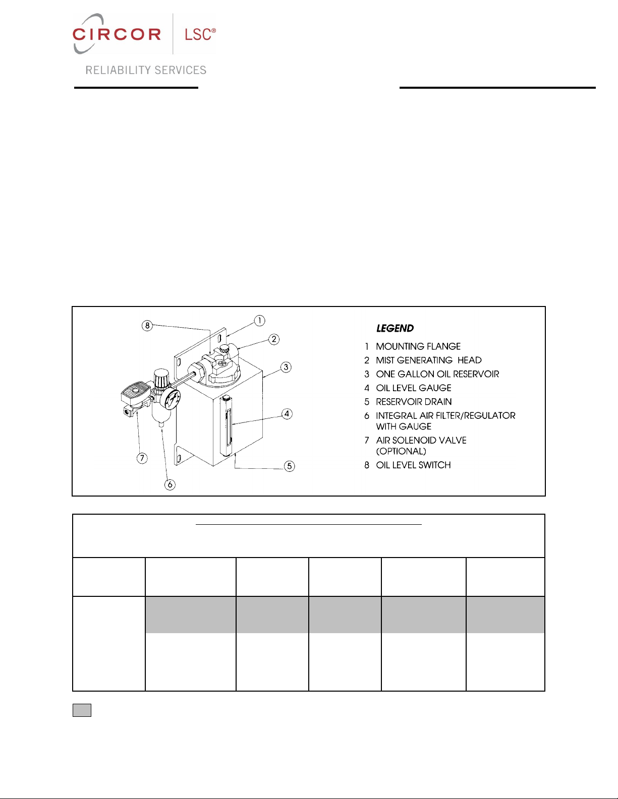
1. The Integral Air Filter/ Regulator is used to adjust the volume of air flow to the Vortexchamber which in turn controls oil mist volume,
refer to Item 7, Fig. No. 3. The volume of oil mist is proportioned to each bearing or application point by the reclassifier. With the air
by-pass valve (described below) closed, the air pressure regulator setting must be high enoughfor oilmistproduction (Min.10 PSIG).
Regulated air pressure should be adjusted to maintain proper mist pressure. Since changes in regulated air pressure affect the
volume of oil mist produced, it also affects oil consumption.
2. The OIL FLOW VALVE controls oil mist density (oil/air ratio). Its normal position is fullyclosed. By turning it counter clockwisetoward
"Less" (opening the by pass) the mist densitycan be reduced when leaner density oil mist is desired. It should not be opened more
than three turns. Adjustments to the oil flow valve do not affect oil mist pressure in the distribution lines or in the generator; see Fig. 6
for location.
Note: The oil/air ratio or mist density is also dependent on the characteristics of the oil, oil temperature, and supplyair temperature.
Density decreases with lower temperatures and higher oil viscosity.
3. The AIR BY-PASS VALVE controls mist pressure without increasing oil output, its normal position is fully closed, but by turning it
counter clockwise toward "Open" more air will be added to the oil mist leaving the generatorthus increasingmist pressure. Velocityof
mist through the distribution lines and reclassifiers will also increase when this valve is opened, see Fig. 6 for location.
Note: The oil/air ratio or mist density is reduced by opening the air by-pass valve. However, oil output is not affected.
Operation
The daily operation of the oil mist system has been reduced to checks of the generator and lubricatedequipment.Exceptforemergencies,
routine adjustment of the generator is not required. Each oil mist system, once installed and balanced, supplies a constant amount of oil
mist to a number of lubrication points. Any change in the oil mist pressure or in the regulated air pressure (load pressure) from the initial
set points is an indication that some component has failed. Minor adjustments that might offset the failure symptoms may lead to more
serious problems before detection and corrections can be made.
Daily Checks
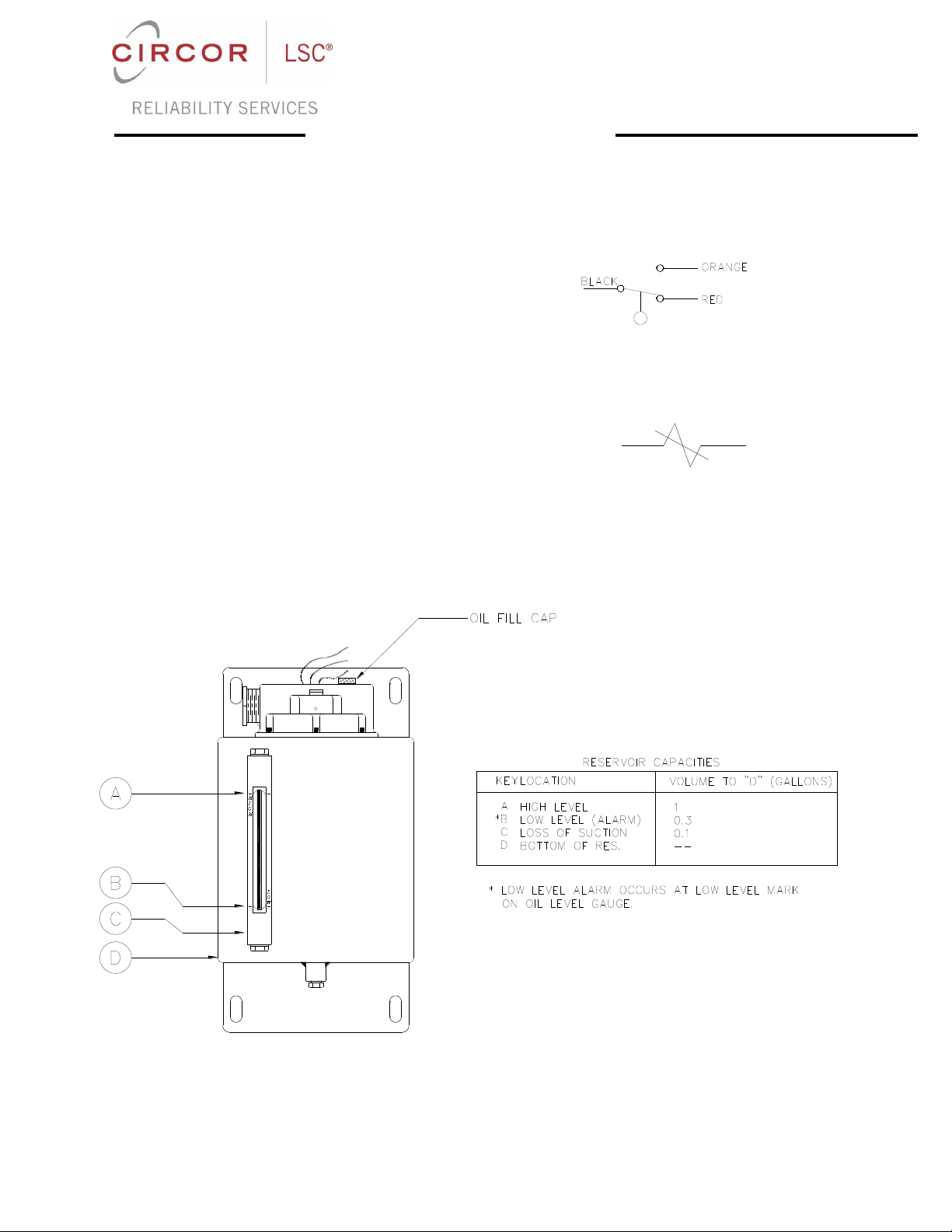
1. Check reservoir oil level and fill as required.
THE UNIT MUST BE SHUT DOWN TO FILL THROUGH THE OIL FILL CAP.
4. Check the regulated air pressure and mist header pressure gauges (if installed). Changes or fluctuations in mistpressure readings
indicate broken or plugged lines and fittings in the distribution system - correct as required.
Maintenance
The following maintenance procedures are recommended to help insure proper system operation.
1. Replace air filter element semi-annually.
2. Inspect and clean interior of reservoir semi-annually.
3. Inspect and clean oil suction tube screen semi-annually.
NOTE: When draining the reservoir the fill port must be open to atmosphere.
IMPORTANT: DO NOT DISASSEMBLE THE VORTEX MIST HEAD.

THE LEADER IN OIL MIST TECHNOLOGY
77740201 REV 4 January 17, 2019
FOR SALES, 24 HOUR SERVICE OR TECHNICAL INFORMATION:
15150 West Drive
Houston, TX 77053
713/464-6266 • FAX 713/464-9871 • 800-800-LUBE
DESIGN •MANUFACTURING •INSTALLATION •MAINTENANCE •TRAINING
This manual suits for next models
2
Table of contents