manuals.online logo
Brands
  1. Home
  2. •
  3. Brands
  4. •
  5. Cisco
  6. •
  7. Server
  8. •
  9. Cisco Content Delivery Engine CDE100 Manual

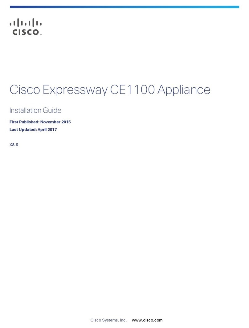
Cisco Content Delivery Engine CDE100 Manual

Americas Headquarters
Cisco Systems, Inc.
170 West Tasman Drive
San Jose, CA 95134-1706
USA
http://www.cisco.com
Tel: 408 526-4000
800 553-NETS (6387)
Fax: 408 527-0883
Cisco Content Delivery Engine
Hardware Installation Guide
August 2007
THE SPECIFICATIONS AND INFORMATION REGARDING THE PRODUCTS IN THIS MANUAL ARE SUBJECT TO
CHANGE WITHOUT NOTICE. ALL STATEMENTS, INFORMATION, AND RECOMMENDATIONS IN THIS
MANUAL ARE BELIEVED TO BE ACCURATE BUT ARE PRESENTED WITHOUT WARRANTY OF ANY KIND,
EXPRESS OR IMPLIED. USERS MUST TAKE FULL RESPONSIBILITY FOR THEIR APPLICATION OF ANY
PRODUCTS.
Text Part Number: OL-13478-01
THE SPECIFICATIONS AND INFORMATION REGARDING THE PRODUCTS IN THIS MANUAL ARE SUBJECT TO CHANGE WITHOUT NOTICE. ALL
STATEMENTS, INFORMATION, AND RECOMMENDATIONS IN THIS MANUAL ARE BELIEVED TO BE ACCURATE BUT ARE PRESENTED WITHOUT
WARRANTY OF ANY KIND, EXPRESS OR IMPLIED. USERS MUST TAKE FULL RESPONSIBILITY FOR THEIR APPLICATION OF ANY PRODUCTS.
THE SOFTWARE LICENSE AND LIMITED WARRANTY FOR THE ACCOMPANYING PRODUCT ARE SET FORTH IN THE INFORMATION PACKET THAT
SHIPPED WITH THE PRODUCT AND ARE INCORPORATED HEREIN BY THIS REFERENCE. IF YOU ARE UNABLE TO LOCATE THE SOFTWARE LICENSE
OR LIMITED WARRANTY, CONTACT YOUR CISCO REPRESENTATIVE FOR A COPY.
The following information is for FCC compliance of Class A devices: This equipment has been tested and found to comply with the limits for a Class A digital device, pursuant
to part 15 of the FCC rules. These limits are designed to provide reasonable protection against harmful interference when the equipment is operated in a commercial
environment. This equipment generates, uses, and can radiate radio-frequency energy and, if not installed and used in accordance with the instruction manual, may cause
harmful interference to radio communications. Operation of this equipment in a residential area is likely to cause harmful interference, in which case users will be required
to correct the interference at their own expense.
The following information is for FCC compliance of Class B devices: The equipment described in this manual generates and may radiate radio-frequency energy. If it is not
installed in accordance with Cisco’s installation instructions, it may cause interference with radio and television reception. This equipment has been tested and found to
comply with the limits for a Class B digital device in accordance with the specifications in part 15 of the FCC rules. These specifications are designed to provide reasonable
protection against such interference in a residential installation. However, there is no guarantee that interference will not occur in a particular installation.
Modifying the equipment without Cisco’s written authorization may result in the equipment no longer complying with FCC requirements for Class A or Class B digital
devices. In that event, your right to use the equipment may be limited by FCC regulations, and you may be required to correct any interference to radio or television
communications at your own expense.
You can determine whether your equipment is causing interference by turning it off. If the interference stops, it was probably caused by the Cisco equipment or one of its
peripheral devices. If the equipment causes interference to radio or television reception, try to correct the interference by using one or more of the following measures:
• Turn the television or radio antenna until the interference stops.
• Move the equipment to one side or the other of the television or radio.
• Move the equipment farther away from the television or radio.
• Plug the equipment into an outlet that is on a different circuit from the television or radio. (That is, make certain the equipment and the television or radio are on circuits
controlled by different circuit breakers or fuses.)
Modifications to this product not authorized by Cisco Systems, Inc. could void the FCC approval and negate your authority to operate the product.
The Cisco implementation of TCP header compression is an adaptation of a program developed by the University of California, Berkeley (UCB) as part of UCB’s public
domain version of the UNIX operating system. All rights reserved. Copyright © 1981, Regents of the University of California.
NOTWITHSTANDING ANY OTHER WARRANTY HEREIN, ALL DOCUMENT FILES AND SOFTWARE OF THESE SUPPLIERS ARE PROVIDED “AS IS” WITH
ALL FAULTS. CISCO AND THE ABOVE-NAMED SUPPLIERS DISCLAIM ALL WARRANTIES, EXPRESSED OR IMPLIED, INCLUDING, WITHOUT
LIMITATION, THOSE OF MERCHANTABILITY, FITNESS FOR A PARTICULAR PURPOSE AND NONINFRINGEMENT OR ARISING FROM A COURSE OF
DEALING, USAGE, OR TRADE PRACTICE.
IN NO EVENT SHALL CISCO OR ITS SUPPLIERS BE LIABLE FOR ANY INDIRECT, SPECIAL, CONSEQUENTIAL, OR INCIDENTAL DAMAGES, INCLUDING,
WITHOUT LIMITATION, LOST PROFITS OR LOSS OR DAMAGE TO DATA ARISING OUT OF THE USE OR INABILITY TO USE THIS MANUAL, EVEN IF CISCO
OR ITS SUPPLIERS HAVE BEEN ADVISED OF THE POSSIBILITY OF SUCH DAMAGES.
CCVP, the Cisco logo, and the Cisco Square Bridge logo are trademarks of Cisco Systems, Inc.; Changing the Way We Work, Live, Play, and Learn is a service mark of
Cisco Systems, Inc.; and Access Registrar, Aironet, BPX, Catalyst, CCDA, CCDP, CCIE, CCIP, CCNA, CCNP, CCSP, Cisco, the Cisco Certified Internetwork Expert logo,
Cisco IOS, Cisco Press, Cisco Systems, Cisco Systems Capital, the Cisco Systems logo, Cisco Unity, Enterprise/Solver, EtherChannel, EtherFast, EtherSwitch, Fast Step,
Follow Me Browsing, FormShare, GigaDrive, HomeLink, Internet Quotient, IOS, iPhone, IP/TV, iQ Expertise, the iQ logo, iQ Net Readiness Scorecard, iQuick Study,
LightStream, Linksys, MeetingPlace, MGX, Networking Academy, Network Registrar, Packet, PIX, ProConnect, ScriptShare, SMARTnet, StackWise, The Fastest Way to
Increase Your Internet Quotient, and TransPath are registered trademarks of Cisco Systems, Inc. and/or its affiliates in the United States and certain other countries.
All other trademarks mentioned in this document or Website are the property of their respective owners. The use of the word partner does not imply a partnership relationship
between Cisco and any other company. (0705R)
Any Internet Protocol (IP) addresses used in this document are not intended to be actual addresses. Any examples, command display output, and figures included in the
document are shown for illustrative purposes only. Any use of actual IP addresses in illustrative content is unintentional and coincidental.
Cisco Content Delivery EngineHardware Installation Guide
© 2007 Cisco Systems, Inc. All rights reserved.
iii
Cisco Content Delivery Engine Hardware Installation Guide
OL-13478-01
CONTENTS
Preface v
Document Revision History v
Document Organization v
Objectives vi
Audience vi
Related Documentation vi
Obtaining Documentation, Obtaining Support, and Security Guidelines vii
CHAPTER
1Overview of Content Delivery Engines 1-1
Hardware Features 1-2
Front Panel Control Buttons 1-2
LED Indicators 1-3
Input/Output Ports and Connectors 1-4
CHAPTER
2Installing the CDEs 2-1
Server Types 2-1
Safety Warnings 2-1
Tools and Parts Required 2-4
Installing the CDEs 2-4
Rack Installation Safety Guidelines 2-4
Preparing the CDEs for Rack Installation 2-4
Installing in the Rack 2-5
Making Physical Connections 2-6
Connecting Power Cords 2-6
Connecting Network Cables 2-8
Installing or Removing Disk Drives 2-8
CHAPTER
3Installing the Software and Initially Configuring a CDE 3-1
Before You Begin 3-1
Installation and Configuration Order 3-3
Running the BIOS Setup Utility 3-3
Running the BIOS Setup Utility for the CDE-100 3-3
Running the BIOS Setup Utility for the CDE-200 3-9
Contents
iv
Cisco Content Delivery Engine Hardware Installation Guide
OL-13478-01
Installing the Software 3-13
Initially Configuring a CDE 3-14
Assigning the Primary Interface 3-14
Running the Setup Utility 3-14
Verifying the CDSM 3-15
CHAPTER
4Hardware Troubleshooting 4-1
Troubleshooting Ethernet Adapters 4-1
Troubleshooting SATA Drives 4-2
APPENDIX
ATechnical Specifications A-1
CDE-100 A-1
CDE-200 A-2
Management A-2
APPENDIX
BConnector Pin Assignments B-1
CDE Server Connectors B-1
Serial Console Interface Connector Pin Assignments B-2
Serial Port Connector B-3
Ethernet Connector Pin Assignments B-3
Ethernet Port Connector B-4
Cable Pin Assignments B-5
I
NDEX
v
Cisco Content Delivery Engine Hardware Installation Guide
OL-13478-01
Preface
This preface describes the objectives and organization of this guide and contains the following sections:
•“Document Organization” section on page v
•“Objectives” section on page vi
•“Audience” section on page vi
•“Document Revision History” section on page v
•“Related Documentation” section on page vi
•“Obtaining Documentation, Obtaining Support, and Security Guidelines” section on page vii
Document Revision History
The Document Revision History table below records technical changes to this document.
Document Organization
Document Version Date Change Summary
OL-13478-01 August 20, 2007 This is the first version of this document.
Chapter Description
Chapter 1, “Overview of Content Delivery
Engines”
Provides a brief introduction to the Content
Delivery Engines (CDEs).
Chapter 2, “Installing the CDEs” Provides the necessary information to properly
install the CDS hardware components.
Chapter 3, “Installing the Software and Initially
Configuring a CDE”
Describes the initial installation of the CDS
release 2.0 software application suite onto the
CDEs, and the initial configuration of the CDE
using the Content Delivery System Manager
(CDSM).
Chapter 4, “Hardware Troubleshooting” Presents troubleshooting procedures for the CDS.
vi
Cisco Content Delivery Engine Hardware Installation Guide
OL-13478-01
Preface
Objectives
This guide documents the hardware features of the Cisco Internet Streamer (CDS) release 2.0, which
consists of the CDE-100 and CDE-200 when used only in Internet Streaming applications. It describes
the physical and performance characteristics of each CDE, explains how to install a CDE, and provides
troubleshooting information.
This guide does not describe system messages that you may receive and provides only initial
configuration procedures. For more information, see the “Related Documentation” section on page vi.
Audience
This guide is for the networking or computer technician responsible for installing the Cisco Internet
Streamer CDS release 2.0 hardware. You should be familiar with the concepts and terminology of
Ethernet and local area networking.
Related Documentation
These documents provide complete information about the CDS and are available from the Cisco.com
site:
•Release Notes for the Cisco Internet Streamer CDS 2.0
•Release Notes for Cisco CDA Visual Quality Experience Application, Release 2.0
•Cisco Internet Streamer CDS 2.0 Software Configuration Guide
•Cisco Content Delivery Engine 110 Hardware Installation Guide
•Cisco CDA Visual Quality Experience Application User Guide, Release 2.0 (
•Cisco Internet Streamer CDS 2.0 Documentation Roadmap
•Regulatory Compliance and Safety Information for the Cisco Internet Streamer CDS 2.0
•Regulatory Compliance and Safety Information for the Cisco Content Delivery Engine 110
•Cisco Internet Streamer CDS 2.0 Product Documentation
•Cisco Internet Streamer CDS 2.0 API Guide
You can access the software documents at the following URL:
http://www.cisco.com/en/US/products/ps7127/tsd_products_support_series_home.htmll
You can access the hardware documents at the following URL:
http://www.cisco.com/en/US/products/ps7126/tsd_products_support_series_home.html
Appendix A, “Technical Specifications” Describes the specifications of the CDS.
Appendix B, “Connector Pin Assignments” Lists the connector pin assignments for the CDEs.
Chapter Description
vii
Cisco Content Delivery Engine Hardware Installation Guide
OL-13478-01
Preface
Obtaining Documentation, Obtaining Support, and Security
Guidelines
For information on obtaining documentation, obtaining support, providing documentation feedback,
security guidelines, and also recommended aliases and general Cisco documents, see the monthly
What’s New in Cisco Product Documentation, which also lists all new and revised Cisco technical
documentation, at:
http://www.cisco.com/en/US/docs/general/whatsnew/whatsnew.html
viii
Cisco Content Delivery Engine Hardware Installation Guide
OL-13478-01
Preface
CHAPTER
1-1
Cisco Content Delivery Engine Hardware Installation Guide
OL-13478-01
1
Overview of Content Delivery Engines
This chapter provides an overview of the Content Delivery Engines (CDEs) and describes the hardware
features.
The Cisco Internet Streamer Content Delivery System (CDS) release 2.0 CDEs are the CDE-100 and
CDE-200 servers. Figure 1-1 shows the front view of the CDE-100 and Figure 1-2 shows the rear view
of the CDE-100.
Figure 1-1 CDE-100 Front View
Figure 1-2 CDE-100 Rear View
Figure 1-3 shows the front view of the CDE-200 and Figure 1-4 shows the rear view of the CDE-200.
Figure 1-3 CDE-200 Front View
211764
210823
211765
12
1-2
Cisco Content Delivery Engine Hardware Installation Guide
OL-13478-01
Chapter 1 Overview of Content Delivery Engines
Hardware Features
Figure 1-4 CDE-200 Rear View
Hardware Features
Each CDE-100 server is 1 rack unit (RU) high and contains one dual-core Intel Xeon processor with 4
GB of memory, four 150-GB Small Computer System Interface (SCSI) drives, and two Gigabit Ethernet
ports.
Each CDE-200 server is 2 RU high and contains two Intel Xeon processors with 8 GB of memory, twelve
500-GB Serial ATA (SATA) drives (10 used for content storage and 2 used in RAID-1 for system image
and management), and six Gigabit Ethernet ports.
Each CDE is designed to be rack-mounted in a standard 19-inch rack with a depth of 30 inches.
Front Panel Control Buttons
Figure 1-5 shows the CDE-100 front panel, and describes the front panel control buttons.
Figure 1-5 CDE-100 Front Panel Control Buttons
Figure 1-6 shows the CDE-200 front panel, and describes the front panel control buttons.
1Power Powers up the device. You may need to use a pen or the end of a straightened
paper clip to press the button.
2Reset Resets the device and runs the power-on self-test (POST). You may need to
use a pen or the end of a straightened paper clip to press the button.
Note This is a hardware reset button and does not restore the device to the
factory default software settings.
3CD eject Opens the CD drive tray.
211766
3
12
1-3
Cisco Content Delivery Engine Hardware Installation Guide
OL-13478-01
Chapter 1 Overview of Content Delivery Engines
Hardware Features
Figure 1-6 CDE-200 Front Panel Control Buttons
LED Indicators
Figure 1-7 shows the location of the CDE-100 front panel LEDs, and describes their functions.
Figure 1-7 CDE-100 Front Panel LEDs
1Power Powers up the device. You may need to use a pen or the end of a straightened
paper clip to press the button.
2Reset Resets the device and runs the power-on self-test (POST). You may need to
use a pen or the end of a straightened paper clip to press the button.
Note This is a hardware reset button and does not restore the device to the
factory default software settings.
211767
12
1 2
No. LED Color State Description
1Power Blue On Power is flowing to the device.
2Hard disk drive activity Blue On Associated hard disk drive is in use.
3Ethernet port 1 Blue On Port is connected.
4Ethernet port 2 Blue On Port is connected.
5CD-ROM drive activity Blue On CD-ROM drive is in use.
6Reset Blue On Reset is in progress.
211768
52 4 1
3 6
1-4
Cisco Content Delivery Engine Hardware Installation Guide
OL-13478-01
Chapter 1 Overview of Content Delivery Engines
Hardware Features
Figure 1-8 shows the location of the CDE-200 front panel LEDs, and describes their function.
Figure 1-8 CDE-200 Front Panel LEDs
Input/Output Ports and Connectors
The CDEs support the following I/O connectors on the rear of the device:
•Ethernet connectors
•Serial connector
•Video and audio connectors (on optional adapter)
Figure 1-9 shows the location of the CDE-100 back panel ports and connectors.
No. LED Color State Description
1Power Blue On Device is powering on.
2Hard disk drive activity Blue On Associated hard disk drive is in use.
3Ethernet port 1 Blue On Port is connected.
4Ethernet port 2 Blue On Port is connected.
211769
12
12
3 4
1 2
1-5
Cisco Content Delivery Engine Hardware Installation Guide
OL-13478-01
Chapter 1 Overview of Content Delivery Engines
Hardware Features
Figure 1-9 CDE-100 Connector Locations
Figure 1-10 shows the location of the CDE-200 back panel connectors and receptacles.
Figure 1-10 CDE-200 Connector Locations
Note The system software does not support the use of a keyboard or mouse (Personal System 2 [PS/2] or
Universal Serial Bus [USB]). However, the keyboard and mouse are supported by the BIOS for POST,
and the BIOS Setup Utility as described in Chapter 3, “Installing the Software and Initially Configuring
a CDE.”
1Power connector 5VGA interface
2Mouse connector 6GigabitEthernet 1/0
3Keyboard connector 7GigabitEthernet 2/0
4Serial console interface
211770
4 5 6 7
1 2
3
1Power connectors 5VGA interface
2Mouse connector 6GigabitEthernet 1/0
3Keyboard connector 7GigabitEthernet 2/0
4Serial console interface 8Stream interfaces (G3/0, G4/0, G5/0, G6/0)
1-6
Cisco Content Delivery Engine Hardware Installation Guide
OL-13478-01
Chapter 1 Overview of Content Delivery Engines
Hardware Features
Caution In some CDE-200 chassis the streaming interface NICs are installed in slots 4 and 5 (counting from the
left-most slot). In this hardware configuration, the Gigabit Ethernet interfaces on the motherboard are
detected as interfaces 3/0 and 4/0, and the interfaces on the NICs are detected as 1/0, 2/0, 5/0, and 6/0.
The interface numbering must be taken into consideration when configuring IP addresses and
port-channels.
CHAPTER
2-1
Cisco Content Delivery Engine Hardware Installation Guide
OL-13478-01
2
Installing the CDEs
This chapter provides the necessary information to properly install the CDEs. This chapter contains the
following sections:
•Server Types, page 2-1
•Safety Warnings, page 2-1
•Tools and Parts Required, page 2-4
•Installing the CDEs, page 2-4
Server Types
The Content Delivery System (CDS) consists of servers that are connected through Ethernet switches.
The Intel Xeon-based servers are populated with multiple high-capacity hard drives.
There are three distinct server types in the Content Delivery System:
•System Manager (CDSM)—CDE-100 or CDE-200
•Service Engine (SE)—CDE-200
•Service Router (SR)—CDE-200
Depending on your application, you may have multiple SEs and SRs. A network switch is employed to
link multiple servers together within a larger network.
Safety Warnings
These warnings are translated into several languages in the Regulatory Compliance and Safety
Information for the Cisco Internet Streamer CDS 2.0 document that ships with the servers.
Warning
Read the installation instructions before you connect the system to its power source.
Statement 10
Warning
The device is designed to work with TN power systems.
Statement 19
2-2
Cisco Content Delivery Engine Hardware Installation Guide
OL-13478-01
Chapter 2 Installing the CDEs
Safety Warnings
Warning
The ports labeled “Ethernet,” “10BaseT,” “Token Ring,” “Console,” and “AUX” are safety
extra-low voltage (SELV) circuits. SELV circuits should only be connected to other SELV
circuits. Because the BRI circuits are treated like telephone-network voltage, avoid
connecting the SELV circuit to the telephone network voltage (TNV) circuits.
Statement 22
Warning
Connect the device to a grounded power outlet.
Statement 25
Warning
There is the danger of explosion if the battery is replaced incorrectly. Replace the battery
only with the same or equivalent type recommended by the manufacturer. Dispose of used
batteries according to the manufacturer’s instructions.
Statement 33
Warning
This unit is intended for installation in restricted access areas. A restricted access area is
where access can only be gained by service personnel through the use of a special tool,
lock and key, or other means of security, and is controlled by the authority responsible for
the location.
Statement 37
Warning
Before working on equipment that is connected to power lines, remove jewelry (including
rings, necklaces, and watches). Metal objects will heat up when connected to power and
ground and can cause serious burns or weld the metal object to the terminals.
Statement 43
Warning
Only trained and qualified personnel should be allowed to install or replace this equipment.
Statement 49
Warning
During this procedure, wear grounding wrist straps to avoid ESD damage to the card. Do not
directly touch the backplane with your hand or any metal tool, or you could shock yourself.
Statement 94
Warning
Because invisible radiation may be emitted from the aperture of the port when no fiber
cable is connected, avoid exposure to radiation and do not stare into open apertures.
Statement 125
Warning
This equipment must be installed and maintained by service personnel as defined by
AS/NZS 3260. Incorrectly connecting this equipment to a general purpose outlet could be
hazardous. The telecommunications lines must be disconnected 1) before unplugging the
main power connector and/or 2) while the housing is open.
Statement 185
2-3
Cisco Content Delivery Engine Hardware Installation Guide
OL-13478-01
Chapter 2 Installing the CDEs
Safety Warnings
Warning
For Nordic countries (Norway, Finland, Sweden and Denmark) this system must be installed
in a Restricted Access Location, where the voltage of the main ground connection of all
equipment is the same (equipotential earth) and the system is connected to a grounded
electrical outlet.
Statement 328
Warning
Do not work on the system or connect or disconnect cables during periods of lightning
activity.
Statement 1001
Warning
Class 1 laser product.
Statement 1008
Warning
This equipment must be grounded. Never defeat the ground conductor or operate the
equipment in the absence of a suitably installed ground conductor. Contact the appropriate
electrical inspection authority or an electrician if you are uncertain that suitable grounding
is available.
Statement 1024
Warning
Class 1 LED product.
Statement 1027
Warning
This unit might have more than one power supply connection. All connections must be
removed to de-energize the unit.
Statement 1028
Warning
Ultimate disposal of this product should be handled according to all national laws and
regulations.
Statement 1040
Warning
This product requires short-circuit (overcurrent) protection, to be provided as part of the
building installation. Install only in accordance with national and local wiring regulations.
Statement 1045
Warning
This warning symbol means danger. You are in a situation that could cause bodily injury.
Before you work on any equipment, be aware of the hazards involved with electrical
circuitry and be familiar with standard practices for preventing accidents. Use the
statement number provided at the end of each warning to locate its translation in the
translated safety warnings that accompanied this device.
Statement 1071
Warning
This product is not intended to be directly connected to the Cable Distribution System.
Additional regulatory compliance and legal requirements may apply for direct connection
to the Cable Distribution System. This product may connect to the Cable Distribution System
ONLY through a device that is approved for direct connection.
Statement 1078
2-4
Cisco Content Delivery Engine Hardware Installation Guide
OL-13478-01
Chapter 2 Installing the CDEs
Tools and Parts Required
You need the following tools to install the CDE components:
•CDE-100 or CDE-200
•Antistatic mat
•Properly grounded ESD-preventive device
•1/4-inch flat-blade screwdriver
•3/16-inch flat-blade screwdriver
•Number 2 Phillips screwdriver
Installing the CDEs
Installing the CDS hardware consists of the following tasks:
•Rack Installation Safety Guidelines, page 2-4
•Preparing the CDEs for Rack Installation, page 2-4
•Installing in the Rack, page 2-5
•Making Physical Connections, page 2-6
•Installing or Removing Disk Drives, page 2-8
Rack Installation Safety Guidelines
Before installing your device in a rack, review the following guidelines:
•Two or more people are required to install the device in a rack.
•Ensure that the room air temperature is below 95°F (35°C).
•Do not block any air vents; usually 6 inches (15 cm) of space provides proper airflow.
•Plan the device installation starting from the bottom of the rack.
•Install the heaviest device in the bottom of the rack.
•Do not extend more than one device out of the rack at the same time.
•Remove the rack doors and side panels to provide easier access during installation.
•Connect the device to a properly grounded outlet.
•Do not overload the power outlet when installing multiple devices in the rack.
•Do not place any object weighing more than 110 lb (50 kg) on top of rack-mounted devices.
Preparing the CDEs for Rack Installation
Before installing a CDE-100 in the rack, ensure the following hardware configuration is set:
•All dip switches are set in the OFF (down) position.
•CD-ROM drive is connected to the primary IDE cable.
2-5
Cisco Content Delivery Engine Hardware Installation Guide
OL-13478-01
Chapter 2 Installing the CDEs
Installing the CDEs
•CompactFlash drive is connected to the secondary IDE cable.
Before installing a CDE-200 in the rack, ensure the following hardware configuration is set:
•Onboard SCSI controller is disabled
•80 GB hard drive is connected to the primary IDE cable.
•CompactFlash drive is connected to the secondary IDE cable.
To verify correct hardware configuration, perform the following steps:
Step 1 Use proper electro-static discharge (ESD) procedures when working on internal components.
Step 2 Remove the cover on the chassis.
Step 3 Make sure the following configuration is set for the applicable chassis:
CDE-100
•Make sure the dip switch at the back of the disk array case is set in the OFF (down) position.
•Make sure the CD-ROM is connected to the primary IDE cable, and the CompactFlash drive is
connected to the secondary IDE cable. There are two IDE connectors on the motherboard. The one
parallel to the front panel of the chassis is the primary IDE connector. The one in the upright position
is the secondary IDE connector. If necessary, swap the internal CD-ROM drive with the
CompactFlash drive in order to ensure the CompactFlash drive is connected to the secondary IDE
cable.
CDE-200
•Make sure the 80 GB hard drive is connected to the primary IDE cable, and the CompactFlash drive
is connected to the secondary IDE cable. If necessary, swap the internal CD-ROM drive with the
CompactFlash drive in order to ensure the CompactFlash drive is connected to the secondary IDE
cable.
•It is very important that the onboard SCSI controller be disabled. Do this by verifying that the
jumper labeled “JPA-1” (located about two inches below the center PCI-X slot—slot 3 of 5) has pins
2 and 3 connected (instead of 1 and 2). Pin 1 is closest to the rear of the case and pin 3 is closest to
the front.
Step 4 Replace the cover on the chassis.
Installing in the Rack
The CDEs are best rail-mounted in a standard 19-inch wide by 30-inch deep rack.
To install the servers in a rack, perform the following steps:
Step 1 Mount the rails to the CDE.
Step 2 Mount the CDE rails to the rack.
At least two people are required to lift the unit and place it at the desired position in the rack; holding it
steady. A third person secures the unit into the rack.
2-6
Cisco Content Delivery Engine Hardware Installation Guide
OL-13478-01
Chapter 2 Installing the CDEs
Installing the CDEs
Caution Be sure that the chassis is securely attached to both sides of the rack to avoid the possibility
of chassis flexing.
When installing the CDEs, consider the following:
•Elevated operating ambient temperature—In a closed or multi-unit rack assembly, this is the
operating ambient temperature of the rack. Environment temperature may be greater than the room
ambient temperature. Do not exceed the manufacturer’s recommended ambient temperature.
•Reduced airflow—Installation of the equipment in a rack should be such that the amount of airflow
for safe operation of the equipment is not compromised.
•Mechanical loading—Mounting of the equipment in the rack should be such that a hazardous
condition is not achieved because of uneven mechanical loading.
Making Physical Connections
After mounting the servers, continue the hardware setup by making the physical connections for power
and network.
Caution The unit is intended for indoor use. It is provided with numerous standard USB and Ethernet ports. This
product is not intended to be directly connected to the Telecommunication Network System. Additional
regulatory compliance and legal requirements may apply for direct connection to the Telecommunication
Network System. This product may connect to the Telecommunication Network System only through a
device that is approved for direct connection.
Connecting Power Cords
Redundant power connectors are located at the rear of the chassis as shown in Figure 2-1 and Figure 2-2.
Power connections have the following properties:
•Chassis power inlets accept AC (120 V or 220 V) or –48 VDC.
•Power modules are hot swappable.
•The CDE-100 chassis contains one VAC or VDC power port; the CDE-200 chassis contains two
VAC or VDC power ports.

This manual suits for next models

1

Other Cisco Server manuals

Cisco CiscoWorks WLSE 1130-19 Operator's manual

Cisco

Cisco CiscoWorks WLSE 1130-19 Operator's manual

Cisco UCS C420 Installation and maintenance instructions

Cisco

Cisco UCS C420 Installation and maintenance instructions

Cisco UCS C24 M3 User manual

Cisco

Cisco UCS C24 M3 User manual

Cisco NAC-3300 Series User manual

Cisco

Cisco NAC-3300 Series User manual

Cisco PDS2000 User manual

Cisco

Cisco PDS2000 User manual

Cisco C880 M4 User manual

Cisco

Cisco C880 M4 User manual

Cisco AS5300-96VOIP-A User manual

Cisco

Cisco AS5300-96VOIP-A User manual

Cisco UCS C240 M5 Installation and maintenance instructions

Cisco

Cisco UCS C240 M5 Installation and maintenance instructions

Cisco UCS 5100 Quick start guide

Cisco

Cisco UCS 5100 Quick start guide

Cisco Firepower 1120 User manual

Cisco

Cisco Firepower 1120 User manual

Cisco CPS-UCS-2RU-K9 User manual

Cisco

Cisco CPS-UCS-2RU-K9 User manual

Cisco TelePresence Server 7010 User manual

Cisco

Cisco TelePresence Server 7010 User manual

Cisco UCS B440 M2 User manual

Cisco

Cisco UCS B440 M2 User manual

Cisco UCS C200 M2 System manual

Cisco

Cisco UCS C200 M2 System manual

Cisco UCS C240 M3 User manual

Cisco

Cisco UCS C240 M3 User manual

Cisco UCS C22 Installation and maintenance instructions

Cisco

Cisco UCS C22 Installation and maintenance instructions

Cisco C880 M4 User manual

Cisco

Cisco C880 M4 User manual

Cisco VCS Series User manual

Cisco

Cisco VCS Series User manual

Cisco SNS-3415 series Instruction Manual

Cisco

Cisco SNS-3415 series Instruction Manual

Cisco APIC M3 Installation and maintenance instructions

Cisco

Cisco APIC M3 Installation and maintenance instructions

Cisco UCS B440 M2 System manual

Cisco

Cisco UCS B440 M2 System manual

Cisco UCS C22 M3 System manual

Cisco

Cisco UCS C22 M3 System manual

Cisco TelePresence Server 7010 Reference guide

Cisco

Cisco TelePresence Server 7010 Reference guide

Cisco expressway ce1100 User manual

Cisco

Cisco expressway ce1100 User manual

Popular Server manuals by other brands

Wyse TM 9000 Series reference guide

Wyse

Wyse TM 9000 Series reference guide

Lenovo ThinkServer RD240 Software user's guide

Lenovo

Lenovo ThinkServer RD240 Software user's guide

HPE ProLiant m710x User and maintenance guide

HPE

HPE ProLiant m710x User and maintenance guide

Bull ESCALA PL 240 Series manual

Bull

Bull ESCALA PL 240 Series manual

Dell PowerEdge M620 Getting started guide

Dell

Dell PowerEdge M620 Getting started guide

IBM 8840 - eServer xSeries 346 user guide

IBM

IBM 8840 - eServer xSeries 346 user guide

Gigabyte W291-Z00 installation instructions

Gigabyte

Gigabyte W291-Z00 installation instructions

SMART Embedded Computing SE1700 manual

SMART Embedded Computing

SMART Embedded Computing SE1700 manual

Supermicro SuperServer 5019C-M4L user manual

Supermicro

Supermicro SuperServer 5019C-M4L user manual

Lenovo ThinkSystem SR655 V3 user guide

Lenovo

Lenovo ThinkSystem SR655 V3 user guide

LG Cloud T Series CBT42 owner's manual

LG

LG Cloud T Series CBT42 owner's manual

Alcatel-Lucent Extended Communication Server Installation & configuration manual

Alcatel-Lucent

Alcatel-Lucent Extended Communication Server Installation & configuration manual

QUANTA STRATOS S810 Series user guide

QUANTA

QUANTA STRATOS S810 Series user guide

Supermicro SuperServer SYS-221BT-HNTR user manual

Supermicro

Supermicro SuperServer SYS-221BT-HNTR user manual

Dell PowerEdge C410X Hardware owner's manual

Dell

Dell PowerEdge C410X Hardware owner's manual

AIC SB401-LB user manual

AIC

AIC SB401-LB user manual

Intel A2400SATAKIT2 installation guide

Intel

Intel A2400SATAKIT2 installation guide

Post Genie WMS-2208R user manual

Post Genie

Post Genie WMS-2208R user manual

manuals.online logo
manuals.online logoBrands
  • About & Mission
  • Contact us
  • Privacy Policy
  • Terms and Conditions

Copyright 2025 Manuals.Online. All Rights Reserved.