manuals.online logo
Brands
  1. Home
  2. •
  3. Brands
  4. •
  5. Cisco
  6. •
  7. Switch
  8. •
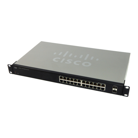
  9. Cisco Catalyst X6524 Quick reference guide

Cisco Catalyst X6524 Quick reference guide

All contents are Copyright © 1992–2005 Cisco Systems, Inc. All rights reserved. Important Notices and Privacy Statement.
Page 1 of 1
White Paper
Quality of Service on Cisco Catalyst 6500
INTRODUCTION
Picture a busy bank branch. The queue of customers lining up to see the tellers is very long. When you arrive at the bank branch, you are
immediately recognized as one of the bank’s valued customers. You are escorted to a separate queue for “special” customers away from the hustle
and bustle of the long queue. In this special queue you get served by the teller immediately. As a special customer, you have just been given
a preferential level of service that exceeds what the average customer receives.
Like in the bank example above, quality of service (QoS) in Cisco®Catalyst®6500 Family line cards is a tool that is used to provide preferential
service for select traffic as it transits the switch. Over time and with the advancements in hardware and software technology, a number of QoS tools
have now become available. QoS in itself is not one feature, but a collection of features that when combined provide a powerful way to identify
different classes of traffic, prioritize them, and then service that traffic ahead of other lower priority traffic entering and leaving the switch.
This document will attempt to provide a high level overview of the QoS features found on the Cisco Catalyst 6500. It will explain what the features
are, how they work, and where in hardware they are performed.
WHERE IS QoS PERFORMED?
The Cisco Catalyst 6500 performs QoS on the supervisor and the line card. The supervisor contains a daughter card called the policy feature card
(PFC). Although the PFC is primarily responsible for the hardware forwarding of packets, it also performs a number of important QoS tasks. Since
the Cisco Catalyst 6500 was introduced in 1999, a number of PFC models aligned with specific supervisor models have been introduced. Typically
the introduction of a new PFC coincides with the arrival of new QoS features. This is especially true of the PFC3, which when introduced with the
Cisco Catalyst 6500 Series Supervisor Engine 720 in 2003 added a number of new QoS features not found in earlier PFC models.
The Cisco Catalyst 6500 line card is the other component that performs QoS, and those QoS features are primarily influenced by the port
application-specific integrated circuit (ASIC). The level of QoS support on the line card is dependent on the functionality built into the line-card port
ASIC. For this reason, the QoS capabilities can differ between different generations of the Cisco Catalyst 6500 Family.
Toward the end of this paper, a set of tables give an overview of the QoS features available on each of the line cards and PFC versions.
A QUICK RECAP ON SETTING PRIORITY
When data is sent through a network, it can be tagged with a priority value. When the data passes through a network device, the priority value is
used by that network device to determine how it should treat the packet. Data can be tagged with a priority value as described in the following
sections.
Class of Service
When a packet is transmitted out an Ethernet port, it has an Ethernet header attached to it. This Ethernet header can include an optional VLAN tag
(also referred to as an IEEE 802.1Q VLAN tag). Within the VLAN tag is a 3-bit field called the class-of-service (CoS) field. These 3 bits can be
manipulated to yield eight different priority values. Figure 1 shows where in the Ethernet header the priority bits are found.
© 2005 Cisco Systems, Inc. All rights reserved.
Important notices, privacy statements, and trademarks of Cisco Systems, Inc. can be found on cisco.com.
Page 2 of 18
Figure 1. CoS Field
Cisco Systems®supports the Inter-Switch Link (ISL) VLAN tagging option on selected Cisco Catalyst 6500 line cards. ISL is a Cisco proprietary
VLAN tagging option that also supports an inbuilt 3-bit CoS field just like the IEEE 802.1Q option mentioned earlier.
Type of Service
Built into every IP packet is an IP header, and like in the Ethernet example earlier, the IP header also contains a field that defines a priority value
for this packet. This field is the type-of-service (ToS) field. Unlike the CoS field, the ToS field is an 8-bit field. There are two ways to set a priority
value in the ToS field. One method, called IP precedence, uses the 3 most significant bits of the ToS field to yield eight priority values.
Differentiated Services Code Point (DSCP) is a second method for assigning a priority to an IP packet. DSCP uses the 6 most significant bits of the
ToS field to yield 64 different priority values. Figure 2 shows where the ToS bits are found in the IP header.
Figure 2. Reading IP Precedence and DSCP from the ToS Byte
© 2005 Cisco Systems, Inc. All rights reserved.
Important notices, privacy statements, and trademarks of Cisco Systems, Inc. can be found on cisco.com.
Page 3 of 18
CATEGORIES OF QoS FEATURES
Explaining what QoS features are available on the Cisco Catalyst 6500 is best served by categorizing them into one of the following major groups.
These groups are:
•Classification
•Queuing
•Congestion avoidance
•Policing
•Rewrite
•Scheduling
The use of classification provides a way for the switch to identify specific traffic so that it can determine what level of service needs to be applied to
that data. Identification can be achieved by a number of means, such as inspecting primary fields in the packet header or looking at the port of
arrival. The main set of classification tools provided by the Cisco Catalyst 6500 are the access control list (ACL) and per-port trust setting.
Queuing (also known as congestion management) provides a way to temporarily store data when the arrival rate of data is larger than what can be
sent. Like in the earlier bank example, the switch port will use a queue to place data into a temporary holding area until the data can be processed
and forwarded. Memory is allocated to each queue, which provides the buffer space for data awaiting service. The number of queues and the amount
of buffering available are hardware dependent and are determined by the line card in use. A table later in this document provides the queue type and
per-port memory with different line-card options.
Managing the queues and buffers is the primary goal of congestion avoidance. As a queue starts to fill up with transient data, it is important to try
to ensure that the available memory in the queue does not fill up completely. If this happens, subsequent packets coming into the port will simply be
dropped, irrespective of the priority that they could have received. This could have a detrimental effect on the performance of critical applications.
For this reason, congestion avoidance techniques are used to reduce the risk of a queue from filling up completely. Queue thresholds are used to
trigger when certain levels of occupancy are met. After a threshold has been crossed, the system can start to randomly drop lower priority data while
trying to keep as much of the higher priority data resident in the queue. Examples of congestion avoidance technologies include Weighted Random
Early Detection (WRED), tail drop, and maps.
The act of policing in the switch provides a means to limit the amount of bandwidth that traffic traveling through a given port or collection of ports
in a VLAN can use. Policing works by defining an amount of data that the switch is willing to send or receive in Kbps. The policing policy uses
an ACL to identify the traffic to which the policer will be applied.
Multiple policing policies can be active in the switch at any one time, allowing an administrator to set different rates for different classes of traffic.
Policing can be set up so that it rate limits all traffic entering a given port or VLAN to a given rate or by limiting each new flow to a given rate.
Rewrite is the action of changing the priority setting of the packet. Each packet consists of the data and a header. The header among other things
contains information such as where the data has come from (that is, the sending device’s source address) and where the data is destined (that is,
the target device’s destination address). Built into the header is the priority value that can be used to indicate to switches and routers in the network
path of the priority of that piece of data. The Cisco Catalyst 6500 has the ability to change that priority value (increase or decrease it) if required
based on any policies that may be set by the network administrator.
Scheduling is the QoS mechanism used to empty the queues of data and send the data onward to its destination. A number of scheduling options are
available in the Cisco Catalyst 6500—for example, Weighted Round Robin (WRR), Deficit Weighted Round Robin (DWRR), Shaped Round Robin
(SRR), and strict priority queuing.
© 2005 Cisco Systems, Inc. All rights reserved.
Important notices, privacy statements, and trademarks of Cisco Systems, Inc. can be found on cisco.com.
Page 4 of 18
Now that the major QoS groups have been explained, it is pertinent to point out where in the QoS processing path these actions take place. Figure 3
provides a high-level overview of where those actions occur.
Figure 3. Cisco Catalyst 6500 QoS Processing Model
The following section will attempt to provide some insight into the many QoS features that make up the QoS feature toolkit now available
on the Cisco Catalyst 6500.
THE QoS FEATURE TOOLKIT
The Cisco Catalyst 6500 is primed with a number of QoS features that when combined provide an effective vehicle to better service higher priority
traffic. The following section will attempt to present a high-level overview of the major QoS features in the Cisco Catalyst 6500.
Modular QoS Command-Line Interface
When a Cisco Catalyst 6500 runs native Cisco IOS®Software, some (not all) of the QoS configuration on the switch follows the modular QoS
command-line interface (MQC) structure that is also found in Cisco IOS Software running on Cisco routers. The normal rules of configuration
are such that a class map is built incorporating the ACLs that identify the traffic that will have QoS applied to them. The class map is then referenced
within a policy map, which contains the QoS policy that will be applied to the switch port (or VLAN). The policy is then applied to the physical or
logical interface. A high-level view of this process is shown in Figure 4.
Figure 4. MQC
© 2005 Cisco Systems, Inc. All rights reserved.
Important notices, privacy statements, and trademarks of Cisco Systems, Inc. can be found on cisco.com.
Page 5 of 18
A primary differentiator between MQC on the Cisco Catalyst 6500 and router Cisco IOS Software is in the application of specific QoS features.
The Cisco Catalyst 6500 implements much of its QoS functionality in hardware. Router Cisco IOS Software differs in that it primarily implements
most features in software. For this reason, there are differences in how certain features are configured. More importantly, there are some QoS
features that are found in router Cisco IOS Software that are not found in the Cisco Catalyst 6500 hardware.
Ingress QoS: Trust
A packet can arrive at an interface with a priority value already present in the packets header. A question then arises for the switch: Is this priority
setting valid? Was it set by a valid application or network device according to predefined rules? Or maybe this priority setting was set by a user
hoping to get better service from the network? Either way, the switch has to make that determination and decide whether to honor the priority
valueµ or change it to another value. How the switch makes this determination is by using the port “trust” setting. (See Figure 5.)
Figure 5. Switch Port Trust Settings
When QoS is enabled on a switch, by default, all ports are placed into a state of untrusted. In this mode, any packet with an existing priority setting
that is received on an untrusted port will have its priority setting reset to a default CoS value (the default CoS value is zero). It is the responsibility
of the network administrator to identify ports where the priority value should be honored. For instance, connections to selected servers, IP
telephones, and IP call managers are examples of ports that should be set to trust the incoming priority setting.
When setting trust, the switch port can be set to trust one of the three priority settings, CoS, IP precedence, or DSCP. If a port is going to be set to
trust the incoming priority value, the network administrator has to make the determination of which of the three priority settings will be trusted.
Ingress and Egress QoS: Switch Port Queues
All line cards in the Cisco Catalyst 6500 provide a fixed set of ingress (also known as input or receive) queues and egress (also known as output or
transmit) queues per port. The number of queues is fixed in hardware on the line card and cannot be changed. Associated with the queue is
an amount of buffer memory that the queue uses to temporarily hold transient data. On some line cards, there is a dedicated amount of memory
available to each port. On other line cards, a pool of memory is shared between a set group of ports. A table later in this paper provides a summary
list of line cards, the queue structures on each, and the amount of buffering available to each port on the line card.
On select line cards, a strict priority queue is made available. This special queue can be used for latency-sensitive traffic and is designed to forward
data immediately when a packet arrives in that queue. More information on the strict priority queue is detailed later in this paper.
Ingress and Egress QoS: Thresholds
Thresholds have multiple uses within a queue. They are used within a queue to identify when the memory buffers have reached a certain predefined
utilization. After the threshold has been exceeded, the switch port will initiate a process to start dropping packets from the queue. One of two
mechanisms—tail drop and WRED—is typically used to perform this duty. Both of these processes are described later in this paper.
© 2005 Cisco Systems, Inc. All rights reserved.
Important notices, privacy statements, and trademarks of Cisco Systems, Inc. can be found on cisco.com.
Page 6 of 18
The threshold is also used to associate itself with certain packets tagged with a priority value. When the threshold has been exceeded, the WRED
process will attempt to drop packets associated with that breached threshold level. The network administrator also has the ability to set the threshold
level.
Ingress and Egress QoS: Maps
The Cisco Catalyst 6500 uses maps in a number of forms to perform different duties. The following section summarizes the different maps available.
Maps: Mapping a Packet to a Queue or Threshold
Given that a switch port can have multiple queues, a way must be provided for the switch to determine in which queue a given piece of data should
be placed. The way in which this is determined is by using a map. A map sets out a two-column table. The first column contains the priority value
that would be found in the packet’s header. The second column contains the queue (and threshold in that queue) to which the packet should be
assigned. This is shown in Figure 6.
Figure 6. Mapping a Packet to a Queue or Threshold
Maps: Mapping Priority Values
When a packet arrives at a switch port, it can be primed with a priority value. The trust setting of the port will determine which priority setting (ToS
or CoS) will be honored by the switch. As the packet passes through the switch (that is, after it has arrived on the input port and prior to it being sent
out the output port), it is assigned a priority value that is only used internal to the switch. This internal priority value is referred to as the internal
DSCP. A map is used to derive the internal DSCP from the incoming packet’s priority setting. After the packet has passed through the switch,
another map is used to derive what the CoS value will be written as for the packet when it is transmitted out the switch port. A summary of these
maps is presented in Table 1.
Table 1. Map Summary
Map Name Related Trust Setting Used on Input or Output Map Description
CoS to DSCP Map Trust CoS Input Derives the internal DSCP from the incoming CoS value
IP Precedence to DSCP Map Trust IP precedence Input Derives the internal DSCP from the incoming IP
precedence value
DSCP to CoS Map – Output Derives the CoS for the outbound packet from the internal
DSCP
© 2005 Cisco Systems, Inc. All rights reserved.
Important notices, privacy statements, and trademarks of Cisco Systems, Inc. can be found on cisco.com.
Page 7 of 18
Figure 7 shows two of the maps (on ingress) that can be used to derive the internal DSCO priority value.
Figure 7. Mapping Priority to Internal DSCP
Maps: Policing Map
Although policing is primarily designed to limit traffic to a set amount of bandwidth, it also has the ability to reduce the priority value of any data
that exceeds the set rate. When this option is configured, the policer uses a map to identify what priority it will mark the data down to.
The map used to perform this task is called the policed-dscp-map. It is a table that contains two columns: the left column is the original priority
value, and the matching value in the column on the right is what value the packet will be marked down to.
Maps: Egress DSCP Mutation
When a packet arrives at a switch port, the trust setting of that port will derive an internal priority value (known as internal DSCP, as described
earlier) that it uses to assign service to the packet while it transits the switch. When the packet is transmitted out a switch port, the actual DSCP
value (written into the IP header) in the outgoing packet is derived from the internal DSCP value. (See Figure 8.)
© 2005 Cisco Systems, Inc. All rights reserved.
Important notices, privacy statements, and trademarks of Cisco Systems, Inc. can be found on cisco.com.
Page 8 of 18
Figure 8. Egress DSCP Mutation
Egress DSCP mutation provides a way to change the DSCP value in the outgoing packet. An egress DSCP map table is used to tell the switch what
DSCP value to write in the outbound packet based on the packet’s internal DSCP value. Egress DSCP mutation relies on the presence of a PFC3A,
PFC3B, or PFC3BXL to support this feature.
Maps: Ingress CoS Mutation
Support for this feature is present on some of the newer Cisco Catalyst 6500 line cards. Specifically, it is supported on the CEF720 series 48 port
GETX and SFP line card, the CEF720 series 4 port 10GE line card and the CEF720 series 24 port SFP line card. Each of these line cards in turn
requires the presence of a Supervisor Engine 720 to work in the chassis.
When a port on one of these line cards is configured as an IEEE 802.1Q trunk port, ingress CoS mutation can be configured. What this feature
allows the user to do is to change the incoming CoS value to another CoS value. A map is provided that lists what the incoming CoS value will be
changed to. The administrator can change the map table to suit local policy requirements.
Ingress and Egress QoS: Policing
The PFC on the supervisor engine implements policing in a number of forms. The following sections provide an insight into the different policing
actions available on the PFC.
Policing: Aggregate Policing
An aggregate policer is a term used to define a rate-limiting policy that applies to all traffic on a given port or VLAN that matches a set of
classification criteria. This type of policer can be applied to traffic traveling in either direction—that is, for inbound traffic or outbound traffic.
The aggregate policer can be applied to a single port or to a VLAN containing multiple ports. The PFC allows up to 1023 aggregate policers to
be defined and active in the system at any one time.
Policing: Microflow Policing
The microflow policer differs slightly from an aggregate in that it applies a rate-limiting policy to each discrete flow. The question then becomes:
What is a flow, and how is it defined by the Cisco Catalyst 6500? A flow is defined as a unidirectional flow of data that is uniquely identified by
primary fields in the packet’s IP and TCP/User Datagram Protocol (UDP) headers. Microflow policing, by default, identifies a unique flow by its
© 2005 Cisco Systems, Inc. All rights reserved.
Important notices, privacy statements, and trademarks of Cisco Systems, Inc. can be found on cisco.com.
Page 9 of 18
source and destination IP address as well as its source and destination TCP/UDP ports. To explain this further, if a user were to start up two
applications—for example, an e-mail client and an FTP session—each session would kick off a set of unique flows. In this mode, if a microflow
policer were applied with a limit set to 2 Mb, then the e-mail session would be limited to 2 Mb, and the FTP session would be limited to 2 Mb.
This would equate to a total of 4 Mb of traffic. Comparing this to an aggregate policer of 2 Mb, then the combined volume of traffic from the FTP
and e-mail sessions would be limited to 2 Mb.
Policing: User-Based Rate Limiting
User-based rate limiting (UBRL) is an enhancement to microflow policing introduced with the PFC3. It provides a configuration option to change
the way in which a flow is viewed by the system. In the previous section, the example showed that for the user initiating the FTP and e-mail
applications, two discrete flows would be seen by the system. In this sense, each flow would be limited to the stated rate. UBRL takes advantage of
a new enhancement in the PFC that allows a flow to be viewed as everything originating from a unique source or destination IP address. In technical
speak, this enhancement is known as a source IP only flow mask or destination IP only flow mask. What this means is that a microflow policer can
now be applied to limit traffic originating to or from each user. It allows the administrator to put in place some rules that allow policies limiting
traffic on a per-user basis, something microflow policing was not able to do on earlier PFC models. Using the preceding example, if each user
initiated multiple sessions (e-mail, Telnet, FTP, HTTP, and so on), each user (all data for that user) would be limited to 2 Mb of data.
Congestion Avoidance: Tail Drop
As a switch port queue begins to fill with data, thresholds can be used to identify what traffic can be dropped when the threshold is breached.
A packet is primed with a priority value, and the priority value identifies with which threshold this packet is going to be associated. When that
threshold is breached, any packet arriving at the queue with that priority value will be dropped. Packets with that priority value will continue to
be dropped while the amount of data in the queue exceeds that threshold. Figure 9 provides a pictorial view of how thresholds are viewed on a
given queue.
Figure 9. Tail Drop
Congestion Avoidance: WRED
WRED is less aggressive than tail drop, and it targets fewer flows when it initially begins its drop process. When the first (low) threshold is
exceeded, the WRED algorithm will start to randomly drop packets tagged with a particular priority value. The algorithm will attempt to minimize
the impact to multiple flows by only targeting a few select flows. As the queue continues to approach the second threshold the WRED algorithm
begins to more aggressively drop data, and more flows are susceptible to having packets dropped. (See Figure 10.)
© 2005 Cisco Systems, Inc. All rights reserved.
Important notices, privacy statements, and trademarks of Cisco Systems, Inc. can be found on cisco.com.
Page 10 of 18
Figure 10. WRED
WRED is built into the port ASIC and is performed in hardware. There is no performance penalty applied when WRED is in use.
Scheduling: WRR
With multiple queues on each switch port, WRR (see Figure 11) provides a way to schedule and send data held in those queues onto the wire.
Used on the egress port, the configuration of WRR allows a weighting to be assigned to each queue, which is then used to determine the amount
of bandwidth to which each queue has access. The “round-robin” aspect of the algorithm allows each queue to be serviced in turn, sending a set
amount of data before moving onto the next queue.
Figure 11. WRR
© 2005 Cisco Systems, Inc. All rights reserved.
Important notices, privacy statements, and trademarks of Cisco Systems, Inc. can be found on cisco.com.
Page 11 of 18
Scheduling: DWRR
DWRR is a feature that is used on egress (transmit) queues. Explaining DWRR is best served by using an example. Assume a switch port has three
queues. Queue 1 has been given access to 50 percent of the bandwidth, queue 2 has 30 percent, and queue 3 has 20 percent. If the WRR algorithm
is servicing queue 2, and on this service pass it has used 99.9 percent of its allotted bandwidth, the WRR algorithm will still send out the next packet
in the queue as the queue’s allotted bandwidth allocation has not yet been used up. When it sends the next packet, it will exceed the amount of
bandwidth that was configured for this queue. Statically over time, queue 2 may end up using a lot more bandwidth than it was initially configured
for when using WRR. (See Figure 12.)
Figure 12. DWRR
DWRR prevents this problem from occurring. If the queue uses more bandwidth than it was allotted, DWRR keeps a tally of the extra bandwidth
used on that pass. On the next pass through the queues, the DWRR algorithm will subtract the extra bandwidth used on the last pass for this turn.
This means statistically over a period of time that each queue will use bandwidth that is much closer to the configured amount for that queue.
Scheduling: SRR
SRR is a recent addition to the scheduling capabilities of the Cisco Catalyst 6500 Family. At the time of writing this paper, support for SRR is only
available on the uplink ports of the Cisco Catalyst 6500 Series Supervisor Engine 32. SRR is different from WRR in that the SRR algorithm
provides a way to shape outbound traffic to a stated rate. In some respects, it is similar to a policer except that traffic in excess of the rate will be
buffered rather than dropped as with a policer.
The shaper is implemented on a per-queue basis and has the effect of smoothing transient bursts of data that pass through that port. SRR also
modifies the way in which it schedules data when compared to the WRR algorithm. This can be seen in Figure 13, which shows a representation
of the packet scheduling order for both algorithms.
© 2005 Cisco Systems, Inc. All rights reserved.
Important notices, privacy statements, and trademarks of Cisco Systems, Inc. can be found on cisco.com.
Page 12 of 18
Figure 13. SRR Compared to WRR
Scheduling: Strict Priority Queuing
Select line cards support a strict priority queue on a per-port basis. The purpose of a strict priority queue is to facilitate support for latency-sensitive
traffic that gets queued on the line card. When a packet is placed into a strict priority queue, scheduling of packets from WRR queues will cease, and
the packet(s) in the strict priority queue will be transmitted. Only when the strict priority queue is empty will the scheduling process recommence
sending packets from WRR queues. (See Figure 14.)
Figure 14. Strict Priority Queuing Process
AUTO-QoS
The concept of auto-QoS was designed to simplify the configuration and implementation of specific QoS features on the Cisco Catalyst 6500. Auto-
QoS puts in place a set of macros that can be implemented from the Cisco Catalyst 6500 command line. In its initial implementation, the application
of auto-QoS is focused on setting the QoS configuration for a given port to support an attached Cisco IP Phone. The QoS settings applied conform
to the IETF settings for attached telephony devices.
© 2005 Cisco Systems, Inc. All rights reserved.
Important notices, privacy statements, and trademarks of Cisco Systems, Inc. can be found on cisco.com.
Page 13 of 18
Auto-QoS is applied in two steps. The first step is to enable it at a system level. This sets in place a series of defaults, which will become active
when a given port has auto-QoS applied. For each port that has an attached Cisco IP Phone, an auto-QoS macro is applied that sets in place a number
of port-specific QoS settings specific for the device telephony type. At the time of writing, there are two auto-QoS macros that can be applied to
a switch port. The ciscoiphone macro is used when a physical Cisco IP Phone is connected to the switch port. The other macro is ciscosoftphone,
which is used when a user attaches a PC to a switch port to run the software version of the IP telephone.
QoS FEATURE SUMMARY
Table 2 provides a summary of the QoS features found in the Cisco Catalyst 6500, where the feature is processed, and if the feature is applied on
ingress or egress.
Table 2. QoS Feature Summary
QoS Feature Processed in . . .? Applied on Ingress or Egress Supported PFC
Port Trust Line-card port ASIC Ingress –
Default CoS Assignment Line-card port ASIC Ingress –
CoS to DSCP Map Line-card port ASIC Ingress –
IP Precedence to DSCP Map Line-card port ASIC Ingress –
CoS Mutation Line-card port ASIC Ingress –
Ingress Classification PFC Ingress PFC1, 2, 3A, 3B, 3BXL
Ingress Aggregate Policing PFC Ingress PFC1, 2, 3A, 3B, 3BXL
Egress Classification PFC Egress PFC3A, 3B, 3BXL
Egress Aggregate Policing PFC Egress PFC3A, 3B, 3BXL
Microflow Policing PFC Ingress PFC1, 2, 3A, 3B, 3BXL
UBRL PFC Ingress PFC3A, 3B, 3BXL
DSCP to CoS Map Line-card port ASIC Egress –
Egress DSCP Mutation PFC Egress PFC3A, 3B, 3BXL
WRR Line-card port ASIC Egress –
DWRR Line-card port ASIC Egress –
SRR Line-card port ASIC Egress –
Strict Priority Queuing Line-card port ASIC Egress –
Tail Drop Line-card port ASIC Egress –
WRED Line-card port ASIC Egress –
© 2005 Cisco Systems, Inc. All rights reserved.
Important notices, privacy statements, and trademarks of Cisco Systems, Inc. can be found on cisco.com.
Page 14 of 18
LINE-CARD QoS SUMMARY
Table 3 provides a summary of the QoS capabilities for each of the line cards in the Cisco Catalyst 6500 Family.
Table 3. QoS Capability Summary for Line Cards
xCEF720 Modules Description Receive Queue Structure Transmit Queue Structure Buffer Size
WS-X6704-10GE Cisco Catalyst 6500 4-port 10-GbE 1q8t ‘ 8q8t with DFC3 1p7q8t 16 MB per port
WS-X6724-SFP Cisco Catalyst 6500 24-port GbE SFP 1q8t ; 2q8t with DFC3a 1p3q8t 1 MB per port
WS-X6748-GE-TX Cisco Catalyst 6500 48-port
10/100/1000 RJ45 1q8t ; 2q8t with DFC3a 1p3q8t 1 MB per port
WS-X6748-SFP Cisco Catalyst 6500 48-port GbE SFP 1q8t ; 2q8t with DFC3a 1p3q8t 1 MB per port
WS-X6024-10FL-MT Cisco Catalyst 6500 24-port
10BaseFL MT-RJ module 1q4t 2q2t 64 KB per port
WS-X6148-RJ21 Cisco Catalyst 6500 48-port 10/100
upgradable to voice; RJ-21 1q4t 2q2t 128 KB per port
WS-X6148-RJ21V Cisco Catalyst 6500 48-port 10/100
inline power module; RJ-21 1q4t 2q2t 128 KB per port
WS-X6148-RJ45 Cisco Catalyst 6500 48-port 10/100;
upgradable to voice; RJ-45 1q4t 2q2t 128 KB per port
WS-X6148A-TJ45 Cisco Catalyst 6500 48-port 10/100
inline power enhanced; RJ-45 1q2t 1p3q8t 5.2 Mb per port
WS-X6148-RJ45V Cisco Catalyst 6500 48-port 10/100
inline power; RJ-45 1q4t 2q2t 128 KB per port
WS-X6148-FE-SFP Cisco Catalyst 6500 48-port 100-Mb
mod.; SFP 1q2t 1p3q8t 5.2 Mb per port
WS-X6148-GE-TX Cisco Catalyst 6500 48-port
10/100/1000 GE mod.; RJ-45 1q2t 1p2q2t 1 MB per 8 ports
WS-X6148A-GE-TX Cisco Catalyst 6500 48-port
10/100/1000 GE mod enhanced; RJ-
45
1q2t 1p3q8t 5.2 Mb per port
WS-X6148V-GE-TX Cisco Catalyst 6500 48-port
10/100/1000 inline power module; RJ-
45
1q2t 1p2q2t 1 MB per 8 ports
WS-X6148X2-RJ-45 Cisco Catalyst 6500 96-port 10/100TX
mod.; RJ-45 1p1q0t 1p3q1t 1088 Kb per port
WS-X6196-RJ-21 Cisco Catalyst 6500 96-port 10/100
mod.; RJ-21 1p1q0t 1p3q1t 1088 Kb per port
WS-X6316-GE-TX Cisco Catalyst 6500 16-port 1000TX
GE mod.; RJ-45 1p1q4t 1p2q2t 512 KB per port
WS-X6324-100FX-MM Cisco Catalyst 6000 24-port 100FX;
enh QoS; MT-RJ; MMF 1q4t 2q2t 128 KB per port
WS-X6324-100FX-SM Cisco Catalyst 6000 24-port 100FX;
enh QoS; MT-RJ; SMF 1q4t 2q2t 128 KB per port
© 2005 Cisco Systems, Inc. All rights reserved.
Important notices, privacy statements, and trademarks of Cisco Systems, Inc. can be found on cisco.com.
Page 15 of 18
xCEF720 Modules Description Receive Queue Structure Transmit Queue Structure Buffer Size
WS-X6348-RJ-21 Cisco Catalyst 6000 48-port 10/100;
RJ-21 1q4t 2q2t 128 KB per port
WS-X6348-RJ21V Cisco Catalyst 6000 48-port 10/100;
inline power; RJ-21 1q4t 2q2t 128 KB per port
WS-X6348-RJ-45 Cisco Catalyst 6500 48-port 10/100;
upgradable to voice; RJ-45 1q4t 2q2t 128 KB per port
WS-X6348-RJ45V Cisco Catalyst 6500 48-port 10/100;
inline power; RJ-45 1q4t 2q2t 128 KB per port
WS-X6408A-GBIC Cisco Catalyst 6000 8-port GE;
enhanced QoS (req. GBICs) 1p1q4t 1p2q2t 512 KB per port
WS-X6416-GBIC Cisco Catalyst 6000 16-port Gig-
Ethernet mod. (req. GBICs) 1p1q4t 1p2q2t 512 KB per port
WS-X6416-GE-MT Cisco Catalyst 6000 16-port Gig-
Ethernet mod.; MT-RJ 1p1q4t 1p2q2t 512 KB per port
WS-X6501-10GEX4 Cisco Catalyst 6500 1-port 10GbE
module 1p1q8t 1p2q1t 64 MB per port
WS-X6502-10GE Cisco Catalyst 6500 10-Gigabit
Ethernet base module (req. OIM) 1p1q8t 1p2q1t 64 MB per port
WS-X6516A-GBIC Cisco Catalyst 6500 16-port GigE
mod; fabric-enabled (req. GBICs) 1p1q4t 1p2q2t 1 MB per port
WS-X6516-GBIC Cisco Catalyst 6500 16-port GigE
mod: fabric-enabled (req. GBICs) 1p1q4t 1p2q2t 512 KB per port
WS-X6516-GE-TX Cisco Catalyst 6500 16-port
Gig/copper module; x-bar 1p1q4t 1p2q2t 512 KB per port
WS-X6524-100FX-MM Cisco Catalyst 6500 24-port 100FX;
MT-RJ; fabric-enabled 1p1q0t 1p3q1t 1 MB per port
WS-X6548-RJ-21 Cisco Catalyst 6500 48-port 10/100;
RJ-21; fabric-enabled 1p1q0t 1p3q1t 1 MB per port
WS-X6548-RJ-45 Cisco Catalyst-6500 48-port 10/100;
RJ-45; x-bar 1p1q0t 1p3q1t 1 MB per port
WS-X6548V-GE-TX Cisco Catalyst 6500 48-port fab-
enabled 10/100/1000 inline pwr mod 1q2t 1p2q2t 1 MB per 8 ports
WS-X6548-GE-TX Cisco Catalyst 6500 48-port fabric-
enabled 10/100/1000 module 1q2t 1p2q2t 1 MB per 8 ports
WS-X6816-GBIC Cisco Catalyst 6500 16-port GigE
mod: fabric-enabled (req. GBICs) 1p1q4t 1p2q2t 512 KB per port
© 2005 Cisco Systems, Inc. All rights reserved.
Important notices, privacy statements, and trademarks of Cisco Systems, Inc. can be found on cisco.com.
Page 16 of 18
COMPARISON OF QoS FEATURES BETWEEN PFC VERSIONS
Over the years a number of different PFC versions have been released. Table 4 provides a high-level overview of the major differences between
the QoS capabilities of each PFC.
Table 4. Major Differences Between PFC QoS Capabilities
Feature PFC1 PFC2 PFC3A PFC3B PFC3BXL
ACL Classification Yes Yes Yes Yes Yes
Microflow Policing Yes Yes Yes Yes Yes
Ingress Aggregate Policing Yes Yes Yes Yes Yes
Egress Aggregate Policing Yes Yes Yes
UBRL Yes Yes Yes
Egress DSCP Mutation Yes Yes Yes
Ingress CoS Mutation Yes Yes Yes
Number of QoS ACLs 16 K 32 K 32 K 32 K 32 K
Number of QoS Masks 2 K 4 K 4 K 4 K 4 K
Number of QoS Labels 512 512 512 4096 4096
SUMMARY
With the continued convergence of multiple technologies on IP networks, QoS is becoming more important in the successful operation of customer
networks. As a collection of technologies, distinct QoS features can be applied in different combinations to solve an assortment of problems in
a network. The richness of the QoS feature set on the Cisco Catalyst 6500 provides network managers with a means to facilitate convergence and
prioritize mission-critical application data. More importantly, the nature of the Cisco Catalyst 6500 platform means that incremental changes in
QoS features can be accommodated, allowing the platform to grow to meet the new demands of the networks of the future.
© 2005 Cisco Systems, Inc. All rights reserved.
Important notices, privacy statements, and trademarks of Cisco Systems, Inc. can be found on cisco.com.
Page 17 of 18
Corporate Headquarters
Cisco Systems, Inc.
170 West Tasman Drive
San Jose, CA 95134-1706
USA
www.cisco.com
Tel: 408 526-4000
800 553-NETS (6387)
Fax: 408 526-4100
European Headquarters
Cisco Systems International BV
Haarlerbergpark
Haarlerbergweg 13-19
1101 CH Amsterdam
The Netherlands
www-europe.cisco.com
Tel: 31 0 20 357 1000
Fax: 31 0 20 357 1100
Americas Headquarters
Cisco Systems, Inc.
170 West Tasman Drive
San Jose, CA 95134-1706
USA
www.cisco.com
Tel: 408 526-7660
Fax: 408 527-0883
Asia Pacific Headquarters
Cisco Systems, Inc.
168 Robinson Road
#28-01 Capital Tower
Singapore 068912
www.cisco.com
Tel: +65 6317 7777
Fax: +65 6317 7799
Cisco Systems has more than 200 offices in the following countries and regions. Addresses, phone numbers, and fax numbers are listed on
the Cisco Website at www.cisco.com/go/offices.
Argentina • Australia • Austria • Belgium • Brazil • Bulgaria • Canada • Chile • China PRC • Colombia • Costa Rica • Croatia • Cyprus
Czech Republic • Denmark • Dubai, UAE • Finland • France • Germany • Greece • Hong Kong SAR • Hungary • India • Indonesia • Ireland • Israel
Italy • Japan • Korea • Luxembourg • Malaysia • Mexico • The Netherlands • New Zealand • Norway • Peru • Philippines • Poland • Portugal
Puerto Rico • Romania • Russia • Saudi Arabia • Scotland • Singapore • Slovakia • Slovenia • South Africa • Spain • Sweden • Switzerland • Taiwan
Thailand • Turkey • Ukraine • United Kingdom • United States • Venezuela • Vietnam • Zimbabwe
Copyright 2005 Cisco Systems, Inc. All rights reserved. CCSP, CCVP, the Cisco Square Bridge logo, Follow Me Browsing, and StackWise are trademarks of Cisco Systems, Inc.;
Changing the Way We Work, Live, Play, and Learn, and iQuick Study are service marks of Cisco Systems, Inc.; and Access Registrar, Aironet, ASIST, BPX, Catalyst, CCDA, CCDP,
CCIE, CCIP, CCNA, CCNP, Cisco, the Cisco Certified Internetwork Expert logo, Cisco IOS, Cisco Press, Cisco Systems, Cisco Systems Capital, the Cisco Systems logo, Cisco Unity,
Empowering the Internet Generation, Enterprise/Solver, EtherChannel, EtherFast, EtherSwitch, Fast Step, FormShare, GigaDrive, GigaStack, HomeLink, Internet Quotient, IOS, IP/TV, iQ
Expertise, the iQ logo, iQ Net Readiness Scorecard, LightStream, Linksys, MeetingPlace, MGX, the Networkers logo, Networking Academy, Network Registrar, Packet, PIX, Post-
Routing, Pre-Routing, ProConnect, RateMUX, ScriptShare, SlideCast, SMARTnet, StrataView Plus, TeleRouter, The Fastest Way to Increase Your Internet Quotient, and TransPath are
registered trademarks of Cisco Systems, Inc. and/or its affiliates in the United States and certain other countries.
All other trademarks mentioned in this document or Website are the property of their respective owners. The use of the word partner does not imply a partnership relationship between
Cisco and any other company. (0502R) 205529.O_ETMG_JR_12.05
Printed in the USA
© 2005 Cisco Systems, Inc. All rights reserved.
Important notices, privacy statements, and trademarks of Cisco Systems, Inc. can be found on cisco.com.
Page 18 of 18

This manual suits for next models

38

Other Cisco Switch manuals

Cisco Catalyst 2960 Series User manual

Cisco

Cisco Catalyst 2960 Series User manual

Cisco WS-C2950-24 Manual

Cisco

Cisco WS-C2950-24 Manual

Cisco Catalyst 2960 Series User manual

Cisco

Cisco Catalyst 2960 Series User manual

Cisco Nexus 5000 Series User manual

Cisco

Cisco Nexus 5000 Series User manual

Cisco Nexus 93400LD-H1 Manual

Cisco

Cisco Nexus 93400LD-H1 Manual

Cisco 2975 - Catalyst LAN Base Switch User manual

Cisco

Cisco 2975 - Catalyst LAN Base Switch User manual

Cisco Catalyst 3850 Quick reference guide

Cisco

Cisco Catalyst 3850 Quick reference guide

Cisco Catalyst 3560-E Series User manual

Cisco

Cisco Catalyst 3560-E Series User manual

Cisco TelePresence Server 7010 Guide

Cisco

Cisco TelePresence Server 7010 Guide

Cisco MDS 9200 Series User manual

Cisco

Cisco MDS 9200 Series User manual

Cisco AJ732A -  MDS 9134 Fabric Switch User manual

Cisco

Cisco AJ732A - MDS 9134 Fabric Switch User manual

Cisco 2950 - Catalyst Switch User manual

Cisco

Cisco 2950 - Catalyst Switch User manual

Cisco 3020 - Cisco Catalyst Blade Switch User manual

Cisco

Cisco 3020 - Cisco Catalyst Blade Switch User manual

Cisco Nexus 93108TC-FX3P Manual

Cisco

Cisco Nexus 93108TC-FX3P Manual

Cisco Cisco mds 9124 - fabric switch Service manual

Cisco

Cisco Cisco mds 9124 - fabric switch Service manual

Cisco Catalyst 4124 Operating and safety instructions

Cisco

Cisco Catalyst 4124 Operating and safety instructions

Cisco WLC 5700 Series Installation manual

Cisco

Cisco WLC 5700 Series Installation manual

Cisco Catalyst Express 520 User manual

Cisco

Cisco Catalyst Express 520 User manual

Cisco 3845 - Security Bundle Router Quick start guide

Cisco

Cisco 3845 - Security Bundle Router Quick start guide

Cisco Nexus 93180YC-EX Manual

Cisco

Cisco Nexus 93180YC-EX Manual

Cisco Catalyst Express 520-24LC User manual

Cisco

Cisco Catalyst Express 520-24LC User manual

Cisco SG 100D-08 User manual

Cisco

Cisco SG 100D-08 User manual

Cisco ME 3400 Series Operating manual

Cisco

Cisco ME 3400 Series Operating manual

Cisco Catalyst X6148 User manual

Cisco

Cisco Catalyst X6148 User manual

Popular Switch manuals by other brands

CO/Tech 50077 quick start guide

CO/Tech

CO/Tech 50077 quick start guide

Black Box EMS1G24F Hardware installation guide

Black Box

Black Box EMS1G24F Hardware installation guide

Black Box KV9508A user guide

Black Box

Black Box KV9508A user guide

Black Box SERVSWITCH Series Installer/user guide

Black Box

Black Box SERVSWITCH Series Installer/user guide

3One data ICS6420 Series Quick installation guide

3One data

3One data ICS6420 Series Quick installation guide

Planet ISW-1022MT Quick installation guide

Planet

Planet ISW-1022MT Quick installation guide

AirLive Live-800G Quick setup guide

AirLive

AirLive Live-800G Quick setup guide

NovaStar N9 user manual

NovaStar

NovaStar N9 user manual

Herga Technology 6210-0084 installation instructions

Herga Technology

Herga Technology 6210-0084 installation instructions

Uni-Com MicroGST/5 GEP-32005T user manual

Uni-Com

Uni-Com MicroGST/5 GEP-32005T user manual

Wyrestorm EXP-SW-0301 quick start guide

Wyrestorm

Wyrestorm EXP-SW-0301 quick start guide

Ntron 7026 Series User manual & installation guide

Ntron

Ntron 7026 Series User manual & installation guide

Timeguard Weathersafe IS3N-20 Installation & operating instructions

Timeguard

Timeguard Weathersafe IS3N-20 Installation & operating instructions

Qlogic SANbox 5800V Series quick start guide

Qlogic

Qlogic SANbox 5800V Series quick start guide

Black Box MEG821AE manual

Black Box

Black Box MEG821AE manual

BOSSCO FS-5L Battery changing instructions

BOSSCO

BOSSCO FS-5L Battery changing instructions

Timeguard TuyaSmart FSTWIFITUTGV Installation & operating instructions

Timeguard

Timeguard TuyaSmart FSTWIFITUTGV Installation & operating instructions

Uni-Com MicroGST/5 GEP-32005T user manual

Uni-Com

Uni-Com MicroGST/5 GEP-32005T user manual

manuals.online logo
manuals.online logoBrands
  • About & Mission
  • Contact us
  • Privacy Policy
  • Terms and Conditions

Copyright 2025 Manuals.Online. All Rights Reserved.