manuals.online logo
Brands
  1. Home
  2. •
  3. Brands
  4. •
  5. Edge-Core
  6. •
  7. Switch
  8. •
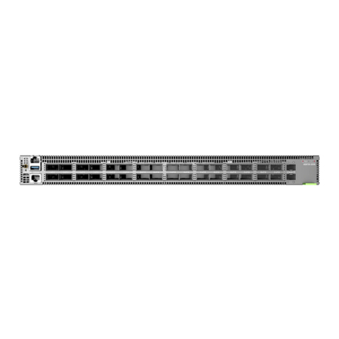
  9. Edge-Core DCS520 User manual

Edge-Core DCS520 User manual

This manual suits for next models

1

Other Edge-Core Switch manuals

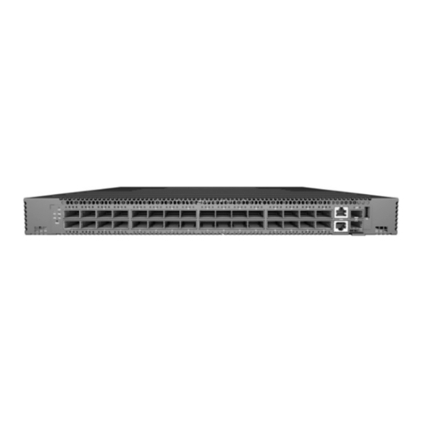
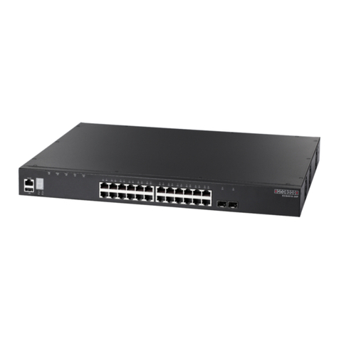
Edge-Core AS7326-56X User manual

Edge-Core

Edge-Core AS7326-56X User manual

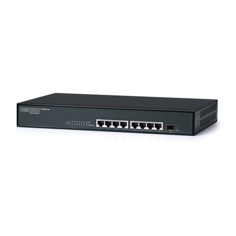
Edge-Core ECS2000-10T User manual

Edge-Core

Edge-Core ECS2000-10T User manual

Edge-Core ES4512C User manual

Edge-Core

Edge-Core ES4512C User manual

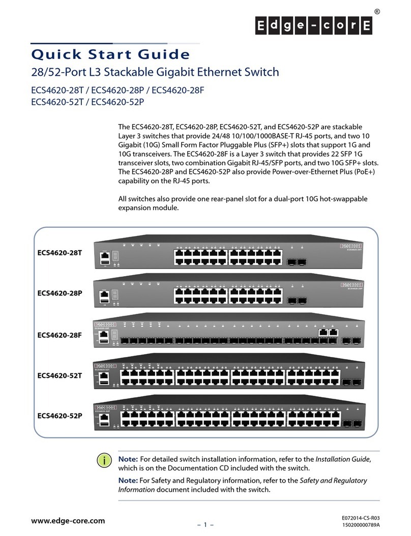
Edge-Core ECS4150-28T User manual

Edge-Core

Edge-Core ECS4150-28T User manual

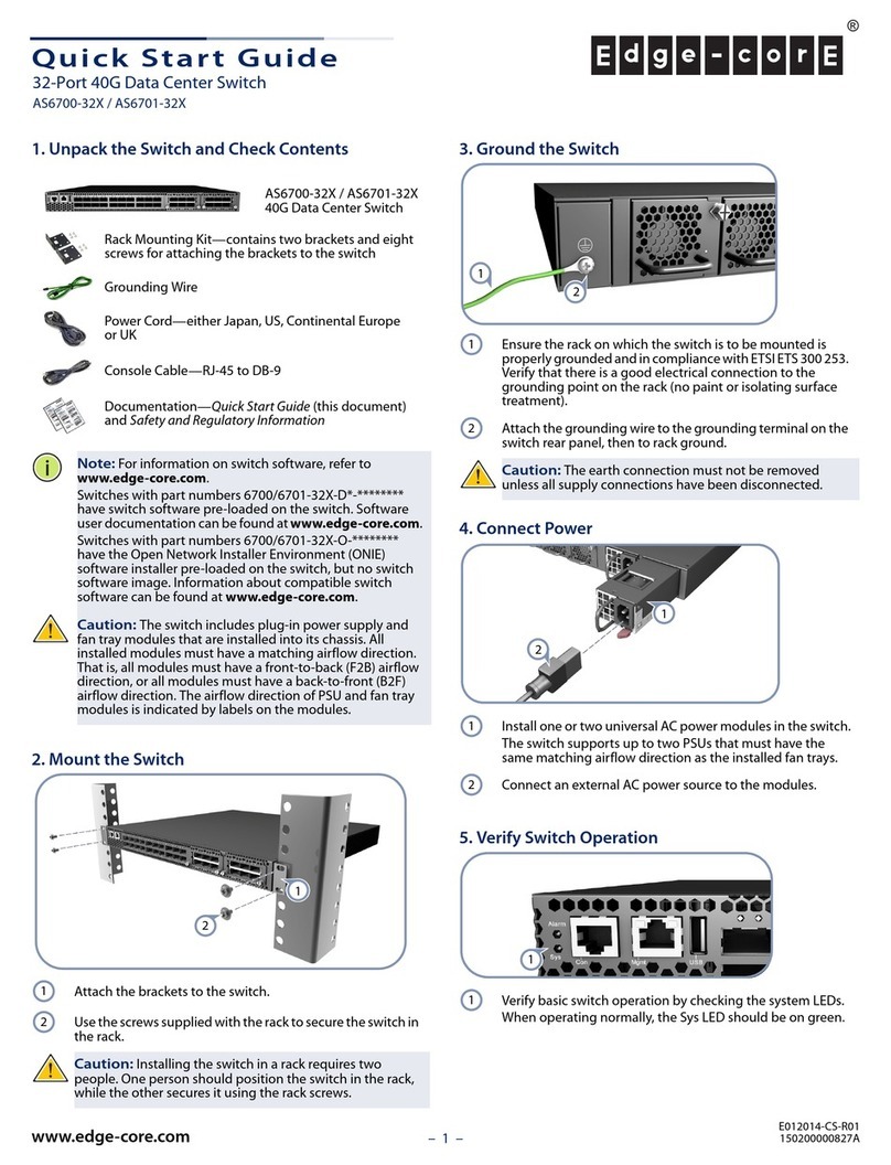
Edge-Core AS6712-32X User manual

Edge-Core

Edge-Core AS6712-32X User manual

Edge-Core AS4610-30T User manual

Edge-Core

Edge-Core AS4610-30T User manual

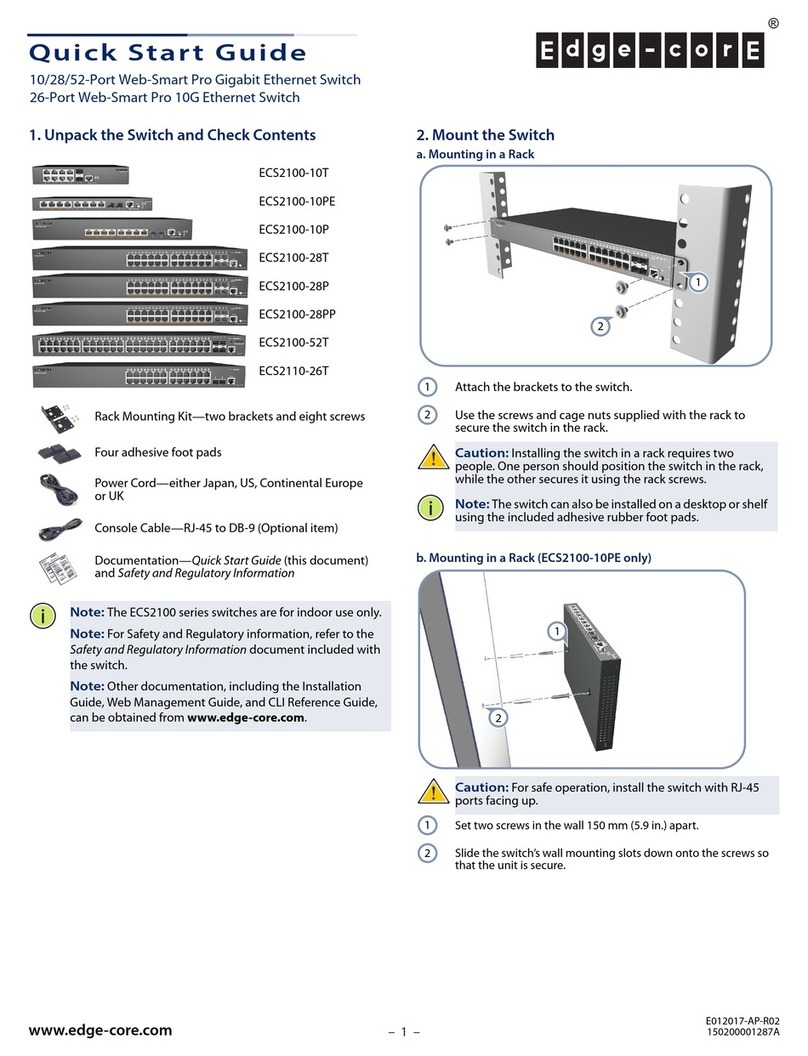
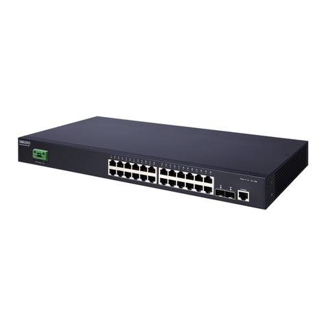
Edge-Core ECS2100-10P User manual

Edge-Core

Edge-Core ECS2100-10P User manual

Edge-Core ECS4310-26T Programming manual

Edge-Core

Edge-Core ECS4310-26T Programming manual

Edge-Core ES3528-WDM Programming manual

Edge-Core

Edge-Core ES3528-WDM Programming manual

Edge-Core ECS4110-28P User manual

Edge-Core

Edge-Core ECS4110-28P User manual

Edge-Core ES3510MA Programming manual

Edge-Core

Edge-Core ES3510MA Programming manual

Edge-Core ECS4110-28T User manual

Edge-Core

Edge-Core ECS4110-28T User manual

Edge-Core AS7712-32X Owner's manual

Edge-Core

Edge-Core AS7712-32X Owner's manual

Edge-Core AS7816-64X User manual

Edge-Core

Edge-Core AS7816-64X User manual

Edge-Core AS5610-52X User manual

Edge-Core

Edge-Core AS5610-52X User manual

Edge-Core AS5912-54X User manual

Edge-Core

Edge-Core AS5912-54X User manual

Edge-Core ECS4130-28T User manual

Edge-Core

Edge-Core ECS4130-28T User manual

Edge-Core ES4308-POE User manual

Edge-Core

Edge-Core ES4308-POE User manual

Edge-Core AS6701-32X User manual

Edge-Core

Edge-Core AS6701-32X User manual

Edge-Core ECS3510-52T User manual

Edge-Core

Edge-Core ECS3510-52T User manual

Edge-Core Wedge-16X-AC User manual

Edge-Core

Edge-Core Wedge-16X-AC User manual

Edge-Core AS7535-28XB User manual

Edge-Core

Edge-Core AS7535-28XB User manual

Edge-Core ECS2100-10T User manual

Edge-Core

Edge-Core ECS2100-10T User manual

Edge-Core ECS2100-10P User manual

Edge-Core

Edge-Core ECS2100-10P User manual

Popular Switch manuals by other brands

SMC Networks SMC6224M Technical specifications

SMC Networks

SMC Networks SMC6224M Technical specifications

Aeotec ZWA003-S operating manual

Aeotec

Aeotec ZWA003-S operating manual

TRENDnet TK-209i Quick installation guide

TRENDnet

TRENDnet TK-209i Quick installation guide

Planet FGSW-2022VHP user manual

Planet

Planet FGSW-2022VHP user manual

Avocent AutoView 2000  AV2000BC AV2000BC Installer/user guide

Avocent

Avocent AutoView 2000 AV2000BC AV2000BC Installer/user guide

Moxa Technologies PT-7728 Series user manual

Moxa Technologies

Moxa Technologies PT-7728 Series user manual

Intos Electronic inLine 35392I operating instructions

Intos Electronic

Intos Electronic inLine 35392I operating instructions

Cisco Catalyst 3560-X-24T Technical specifications

Cisco

Cisco Catalyst 3560-X-24T Technical specifications

Asante IntraCore IC3648 Specifications

Asante

Asante IntraCore IC3648 Specifications

Siemens SIRIUS 3SE7310-1AE Series Original operating instructions

Siemens

Siemens SIRIUS 3SE7310-1AE Series Original operating instructions

RGBLE S00203 user manual

RGBLE

RGBLE S00203 user manual

Thrustmaster FLIGHT SIMULATOR X quick guide

Thrustmaster

Thrustmaster FLIGHT SIMULATOR X quick guide

Southwire SURGE GUARD 41390 RVC troubleshooting guide

Southwire

Southwire SURGE GUARD 41390 RVC troubleshooting guide

Buhler Nivotemp NT 61 Brief instructions

Buhler

Buhler Nivotemp NT 61 Brief instructions

Kramer VS-41HDCP user manual

Kramer

Kramer VS-41HDCP user manual

Techly IDATA AU-270 user manual

Techly

Techly IDATA AU-270 user manual

Belkin F1U109 user manual

Belkin

Belkin F1U109 user manual

Emerson Rosemount 2521 Series quick start guide

Emerson

Emerson Rosemount 2521 Series quick start guide

manuals.online logo
manuals.online logoBrands
  • About & Mission
  • Contact us
  • Privacy Policy
  • Terms and Conditions

Copyright 2025 Manuals.Online. All Rights Reserved.

– 1 –
Quick Start Guide
E042023-CS-R02
150200002542A
25.6T Data Center Switch
AS9736-64D
1.
25.6T Data Center Switch
AS9736-64D
2. Rack mounting kit—2 front-post brackets, 2 rear-post brackets
and 24 screws
3. HVAC/IEC C20 1m power cord
4. Documentation—Quick Start Guide (this document) and Safety
and Regulatory Information
1. System LEDs
2. 2 x 10G SFP+ management ports
3.
64 x 400G QSFP56-DD ports
4.
RJ-45 console port
5. 1000BASE-T RJ-45 management port, USB
6. PSU 1
7. 2 x grounding screws (maximum torque 10 kgf-cm (8.7 lb-in)
8. 4 x fan trays
9. PSU 2
368
57
14
27
9
Fan Tray Replacement
1. Pull the handle release latch.
2. Remove fan tray from the chassis.
3. Install replacement fan with matching airflow direction.
PSU Replacement
1. Remove the power cord.
2. Press the release latch and remove the PSU.
3. Install the replacement PSU in a matching orientation.
(PSU 1 AC socket faces down, and PSU 2 AC socket faces up.)
PSU 1 PSU 2
Package Contents
Overview
FRU Replacement
1. System LEDs
LOC: Flashing Blue/Amber (switch locator)
STAT: Green (OK), Blinking Green (system booting), Amber (fault)
FAN: Green (OK), Amber (fault), Blinking Amber (too few fans
installed)
PSU1/PSU2: Green (OK), Amber (fault)
2. SFP+ 10G LEDs: Left: Green (10G link), Amber (1G link)
Right: Green (10G activity), Amber (1G activity)
3. RJ-45 MGMT LEDs: Left: Green (1G link), Amber (10/100M link)
Right: Green (1G activity), Amber (10/100M activity)
4. QSFP56-DD LEDs
400G (1 x 8 lanes 50G PAM4): 1 LED Blue
200G (2 x 4 lanes 50G PAM4): 2 LEDs Cyan
100G (4 x 2 lanes 50G PAM4): 4 LEDs Green
100G (1 x 4 lanes 25G NRZ): 1 LED Green
40G (1 x 4 lanes 10G NRZ): 1 LED Dark Green
50G (2 x 2 lanes 25G NRZ): 2 LEDs Red
25G (4 x 1 lane 25G NRZ): 4 LEDs Orange
10G (4 x 1 lane 10G NRZ): 4 LEDs Yellow
1233
4
1 2 3 4
www.edge-core.com

System/Port LEDs
Quick Start Guide
– 2 –
Mount the Device
Ground the Device
Connect Power
Make Network Connections
Warning:
For a safe and reliable installation, use only
the accessories and screws provided with the device. Use
of other accessories and screws could result in damage to
the unit. Any damages incurred by using unapproved
accessories are not covered by the warranty.
Avertissement:
Pour une installation sûre et fiable,
utilisez uniquement les accessoires et les vis fournies avec
l’appareil. L’utilisation d’autres accessoires et vis pourrait
endommager l’appareil. Les dommages causés par
l’utilisation d’accessoires non approuvés ne sont pas
couverts par la garantie.
Note:
The device has the Open Network Install Environment
(ONIE) software installer preloaded, but no software image.
Information about compatible software can be found at
www.edge-core.com.
Note:
The drawings in this document are for illustration only
and may not match your particular model.
Caution:
This device must be installed in a
telecommunications room or a server room where only
qualified personnel have access.
Attention:
Cet appareil doit être installé dans une salle de
télécommunications ou une salle de serveurs où seul le
personnel qualifié a accès.
1
1. Attach the Brackets
Use the included screws to attach the front- and rear-post brackets.
2. Mount the Device
Mount the device in the rack and secure it with rack screws.
2
Verify Rack Ground
Ensure the rack on which the device is to be mounted is properly
grounded and in compliance with ETSI ETS 300 253. Verify that there is
a good electrical connection to the grounding point on the rack (no
paint or isolating surface treatment).
Attach Grounding Wire
Attach a lug (not provided) to a #6 AWG minimum grounding wire
(not provided), and connect it to the grounding point on the device rear
panel. Then connect the other end of the wire to rack ground.
3
When the input voltage is 200-240 VAC or 240 VDC, install one or
two AC PSUs and connect them to the AC power source.
When the input voltage is 100-127 VAC, two AC PSUs must be
installed and connected to the AC power source.
4
400G QSFP56-DD Ports and 10G SFP+ Ports
Install transceivers and then connect fiber optic cabling to the
transceiver ports.
Alternatively, connect DAC or AOC cables directly to the slots.
Installation
Quick Start Guide
– 3 –
Make Management Connections
5
10/100/1000M RJ-45 Management Port
Connect Cat. 5e or better twisted-pair cable.
RJ-45 Console Port
Use an RJ-45-to-DB-9 null-modem console cable (not included) to
connect to a PC running terminal emulator software. Use a USB-to-
male DB-9 adapter cable (not included) for connections to PCs that do
not have a DB-9 serial port.
Configure the serial connection: 115200 bps, 8 characters, no parity,
one stop bit, 8 data bits, and no flow control.
Console cable pinouts and wiring:
Device’s RJ-45 Console Null Modem PC’s 9-Pin DTE Port
6 RXD (receive data) <---------------- 3 TXD (transmit data)
3 TXD (transmit data) ----------------> 2 RXD (receive data)
4,5 SGND (signal ground) ------------------ 5 SGND (signal ground)
Hardware Specifications
Size (WxDxH) 440 x 649.2 x 87 mm (17.32 x 25.56 x 3.43 in.)
Weight 21.5 kg (47.4 lb), with 2 PSUs and 4 fans installed
Temperature Operating: 0° C to 45° C (32° F to 113° F)
Storage: -40° C to 70° C (-40° F to 158° F)
Humidity Operating: 5% to 95% (non-condensing)
Power
Consumption
2100 Watts maximum
AC PSU
Input Power
Rating
100–127 VAC, 50/60 Hz, 12 A maximum
200–240 VAC, 50/60 Hz, 15 A maximum
HVDC: 240 VDC, 15 A maximum
Regulatory Compliances
Emissions EN 55032:2015+A1:2020 Class A
EN IEC 61000-3-2:2019+A1:2021 Class A
EN 61000-3-3:2013+A1:2019
FCC Class A
Immunity EN 55035:2017+A11:2020
IEC 61000-4-2/3/4/5/6/8/11
Safety UL (CSA 22.2 No 62368-1 & UL62368-1)
CB (IEC/EN 62368-1)