Citel EDAC User manual

EXPANDABLE DIGITAL TO ANALOG CONVERTOR
(EDAC)
Formerly the
EDAC
Installation Guide
Document Number 512-1090-001
Revision K0
Dated September 2011

EDAC Installation Guide
512-1090-001, Revision K0
Page 2 of 56
This page intentionally left blank

EDAC Installation Guide
512-1090-001, Revision K0
Page 3 of 56
This page intentionally left blank

EDAC Installation Guide
512-1090-001, Revision K0
Page 4 of 56
NOTE
This equipment has been tested and found to comply with the limits for a Class A digital device, pursuant
to Part 15 of the FCC Rules. These limits are designed to provide reasonable protection against harmful
interference when the equipment is operated in a commercial environment. This equipment generates,
uses and can radiate frequency energy, and if not installed and used in accordance with the instruction
manual, may cause harmful interference to radio communications. Operation of this equipment in a
residential area is likely to cause harmful interference in which case the user will be required to correct
the interference at their own expense.
If this equipment is shipped with filtered phone line, data or power cords, they must be used in series with
each equipped digital phone port. Failure to do so may jeopardize continued FCC Part 15 compliance.
Changes or modifications not expressly approved by MCK, a division of Citel Technologies, Inc. could
void the user’s authority to operate the equipment.
NOTICE
The manual described herein is copyrighted, with all rights reserved. Under copyright laws, this manual
may not be copied, in whole or in part, without the written consent of MCK Communications. The same
proprietary and copyright notices must be affixed to any permitted copies as were affixed to the original
manual. The documentation cannot be sold, given or loaned to another person or company without the
written consent of MCK, a division of Citel Technologies, Inc.
This product was designed and manufactured by MCK, a division of Citel Technologies, Inc. It was
designed to be attached to the Nortel Meridian 1, SL-1, SL-100 PBX or Norstar KSU systems, the NEC
Electra Professional KSU, NEAX 2000 or 2400, Alcatel 4200 or 4400, or Iwatsu ADIX PBX systems, the
Lucent Definity PBX, or the Aspect CallCenter only. If you have any questions, please contact MCK
Communications. This product is not supported or warranted by Nortel, NEC, Lucent, Aspect, Siemens,
Panasonic, Alcatel, or Iwatsu.
Meridian 1, SL-1, SL-100 and Norstar are registered trademarks of Nortel Networks. Electra Professional,
NEAX and Dterm are registered trademarks of NEC. Definity is a registered trademark of Lucent
Technologies. Reflexes is a registered trademark of Alcatel. ADIX is a registered trademark of Iwatsu.
CallCenter is a registered trademark of Aspect Telecommunications.
To order products or obtain technical information or support if you experience technical difficulties with
this product, please call or write MCK, a division of Citel Technologies.
© 2011 Citel Technologies, Inc.
221 Commerce Drive
Amherst, NY 14228
Telephone: 206-957-6270
Technical Support: 888-454-5828
Fax: 206-957-6275

EDAC Installation Guide
512-1090-001, Revision K0
Page 5 of 56
This page intentionally left blank
EDAC Installation Guide
512-1090-001, Revision K0
Page 6 of 56
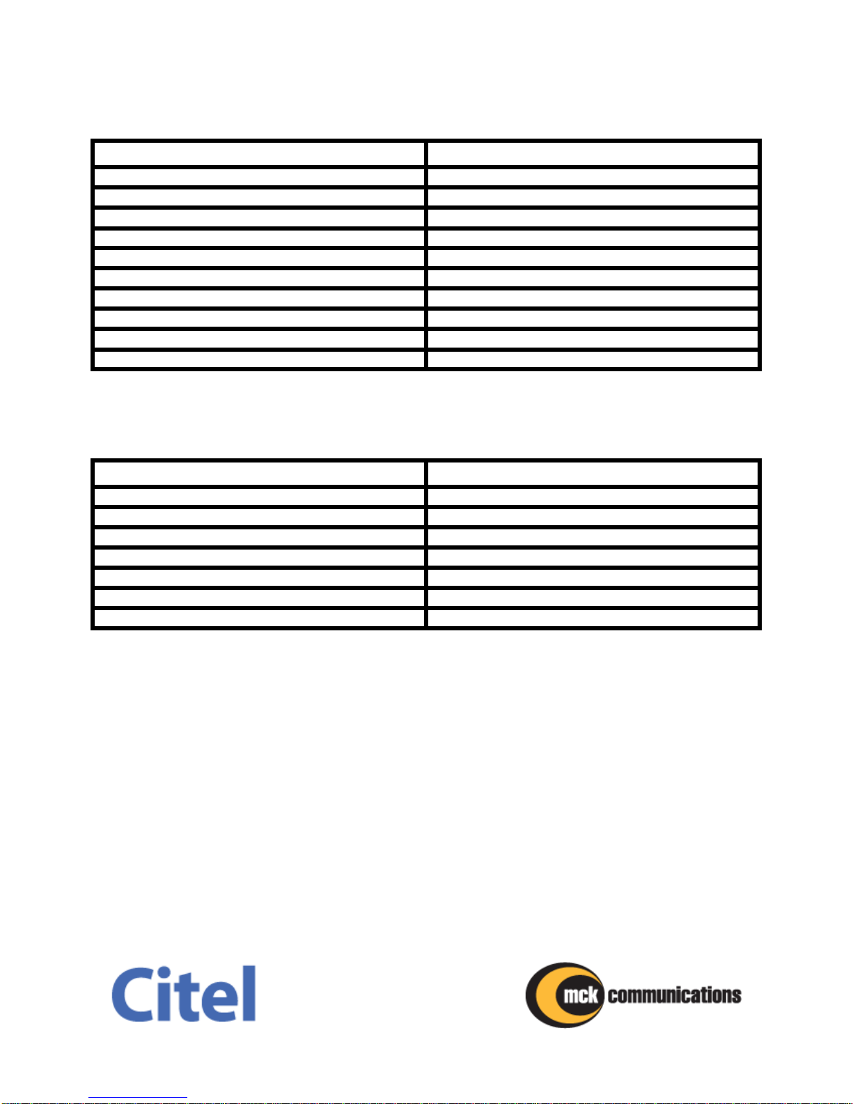
REVISION HISTORY
REVISION
ISSUE DATE
Revision A (Original Issue)
July 16, 1994
Revision B
May 25, 1995
Revision C
April 24, 1996
Revision D
September 9, 1996
Revision E
May 21, 1997
Revision F
February 23, 1998
Revision G
August 28, 1998
Revision H0
September 8, 2000
Revision J0
May 28, 2002
Revision K0
September 30, 2011
Total number of pages in this publication is 56 pages consisting of the following:
PAGE
REVISION
Cover
K0
Blank
K0
Note/Notice
K0
Blank
K0
Revision History
K0
Blank
K0
7-54
K0

EDAC Installation Guide
512-1090-001, Revision K0
Page 7 of 56
This page intentionally left blank

EDAC Installation Guide
512-1090-001, Revision K0
Page 8 of 56
Table of CONTENTS
Section/Title
PAGE
Chapter 1
Product Description………………………………………………………...
13
Overview……………………………………………………….............
13
EDAC Compatibility..………………………………………….............
14
EDAC Configuration.………………………………………….............
15
EDAC Product Numbers.…………………………………….............
16
Chapter 2
Functional Description……………………………………………………..
17
Indicator Lamps……………………………………………….............
18
RJ-21 (25-Pair) Connector…..……………………………….............
18
Cabling……………...………………………………………….............
18
Digital Input.…………………………..……………………….............
19
Analog Input………………………………..………………….............
19
EDAC Single Port Cards…..………………...……………….............
19
EDAC Duel Relay Cards…………………….……………….............
20
Base Board……………...…………………………………….............
21
EDAC Power Distribution Panel.…………………………….............
21
Single-Unit Power Supplies………………………………….............
22
Multi-Unit Power Supplies……...…………………………….............
22
Chapter 3
Installation……………..……………………………………………………..
23
Installing Port and Relay Cards…..………………………….............
23
Removing Port and Relay Cards…………………………….............
26
Setting Dip Switches………………………………………….............
27
Nortel Systems.…………..…………………………….............
28
NEC Systems……………………..…………………….............
29
Aspect Call Center.…………..………………………...............
30
Lucent Definity……………………..………………..…...........
31

EDAC Installation Guide
512-1090-001, Revision K0
Page 9 of 56
Lucent Merlin Magix….……………..………………..…...........
31
Panasonic…..……………………..…………………….............
32
Siemens…………..…………..………………………...............
33
Ericsson………...……………………..…………………...........
33
Alcatel...………...……………………..…………………...........
34
Iwatsu...………...……………………..…………………...........
35
Installing the EDAC Unit…………..………………………….............
36
Mounting……...………...……………..…………………...........
36
Wall Mounting….……………………..…………………..
36
Rack Mounting with Power Distribution...……………...
37
Wall Mounting with Power Distribution ……………......
39
Cross Connecting the Digital Input....…………………...........
40
Cross Connecting the Analog Output…………………...........
40
Cross Connecting Relays…………...…………………...........
40
Connecting Power………….………...…………………...........
42
Wall Mount….….……………………..…………………..
42
Rack Mount/Wall Mount (Distributed Power).………...
42
Chapter 4
Testing and Troubleshooting……………………………………………..
43
Testing……………………………...………………………….............
43
Troubleshooting……………………………………………….............
43
Checking for Improperly Aligned or Seated Cards.....………
45
Chapter 5
Warranty………………………..……………………………………………..
47
Chapter 6
49
Specifications..………………..……………………………………………..
49

EDAC Installation Guide
512-1090-001, Revision K0
Page 10 of 56
List of Figures
Figure
PAGE
1
Expandable Digital to Analog Convertor (EDAC)
13
2
EDAC Configuration Diagram
15
3
Front Panel
17
4
Indicator Lamps
18
5
EDAC Single Port Card
19
6
EDAC Dual Relay Card
20
7
Base Board
21
8
Single-Unit Power Supply
22
9
Multi-Unit Power Supply
22
10
Card Installation and Removal
25
11
EDAC Configured for Four Ports with Relays
25
12
User Configured DIP Switches
27
13
Recommended Wall Mounting
36
14
Non-Recommended Wall Mounting
36
15
Front and Back View of Rack Mount Installation
37
16
Power Distribution Module
38
17
DIN Power Cable
38
18
Wall Mount Installation with Power Distribution
39
19
Cross Connection Diagram for One Base Unit with 12 Port Cards
40
20
EDAC Power Input Receptacle PIN Diagram
50

EDAC Installation Guide
512-1090-001, Revision K0
Page 11 of 56
List of Tables
Table
PAGE
1
EDAC Compatibility
14
2
EDAC Product Numbers
16
3
Relay and Port Card Position Assignments
20
4
Switch Settings for Nortel SL-1, SL-100 or M-1 Systems
28
5
Switch Settings for Nortel Norstar Systems
28
6
Switch Settings for NEC Systems
29
7
Switch Settings for Aspect CallCenter
30
8
Switch Settings for Lucent Definity
31
9
Switch Settings for Lucent Merlin Magix
31
10
Switch Settings for Panasonic DBS-824 PBX
32
11
Switch Settings for Siemens PBX
33
12
Switch Settings for Ericsson PBX
33
13
Switch Settings for Alcatel PBX
34
14
Switch Settings for Iwatsu PBX
35
15
DIN Power Cable Connections
38
16
RJ-21 (25-Pair) Connector Pinout
41
17
Troubleshooting Guide
44
18
Power Input Receptacle Pinout
50
19
Regulatory Compliance
54

EDAC Installation Guide
512-1090-001, Revision K0
Page 12 of 56
This page intentionally left blank

EDAC Installation Guide
512-1090-001, Revision K0
Page 13 of 56
CHAPTER 1 —Product Description
Overview
The Expandable Digital to Analog Convertor (EDAC), shown in Figure 1, allows users
with Nortel, Lucent, NEC, Panasonic, Ericsson, Alcatel, Iwatsu, or Aspect digital
telephone systems to record conversations onto standard analog recording equipment.
In operation, the EDAC passively captures both sides of the telephone conversation and
sends the audio to the recorder only when a call is active.
The EDAC consists of a base unit and plug-in port cards, which allow a single EDAC to
handle up to twelve telephone lines. Optional relay cards may also be installed in the
base unit for recording systems which require contact closures to control start/stop
recording. DIP switches on the EDAC provide the flexibility to configure the system for a
variety of installations.
The EDAC utilizes a space saving design in a compact case measuring only 8 x 9.5 x
2.25 inches (20 x 24 x 6 cm). The unit can be installed as backroom equipment to
prevent unauthorized disconnection from the recording equipment. The EDAC case has
a flexible design which allows it to be mounted on a wall or within an equipment rack.
Figure 1. Expandable Digital to Analog Convertor (EDAC)

EDAC Installation Guide
512-1090-001, Revision K0
Page 14 of 56
EDAC Compatibility
Different models within the EDAC product family support the digital telephone systems
shown in Table 1. The shaded areas in the table indicate the telephone systems that
are supported by the EDAC models described in this document. Other EDAC models
are described in their respective installation guides.
Table 1. EDAC Compatibility
MANUFACTURER
PBX TYPE
PHONE TYPES
Nortel
Norstar
M7100, M7208, M7310, M7324,
T7100, T7208, T7316, T7316E
Nortel Standard
Meridian 1, SL-1, SL-100
M2006, M2008, M2009, M2012,
M2216, M2616, M2250, M3904,
M3905
Nortel Selective Record
Meridian 1 ONLY
M2216, M2616
Nortel Two-Button
Meridian 1 ONLY
M2216, M2616
Nortel Release Detect
Meridian 1 ONLY
M2006, M2008, M2009, M2012,
M2216, M2616
NEC
NEAX 2000, NEAX 2400,
NEAX 7400
(Line cards 16ELCH & 16ELCJ)
Dterm ® Series III & E
NEC
Electra Professional KSU
Electra Professional Series
NEC
8100, 8300 Series
DT310, DT330
Aspect
CallCenter
3010 & 3190 TeleSets
Avaya
Avaya IP Office
All 1400, 5400, 9500 Series
Lucent ***
Definity G3, G5, G6 (2-wire)
(Line cards TN2181 & TN2224)
All 6400, 8400 Series,
CallMaster III, IV, VI
Lucent ***
Definity (4-wire)
(Line cards TN754)
7400 Series,
CallMaster I, II, III, IV
Lucent
Merlin Magix
All 4400 Series
Siemens***
Hicom 150 E & 300 E –
Ref 6.4 or later
(150 E Line card: Q2901-X-G1/01)
(300 E Line card: SLMO Q2158-X000)
HICOM 100 E (Australia)
150: Office Point, Office Com,
Office Pro
300 Optiset; Entry 69660,
Basic 69668, Standard 69662,
Advance+ 69663
Panasonic
DBS-824 PBX
VB4400
Ericsson
MD110
200 and 210 Series
Alcatel
4200 & 4400 PBX
Reflexes Series 4023, 4034,
4035
Iwatsu
ADIX KTS
IX-8, 16, 24KTD,
1X-8, 16KTS,
1X-12KTD-2, IX-12KTS-2
*** Compatibility is determined by the digital line card not by phone type.

EDAC Installation Guide
512-1090-001, Revision K0
Page 15 of 56
EDAC Configuration
Figure 2 demonstrates the connectivity between the EDAC and the digital telephone
system. The EDAC bridges across each digital telephone line to be recorded and
provides a corresponding audio pair out to the recorder.
NOTE
Loop length is system dependent. See Cabling section for system specific distances.
Figure 2. EDAC Configuration Diagram
The EDAC monitors the digitized voice information carried on the telephone line and
reformats the digitized information into standard 600 ohm analog format required by
most recording equipment. The unit captures both sides of a conversation and sends
audio to the recorder only when a call is active. This is especially useful with the search
features of recorders that look for silent periods between conversations. Since there is
no open microphone, as with simple recording systems, recording occurs only during
active phone conversations. Therefore, office conversations held between calls are not
recorded and remain private. Port and relay cards are user installed, which allows the
system to be configured to meet site requirements, and later expanded as the need
arises. External AC to DC power supplies support installations in most parts of the
world.

EDAC Installation Guide
512-1090-001, Revision K0
Page 16 of 56
EDAC Product Numbers
Due to the numerous combinations of port, relay, and power requirements, EDAC
components are sold individually. This allows the customer to purchase only the
required components. Part numbers for the EDAC product line are listed below in Table
2. The shaded areas in the table indicate the telephone systems that are supported by
the EDAC models described in this document. Other EDAC models are described in
their respective installation guides.
Table 2. EDAC Product Numbers
ITEM
PART NUMBER
EDAC Base Unit (Nortel, NEC, Aspect)
500-1090-001
EDAC Base Unit (Lucent 2-Wire)
500-1092-001
EDAC Base Unit (Lucent 4-Wire)
500-1092-002
EDAC Base Unit (Panasonic)
500-1092-003
EDAC Base Unit (Ericsson)
500-1092-004
EDAC Base Unit (Selective Record)
500-1094-001
EDAC Base Unit (3-Button Selective Record)
500-1094-201
EDAC Base Unit (Siemens)
500-1092-001
EDAC Base Unit (Release Detect)
500-1094-002
EDAC Base Unit (Alcatel)
500-1092-007
EDAC Base Unit (Iwatsu)
500-1092-008
EDAC Port Card (Nortel)
300-3030-001
EDAC NE1 Port Card (NEC)
300-3030-002
EDAC Port Card (Aspect)
300-3030-003
EDAC Port Card (Lucent 2-Wire)
300-3032-003
EDAC Port Card (Lucent 4-Wire)
300-3032-007
EDAC Port Card (Panasonic)
300-3032-009
EDAC Port Card (Ericsson)
300-3032-010
EDAC Port Card (Siemens)
300-3032-005
EDAC Port Card (Alcatel)
300-3032-013
EDAC Port Card (Iwatsu)
300-3032-014
EDAC M1 Multi-Function Port Card (Selective Record, 3-Button
Selective Record, Release Detect)
300-3034-001
EDAC Dual Relay Card (Multi-Function)
300-3020-001
EDAC Power Supply, North American
500-1120-002
EDAC Multi-Unit Power Supply, North American
500-1120-005
EDAC Power Supply, Continental European
500-1120-001
EDAC Multi-Unit Power Supply, Continental European
500-1120-003
EDAC Power Distribution 19 inch Rack Mount Panel
500-1102-001
EDAC Power Distribution Wall Mount Module
500-1102-002
EDAC Power Distribution Cable
450-1102-001
NOTE: Power supplies are desktop style and come with mounting hardware.

EDAC Installation Guide
512-1090-001, Revision K0
Page 17 of 56
Chapter 2
FUNCTIONAL DESCRIPTION
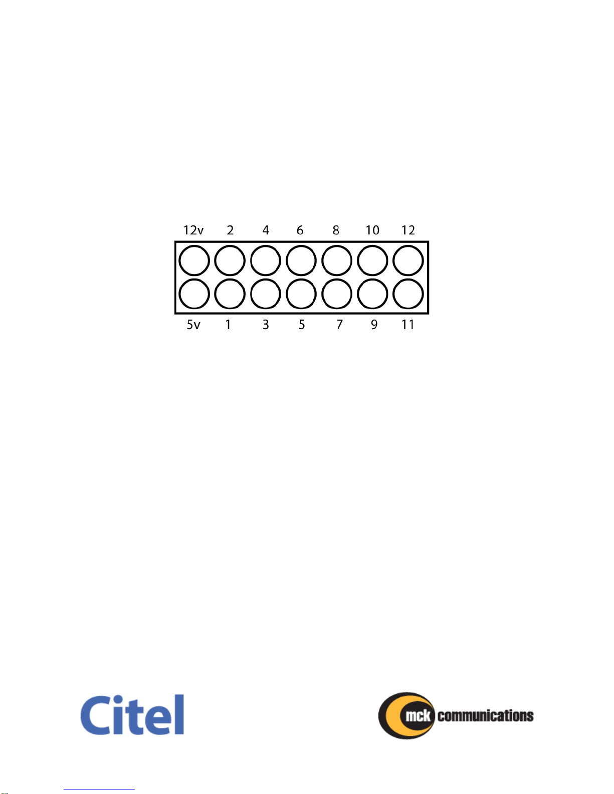
All connectors, controls and indicators are located on the front panel as shown in Figure
3. There are two connectors: a standard female 5-pin DIN connector for 5VDC and
12VDC power input and an RJ-21 (25-pair) male connector for port and recorder
interfacing. Four DIP switches allow the EDAC to be configured for a wide variety of
user needs. LEDs indicate power and port activity.
Figure 3. Front Panel
EDAC Installation Guide
512-1090-001, Revision K0
Page 18 of 56
Indicator Lamps
Two green lamps on the front of the unit indicate that the unit is receiving 5V and 12V
power levels. The other 12 lamps are red and illuminate when the associated telephone
set is active.
Figure 4 shows positions for each port’s LED. LEDs may illuminate where port cards
have been installed but are not cross-connected since port cards not cross-connected
do not receive idle code. When relay cards are installed, the associated indicator lamp
will not be lit.
Figure 4. Indicator Lamps
RJ-21 (25-Pair) Connector
An RJ-21 (25-pair) male connector provides access to the EDAC’s digital inputs, analog
outputs and relay contact pairs.
Cabling
To attach the EDAC unit to a user-furnished cross-connect block, the user must provide
a 25-pair, 24 AWG (0.5mm) standard twisted pair wire cable terminated with a female
RJ-21 connector on one end.
EDAC Installation Guide
512-1090-001, Revision K0
Page 19 of 56
Digital Input
The digital input of each port on the EDAC attaches in parallel to one digital telephone
port. The unit may be attached to the digital telephone port anywhere along the loop
between the switch and the telephone set. The distance between the line connection
and the EDAC unit (tap length) should be no more than 30 feet (9 meters). There should
be no line stubs (loose, non-terminated cables). Loop length limits range from 1,000 feet
(305 meters) to 2,500 feet (762 meters) depending on the system. Refer to Cabling
section on page 37 for more detail.
The EDAC interface adds very minimal loading of the digital telephone line and will not
affect normal telephone operation. The EDAC digital input is cross-connected in parallel
with the telephone’s digital signaling pair.
Analog Output
The analog output of each port on the EDAC is cross-connected to the analog input of
standard 600 ohm recording or monitoring equipment. The EDAC’s analog output is a
600 ohm pair with a nominal level of -12dBm. Both ends of the conversation are
included in the analog output.
The distance between the EDAC’s analog output and the recording equipment may
depend on the minimum input level required by the recorder. Typical recording
equipment should operate at a distance of up to 2,500 feet (762 meters) from the EDAC
with 24 AWG cable. It is recommended that the analog loop be as short as possible to
reduce the possibility of noise from nearby electrical equipment that may cause
interference in the recorded audio.
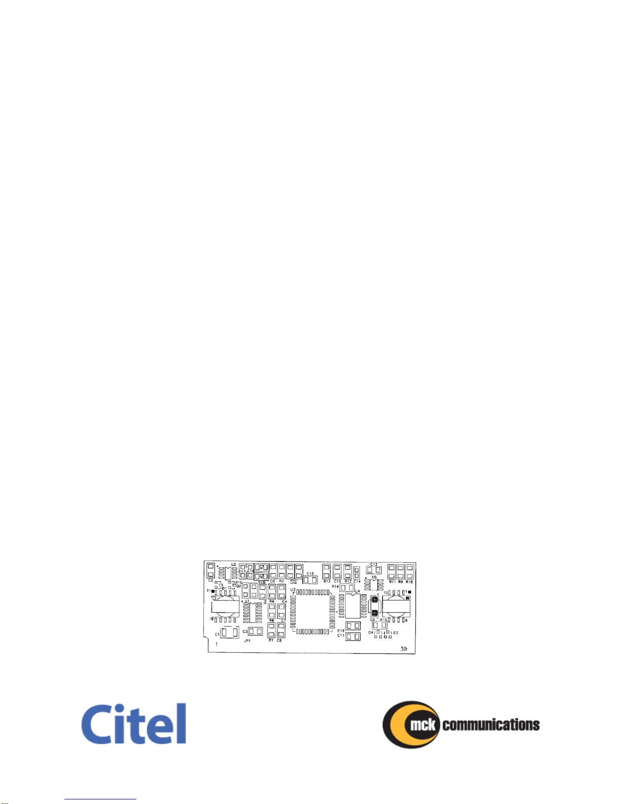
EDAC Single Port Cards
Single port cards, shown in Figure 5, mount into the SIMM sockets, labeled JP1, JP2 ...,
JP12, on the base board (see Figures 6 and 7 for more detail). Each port card services
one port on the PBX or KSU. These cards provide the main functionality for the EDAC.
Prior to installation or removal of cards, ensure that the unit power cord is disconnected.
Figure 5. EDAC Single Port Card
EDAC Installation Guide
512-1090-001, Revision K0
Page 20 of 56
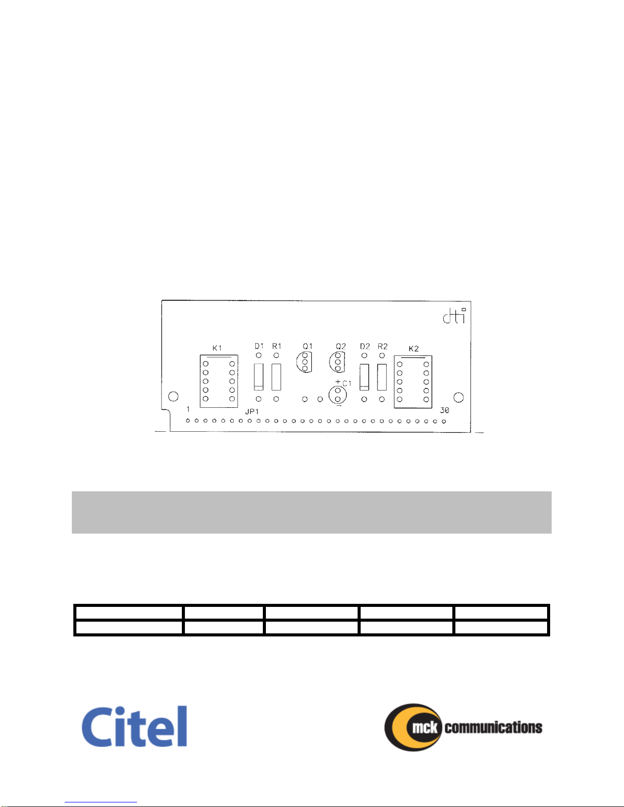
EDAC Dual Relay Cards
EDAC dual relay cards, as illustrated in Figure 6, provide dry contact closures for
installations where recording equipment is not voice activated and requires start/stop
control. Each relay card has two relays allowing one relay card to support one or two
ports.
The quantity of relay cards needed is dependent on the number of ports configured. For
example, a six-port configuration will require three relay cards. When the recording
device requires relay contacts, the maximum number of ports supported per EDAC
base unit is eight. When there is no conversation on the line, relay contact pairs are
normally open. When there is a conversation on the line, the relay contact closes to
start the recorder. If relay closures are needed, port cards may be installed in sockets 1-
8 and relay cards in sockets 9-12.
Figure 6. EDAC Duel Relay Card
WARNING
Relay cards are the same size and shape as port cards but should only be installed in
sockets JP9 - JP12 on the base unit.
Table 3 shows the port locations on the base board served by each relay card.
Table 3. Relay and Port Card Position Assignments
Relay Card Position
JP9
JP10
JP11
JP12
Port Card Position
JP1 & JP2
JP3 & JP4
JP5 & JP6
JP7 & JP8
Table of contents


