pro bel 3415 Owner's manual

ontents
1Introduction2
2onfiguration and operation4
.1Selecting the rear connector4
. Setting component output options5
.3Component level adjustment6
.4Status LEDs8
3Trouble shooting10
4OSMOS status monitoring12
5Specification14
6Ordering information16
Technical Manual 1
3415omponent Video Digital to Analogue onverter
1Introduction
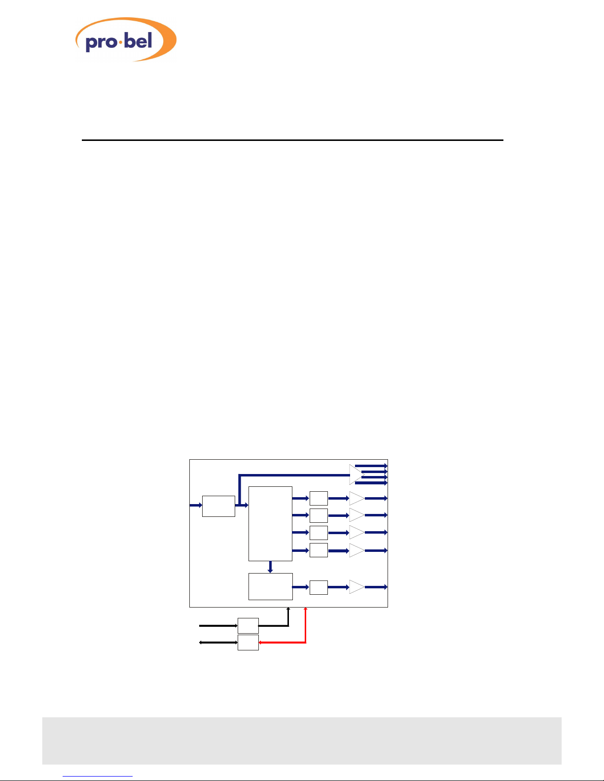
he 3415 is a precision 10 bit 270Mb/s component digital to analogue video
converter with full I U-R 601 filtering. he output is switchable for GBR or Y, Pb, Pr
with sync on Y/GBR and on a separate output. An output of composite analogue
video is provided to facilitate composite monitoring and four re-clocked and
buffered copies of the SDI input are provided with the 30mm rear panel. Vertical
interval information may be passed or blanked and most configuration settings can
be remotely controlled or monitored via the COSMOS interface.
he features available are:
•three analogue component outputs plus sync and analogue composite
monitoring
•additional four re-clocked buffered SDI outputs with the 30mm K3415-3 rear
connector
•10 bit 270Mbit/s processing
•automatic 525/625 operation
•adaptive input equalisation
•variable/calibrated (N10) gain
•setup (pedestal) on/off in 525
•VANC (Vertical Ancillary Data) deletion on/off
•COSMOS equipped
2chapter 1 revision .00
3415
DC POWER
AND COSMOS
STATUS DATA
POWER
REG
STATUS
MON
SDI INPUT
ANALOGUE
VIDEO
OUTPUTS
DAC
DAC
DE-SERIALISE &
DE-MULTIPLEX
Y/G
Pb/B
DAC
SYNC
REGEN
DIGITAL
PAL/NTSC
ENCODER
COMPOSITE
ANALOGUE
VIDEO
OUTPUT
EQUALISE
& RECLOCK
Pr/R
SYNC
CV
DAC
BUFFERED
SDI
OUTPUTS
he 3415 Component video digital to analogue converter

Technical Manual chapter 1 3
3415omponent Video Digital to Analogue onverter
2onfiguration and operation
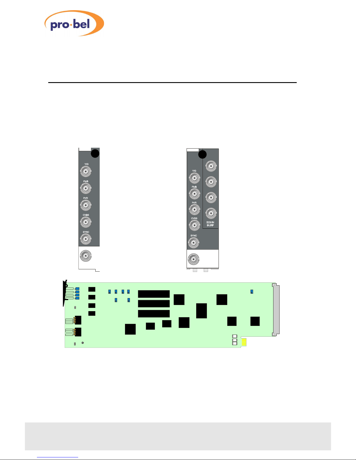
2.1Selecting the rear connector
he 3415 may be used with either the 20mm K3415-2 rear connector or the 30mm
K3415-3 rear connector which provides four outputs of the re-clocked buffered SDI
input.
Please refer to the installation chapter for help with installing modules and rear
connectors into the ICON frame.
4chapter revision .00
3415
K3415.3
SDI
IN
EMOTE
POWE
3415
SF2
SF1
Pb GAIN
V 3
GAIN VA
YPrPb/ GB
Y/G SYNC
INPUT E
525/60
SW1
EMOTE
VITC PASS
525 PED
SW2
Pr ADJ
Pb ADJ
Y ADJ
SYNC ADJ
Pr GAIN
V4
Pb DC
V 6
Pr DC
V 5
Y GAIN
V 2
Y DC
V 7
CVBS GAIN
V 1
SF3
he 3415 Component video digital to analogue converter
K3415.2
SDI IN
2.2Setting component output options
he analogue component output may be set in either Y, Pb, Pr or GBR formats. Syncs
may be added to the luminance (Y) or GBR signals and a 7.5 IRE pedestal may be
added in 525 operation to R, G, B and Y outputs.
he analogue outputs may be manually adjusted from front controls or left
calibrated according to SMP E/EBU N10. In addition the converter may be set to pass
or blank VANC (Vertical Ancillary Data). COSMOS allows many of these functions to
be controlled remotely.
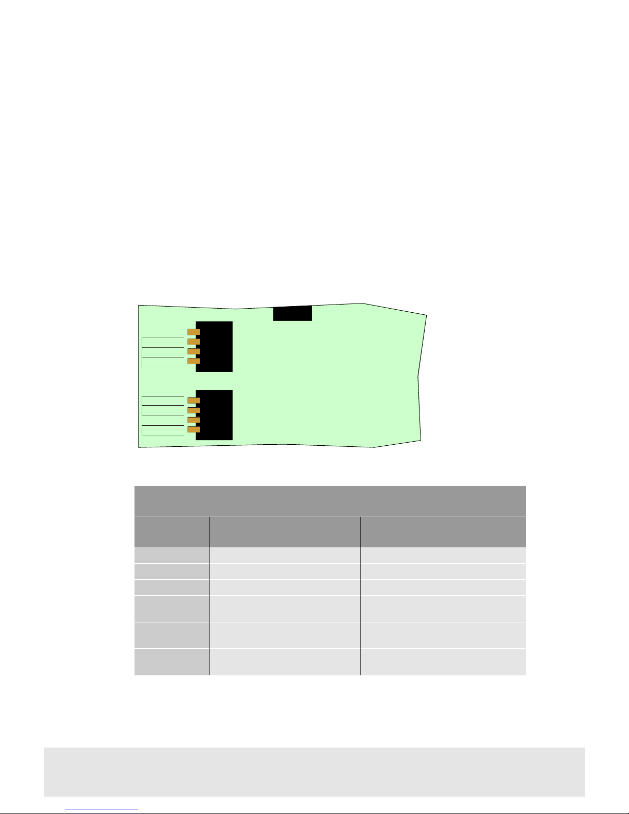
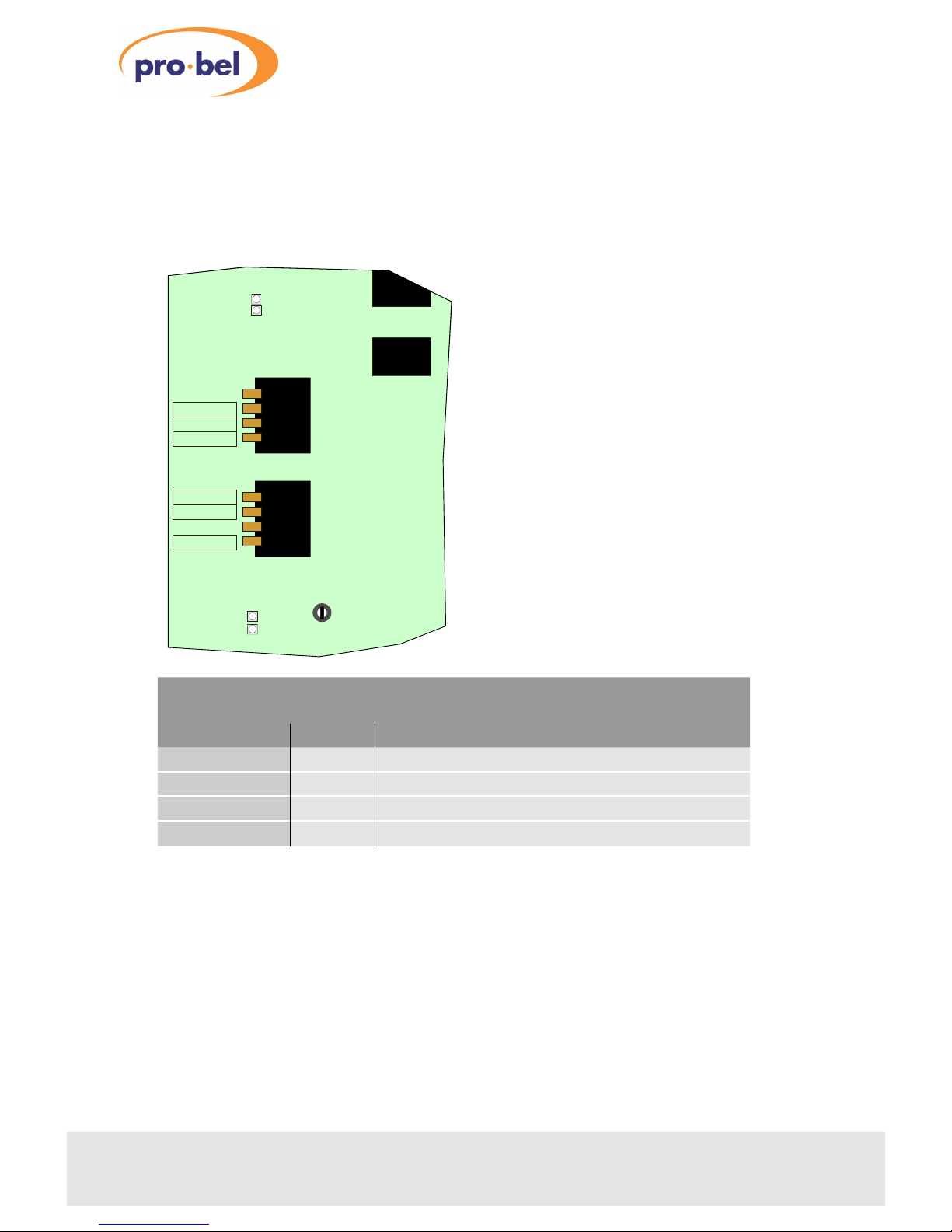
he front control dip switch settings are shown in the following diagram and
summarised in the table below.
Technical Manual chapter 5
3415omponent Video Digital to Analogue onverter
Front switch controls
SW1 & SW
lever name OFF functionON function
Y/G SYNC Sync not added to Y/GBRSync added to Y/GBR
YPrPb/RGB Y Pr Pb modeRGB mode
Gain Var Pre-set gainVariable gain (see 2-3)
5 5 PED No set-up (pedestal) added 7.5 IRE set-up added to Y/GBR outputs in
525 line mode
VITC PASS VANC (Vertical Ancillary Data) from
input deleted from analogue outputs
VANC (Vertical Ancillary Data) from input
passed to analogue outputs
REMOTE COSMOS remote configuration
disabled COSMOS remote configuration enabled
3415
GAIN VA
YPrPb/ GB
Y/G SYNC
SW1
EMOTE
VITC PASS
525 PED
SW2
Move switch levers
down for ON and up
for OFF

2.3omponent level adjustment
Gain adjustment is provided for the module analogue outputs for compatibility with
both Betacam and M-II formats. Adjustment ranges are shown relative to SMPE/EBU
N10 levels.
6chapter revision .00
3415
INPUT E
525/60
Pr ADJ
Pb ADJ
Y ADJ
SYNC ADJ
Front gain controls
NameDescription
Y ADJ Luminance gain ±1dB
Pb ADJ Pb gain +3dB to -1dB
Pr ADJ Pr gain +3dB to -1dB
SYNC ADJ Sync gain ±1dB
NOTES:
Signal gain adjustable in Gain Var mode only.
Other module adjustments are factory preset only and should not require
re-adjustment.
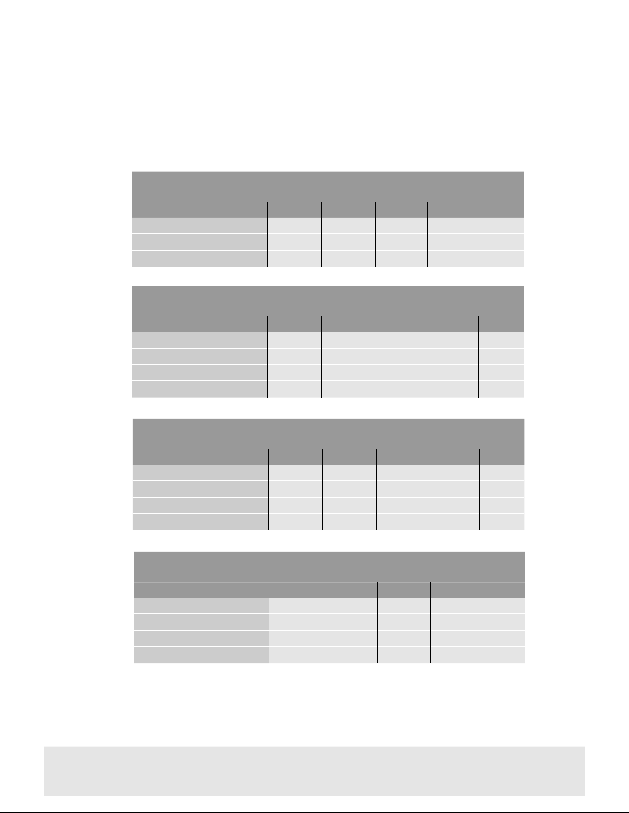
Standard component levels
he following tables summarise standard analogue component levels for SMPE/EBU
with and without set-up in 525.
Technical Manual chapter 7
3415omponent Video Digital to Analogue onverter
Y Pb Pr SMPTE/EBU N10 - no set-up
MaxMinVideoSyncP-P
Y (100% bars) 700mV0mV700mV-300mV1V
Pb, Pr (100% bars) 350mV-350mV700mV700mV
Y (75% bars) 525mV0mV525mV-300mV825mV
Pb, Pr (75% bars) 262.5mV-262.5mV525mV525mV
GBR
MaxMinVideoSyncP-P
SMPTE/EBU N10 700mV0mV700mV-300mV1V
55 no set-up 714mV0mV714mV-286V1V
55 with set-up 714mV54mV660mV-286V1V
Y Pb Pr 525 with set-up (Betacam®)
MaxMinVideoSyncP-P
Y (100% bars) 714mV54mV660mV-286mV1V
Pb, Pr (100% bars) 467mV-467mV934mV934mV
Y (75% bars) 549mV54mV495mV-286mV835mV
Pb, Pr (75% bars) 350mV-350mV700mV700mV
Y Pb Pr 525 with set-up (MII®)
MaxMinVideoSyncP-P
Y (100% bars) 700mV53mV647mV-300mV1V
Pb, Pr (100% bars) 324mV-324mV648mV648mV
Y (75% bars) 548mV53mV495mV-300mV848mV
Pb, Pr (75% bars) 243mV-243mV486mV486mV
2.4Status LEDs
he module is equipped with the following indicators to provide a means of
monitoring operation:
In local operation and 625/50 mode only the green POWER LED should be lit.
8chapter revision .00
3415
Indicators
LEDColourFunction
Input error RedInternal PLL not locked
55/60 YellowAutomatic line standard selection - illuminated in 525 mode
Remote YellowRemote COSMOS operation selected
Power GreenPower OK
EMOTE
POWE
GAIN VA
YPrPb/GB
Y/G SYNC
INPUT E
525/60
SW1
EMOTE
VITC PASS
525 PED
SW2

Technical Manual chapter 9
3415omponent Video Digital to Analogue onverter

3Trouble shooting
The Input Error LED is lit
•check that a valid serial digital video signal is connected to the rear connector
input BNC
Video black level is raised in 525 mode
•check that the 525 PED switch is not on if 7.5 IRE set-up is not required
Output levels are incorrect
•for calibrated N10 levels check that the GAIN VAR switch is off
The output is not synchronised in downstream equipment
•check the syncs requirement of the downstream equipment and supply separate
syncs, syncs on green or syncs on luminance as appropriate
The Power LED is not lit
•check mains power to the frame is turned on
•if necessary check the PSU as explained in the power supply section
•check the card is plugged in securely
•check to see if one of the re-settable fuses has operated. o do this turn the
power off, wait for thirty seconds and then restore the power.
10 chapter 3 revision .00
3415

Technical Manual chapter 3 11
3415omponent Video Digital to Analogue onverter

4OSMOS status monitoring
he 3415 module will provide the following information to the COSMOS status
monitoring controller (if fitted):
•standard selection (automatic)
•input error or PLL lock status
•pass VANC on/off
•525 set-up on/off
•Var/Fixed gain
•YPbPr/GBR selection
•Y/GBR sync on/off
•Power OK
•local/remote configuration select switch status
In remote mode, the following may also be controlled through COSMOS
•pass VANC on/off
•525 set-up on/off
•Var/Fixed gain
•YPbPr/GBR selection
In addition, the module is programmed with the following information, which can be
read by the status monitoring controller:
•module present
•module type
•module bar code
•module issue no
For further details of the Pro-Bel status monitoring system please refer to the
COSMOS status monitoring manual.
12 chapter 4 revision .00
3415

Technical Manual chapter 4 13
3415omponent Video Digital to Analogue onverter

5Specification
Inputs
Number and type:One 270Mb/s serial digital video input to EBU ech
3267E, SMPE 259M-C
Impedance: 75W unbalanced
Outputs
Number and type:hree analogue component video, 1Vpp nominal,
Y/G, Pb/B, Pr/R
One analogue mixed sync 2.0Vpp
One analogue composite video CVBS
Four re-clocked 270Mb/s SDI (only available with
30mm rear panel)
Impedance: 75W unbalanced
Performance
Input return loss:> 15dB 10MHz to 270MHz
Input equalisation:Automatic up to 300m Belden 8281 or similar cable
Output return loss:
(analogue)> 35dB to 4.3MHz
Output return loss:
(re-clocked SDI)> 15dB 10MHz to 270MHz
Gain:Error (cal mode) <1% any component
Stability 1 hour <1% any component
Pulse and bar response:Luminance 2 <0.3%K
Chrominance 4 <0.3%K
Sweep response:Luminance 0.1dB to 5.5MHz
Chrominance 0.1dB to 2.75MHz
Delay:Delay inequality <10ns between any components
Group delay ripple:Luminance ±3ns to 5.75MHz
Chrominance ±6ns to 2.75MHz
Noise:<-70dB rms 100Hz to 5MHz
14 chapter 5 revision .00
3415

On-card controls Y/GBR sync on/off
YPbPr/GBR
Set-up on/off 525
SMP E/EBU N10 levels/variable
Vertical blanking on/off
Luminance/Green gain
Pb/Blue gain
Pr/Red gain
Sync gain
LED indicators 525/60 - yellow
Input error - red
Remote configuration mode - yellow
Power OK - green
Technical Manual chapter 5 15
3415omponent Video Digital to Analogue onverter

6Ordering information
Part numberDescription
ICO-3415-2000Component video DAC, component and
composite outputs, 20mm
ICO-3415-3000Component video DAC, component, composite
and four SDI outputs, 30mm
16 chapter 6 revision 2.00
3415
Table of contents
Other pro bel Media Converter manuals


Popular Media Converter manuals by other brands


H&B
H&B TX-100 Installation and instruction manual

Bolin Technology
Bolin Technology D Series user manual

IFM Electronic
IFM Electronic Efector 400 RN30 Series Device manual

GRASS VALLEY
GRASS VALLEY KUDOSPRO ULC2000 user manual

Linear Technology
Linear Technology DC1523A Demo Manual

Lika
Lika ROTAPULS I28 Series quick start guide

Weidmuller
Weidmuller IE-MC-VL Series Hardware installation guide

Optical Systems Design
Optical Systems Design OSD2139 Series Operator's manual

Tema Telecomunicazioni
Tema Telecomunicazioni AD615/S product manual

KTI Networks
KTI Networks KGC-352 Series installation guide

Gira
Gira 0588 Series operating instructions

Lika
Lika SFA-5000-FD user guide