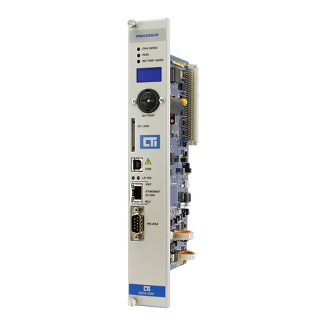
Cito System PC/104 User manual

MillenniumSeries
PC/104MotionControllers
User’sManual
C to Systems

NOTICE
This document contains proprietary and confidential information of Cito Systems, and is
protected by federal copyright law. The contents of this document may not be disclosed to
third parties, translated, copied, or duplicated in any form, in whole or in part, without the
express written permission of Cito Systems.
The information contained in this document is subject to change without notice. No part of
this document may be reproduced or transmitted in any form, by any means, electronic or
mechanical, for any purpose, without the express written permission of Cito Systems.
Copyright 2004 by Cito Systems
Navigator™ and C-Motion™are trademarks of Performance Motion Devices
ii

Warranty
Cito Systems warrants performance of its products to the specifications applicable at the
time of sale in accordance with Cito Systems' standard warranty. Testing and other quality
control techniques are utilized to the extent Cito Systems deems necessary to support this
warranty. Specific testing of all parameters of each device is not necessarily performed,
except those mandated by government requirements.
Cito Systems reserves the right to make changes to its products or to discontinue any
product or service without notice, and advises customers to obtain the latest version of
relevant information to verify, before placing orders, that information being relied on is
current and complete. All products are sold subject to the terms and conditions of sale
supplied at the time of order acknowledgement, including those pertaining to warranty,
patent infringement, and limitation of liability.
SafetyNotice
Certain applications using semiconductor products may involve potential risks of death,
personal injury, or severe property or environmental damage. Products are not designed,
authorized, or warranted to be suitable for use in life support devices or systems or other
critical applications. Inclusion of Cito Systems products in such applications is understood
to be fully at the customer's risk.
In order to minimize risks associated with the customer's applications, adequate design and
operating safeguards must be provided by the customer to minimize inherent procedural
hazards.
Disclaimer
Cito Systems assumes no liability for applications assistance or customer product design.
Cito Systems does not warrant or represent that any license, either express or implied, is
granted under any patent right, copyright, mask work right, or other intellectual property
right of Cito Systems covering or relating to any combination, machine, or process in which
such products or services might be or are used. Cito Systems' publication of information
regarding any third party's products or services does not constitute Cito Systems' approval,
warranty or endorsement thereof.
iii

Millennium Series PC/104 Motion Controller Manual
iv
RelatedDocuments
Navigator Motion Processor User’s Guide (MC2000UG)
How to set up and use all members of the Navigator Motion Processor family.
Navigator Motion Processor Programmer’s Reference (MC2000PR)
Descriptions of all Navigator Motion Processor commands, with coding syntax and
examples, listed alphabetically for quick reference.

Content
Warranty....................................……….........................………...............................…….iii
Safety Notice ...........................................................................………...................…….. iii
Disclaimer......................................…….........................................….……............…….. iii
Related Documents.............................................................................………................... iv
Table of Contents..............................................................................................………….. v
1. PC/104 Board Installation………………………………………...……7
1.1. Installation Sequence........................................................................................7
1.2. Components List...............................................................................................7
1.3. Required Hardware...........................................................................................7
1.4. Preparing the Board for Installation ….............................................................8
1.4.1. Setting the Host I/O Mode...............................................................9
1.4.2. Setting the Bus I/O Address...........................................................10
1.4.3. Setting the IRQ Level……............................................................11
1.5. 3mc-0x-Bx Connections Summary.................................................................12
1.6. 3mc-0x-BLx Connections Summary…..........................................................12
1.7. 3mc-0x-B/BLx Connections Summary….......................................................13
1.8. 3mc-0x-MSx Connections Summary..............................…............................14
1.9. 3mc-0x-S Connections Summary...................................................................15
1.10. Applying Power.....................................................................................…15
2. Software Installation…………………………………………………..16
2.1. Using EasyMotion Console............................................................................16
2.2. First Time System Verification.......………....................................................17
2.2.1. Step #1 Set the Motor Amplifier Type....................................…..18
2.2.2. Step #2 Initialize Commutation................................………….....18
2.2.3. Step #3 Check Commutation.................................……….…….. 19
2.2.4. Step #4 Set Filter Parameters....................................……….........20
2.2.5. Step #5 Make a Trajectory Move...........................…………....…20
3. Operation……………………………...……………………………….21
3.1. Card Overview.............................………………………………………...…21
3.2. Dual-Port RAM...............................…………………………………………22
3.3. Safety Features.............................………………………………………...…22
3.3.1. Hard Reset....................…………………………………..........…23
3.3.2. Soft Reset....................…………………………………...........…23
3.3.3. External Reset.............................……………………………...…23
3.3.4. Under Voltage Monitor.....................…………………….........…23
3.3.5. Watchdog timer..........................……………………………....…23
3.3.6. Reset Status Monitor..................………………………............…24
3.4. Card ID Number............................……………………………………….…24
4. Connecting Hardware………………………………………………....24
4.1. Motors Output Command Signals..........................……………………....…24
5

4.1.1. Analog Output Motor Command.............................…………..…24
4.1.2. PWM Output Motor Command............................…………….…25
4.1.3. Pulse and Direction Output Motor Command……………..…….25
4.2. Incremental Encoder.............................…………………………………..…25
4.3. Parallel Feedback Devices.....................…………………………….........…25
4.4. Home and Limit Switches......................…………………………….........…25
4.5. Amplifier Enable Outputs...........................……………………………....…26
4.6. Amplifier Fault Inputs.............................……………………………………26
4.7. Axis Out Signal.............................………………………………………..…27
4.8. General Purpose Digital I/Os.......................………………………….......…27
4.8.1. High power digital I/Os.................……………………............…27
4.9. Analog Inputs.............................………………………………………….…27
4.10. The Synch Signal Connector for Multiple Chip Synchronization……….28
4.11. Serial Transceiver...............................…………………………………...28
5. Appendices……………………………………………………………..30
5.1. Appendix A. PC/104 Motion Controller Electrical Reference.......................30
5.1.1. PC/104 Motion Card Layout................... .............………………30
5.1.2. PC/104 Motion Card Connectors...........................………….......31
5.1.2.1. Motion Processor Synchronization Signal
Connector (J1)…..……………………...………………..31
5.1.2.2. Serial Communication Channel Connector (J2) ..............31
5.1.2.3. Host Interrupt Signal Connector (J3) ...............................32
5.1.2.4. Motion Peripherals Connector (J7) .....................…….....32
5.1.2.5. External Power Supply Connector (J9) ............................33
5.1.2.6. Miscellaneous I/O Signals Connector (J12)………...…..33
5.1.3. PC/104 Motion Controller Jumpers & Switch Block Settings.….34
5.1.3.1. Setting the Host I/O Mode – JP7.............................…….34
5.1.3.2. Setting the Incremental Encoders Input
Signal – JP8 - JP11………………………………….…..35
5.1.3.3. Setting the Committed I/O Signal Voltage Supply
Source – JP12 & JP13………………………..……….…35
5.1.3.4. Setting the High Power Digital Output – JP14 & JP15....36
5.1.3.5. Setting the Analog Input Voltage Reference
Source – JP1 – JP4…...…….….………………………...36
5.1.3.6. Setting the Base Address and the IRQ Level – S1………36
5.2. Appendix B. Outputs to Motor Amplifiers................ ……....................……37
5.2.1. Brushed Servo Motors (MC2100 series)...............................…....37
5.2.2. Brushless Servo Motors (MC2300 series)................................….38
5.2.3. Brush & Brushless Servo Motors (MC2800 series).................….38
5.2.4. Microstepping Motors (MC2400 series).................................…...38
5.2.5. Stepper Motors (MC2500 series)………….............................…..39
5.3. Appendix C. Encoder Inputs.......................................................……………39
5.4. Appendix D. Opto-isolated Committed Inputs...........................................…39
5.5. Appendix F. PC/104 Motion Controller Signal Connections………..…..… 40
5.6. Appendix G. PC/104 Motion Controller Hardware Information.......…….... 42
6

1 PC/104 Board Installation
In addition to the PC/104 card, the Millennium motion controller includes storage media
(CD) with the C-MotionPlus software library and device drivers. C-MotionPlus is a full-
featured C/C++ language library, which simplifies the development of motion applications
for the Navigator chipsets.
1.1 Installation Sequence
For a normal installation of the Millennium controller, you will need to configure the 3mc-
0x-xx board for the PC system and motor hardware that you will connect it to.
Configuration of the 3mc-0x-xx board is described in detail in the section below entitled
"Preparing the board for installation"
Next you will need to connect your system's motors, encoders, amplifiers and sensors as
desired to operate your motion hardware. A description of the connections that are made for
the various Navigator chipsets is found in the "3mc-0x-xx Connections Summary" sections
[1.5 – 1.9].
The final step to finish the installation is to perform a functional test of the finished system.
This is described in the section entitled "First time system verification".
Once all of the above has been accomplished installation is complete. You can now exercise
your motion system.
1.2 Components List
The Millennium controller set contains the following components:
1) Millennium Controller PC/104 board
2) Storage media with:
• C-MotionPlus library (static and DLL)
• Device drivers
• Millennium Series PC/104 Motion Controller – User’s Manual
• Navigator Motion Processor User's Guide (pdf format file)
• Navigator Motion Processor Programmers Reference (pdf format file)
3) Documentation:
Millennium Series PC/104 Motion Controller – User’s Manual
If any of these components are missing, please contact Cito Systems directly, or your Cito
Systems representative.
1.3 Required Hardware
To install the Millennium series PC/104 motion board, you will need the following
hardware:
7

1) PC/104 platform: the minimum platform consists of an Intel (or compatible) processor,
80286 or better, 5MB of available disk space, CD-ROM drive. The recommended
platform is an Intel (or compatible) processor, Pentium or better, 5MB of available disk
space, 32MB of available RAM, and CD-ROM drive. The operating system may be
Windows95/98/Me/NT/2000/XP/CE or Linux. An asynchronous serial
communications port is optional for both the minimum and recommended platforms.
2) 1 to 4 pulse and direction, PWM, or analog-input amplifiers. The type of amplifier
depends on the controller’s chipset type.
3) 1 to 4 step motors or servo motors. These motors may or may not provide encoder
position feedback signals depending on the type of chipset being used.
4) Additional connectors, as required to connect the 3mc-0x-xx PC board to the amplifiers
and the servo motors. Dual male 50-pin header-type connectors will be needed to
interface to the 3mc-0x-xx board's signal cable, part number CAB-100_2x50.
1.4 Preparing the Board for Installation
The board provides the following user-settable hardware options:
Option Set using Default
PC/104 bus I/O Address switch bank S1, 1-4 340 (hex)
PC/104 bus IRQ # switch bank S1, 5-8 IRQ disabled
Host interface mode jumper JP7 PC/104 bus
Table 1-1. PC/104 motion controller board default settings.
The host interface mode jumpers will not need to be changed unless it is desired that the
card be operated in serial mode. If operated in serial mode, a special adapter board is
required.
The following diagram shows the location of the jumper JP7:
8

Figure 1-1. Settable jumpers and connectors
If you need to change the default setting values from the Table 1-1, or are not sure if they
need to be changed, the following sections explain more about these settings.
1.4.1. Setting the Host I/O Mode
The PC/104 motion controller supports two different communication modes. This is shown
in the following table:
Mode Description
PC/104
mode The motion processor accepts instructions and data as full 16-bit words, using
the entire 16-bit data path
Serial port The motion processor accepts instructions through an asynchronous serial
port.
The figure below shows how the JP7 jumper should be installed to select the host mode.
PC/104 mode is the default. Shading indicates the location of the jumper.
9

serial port PC/104 parallel
1.4.2. Setting the PC/104 bus I/O address
The PC/104 motion card occupies 16 consecutive I/O addresses on the PC/104 bus,
starting at the "base address", and ending at the base address+F (hex). For example for the
default base address, which is 340 (hex), the total used range of addresses is 340 (hex) – 34F
(hex).
The I/O port base address should be chosen so that it doesn’t conflict with any other
devices using addresses in the range 300h-3FFh. Certain of these addresses are reserved for
specific peripherals, as shown in the following table (not all will be present in a given
system):
Portaddress Device
300-377h available
378-37Fh LPT1
380-3Afh usually available
3B0-3DFh VGA
3E0-3E7h available
3E8-3Efh COM3
3F0-3F7h Hard disk controller
3F8-3FFh COM1
Switch block S1, switches 1 - 4 determine the PC/104 bus base address. In the table below
switches, which should be on are indicated as such. A blank space in the table indicates the
switch should be set off (or left).
Address S1-1 S1-2 S1-3 S1-4
300h on on on on
310h on on on
320h on on on
330h on on
10

340h on on on
350h on on
360h on on
370h on
380h on on on
390h on on
3A0h on on
3B0h on
3C0h on on
3D0h on
3E0h on
3F0h
The default I/O port address is 340 hex (1-4: on, on, off, on)
For more detailed info on the I/O addresses used by the motion controller board, see
Appendix A, "PC/104 Motion Controller Electrical Reference", section 5.1.3.6.
1.4.3. Setting the IRQ level
The PC/104 controller board allows the motion chipset's HostIntrpt signal (used by the
chipset to signal special events) to generate a PC/104 interrupt that can be processed by
interrupt handling routines in the PC/104-based control software. The specific interrupt
(IRQ) that is generated can be programmed on the Millennium board using S1 switches #5-
8. The PC interrupt is generated when the chipset's HostIntrpt signal transitions from high
to low.
The table below shows the IRQs that are selectable and the associated S1 switch settings. If
no IRQ generation is desired than the "IRQ disabled" option should be selected. A blank
space in the table indicates the switch should be off (down).
IRQ# S1-5 S1-6 S1-7 S1-8
3 on on on on
5 on on on
7 on on on
10 on on
11 on on on
IRQ
disabled
The default IRQ setting is "IRQ disabled"
11

1.5 3mc-0x-Bx Connections Summary
The following table summarizes the connections provided and expected by the Millennium
PC/104 board when a MC2140 chipset is installed. Although the MC2140 supports up to
four axes any number of axis between 1 and 4 may be connected.
Chipset: MC2100 series
Maximum # of Axes: 4
Encoder Input Type: Incremental encoder
Encoder Input Signals:
(per axis) A quadrature channel input
B quadrature channel input
Index pulse channel input
# motor output channels:
(per axis) 1
Amplifier Output Signals
(per axis, if PWM sign,
magnitude used)
PWM Direction
PWM magnitude
Amplifier Output Signals
(per axis, if PWM 50/50 used) PWM magnitude
Amplifier Output Signals
(per axis, if analog output used) Differential analog out (DAC output)
Other Control Signals:
(per axis) Home signal channel input
Positive limit switch input
Negative limit switch input
Fault input
AxisOut output
Miscellaneous Signals: GND
+5 V (for encoder power)
For a complete description of the PC/104 card connectors and interfacing
requirements see Appendix A "PC/104 Motion Controller Electrical Reference".
1.6 3mc-0x-BLx Connections Summary
The following table summarizes the connections provided and expected by the Millennium
PC/104 board when a MC2340 chipset is installed. Although the MC2340 supports up to
four axes any number of axis between 1 and 4 may be connected.
Chipset: MC2300 series
Maximum # of Axes: 4
Encoder Input Type: Incremental encoder
Encoder Input Signals:
(per axis) A quadrature channel input
B quadrature channel input
Index pulse channel input
12

# motor output channels:
(per axis) 2 or 3 depending on motor output
selected and # phases
Amplifier Output Signals
(per axis, if PWM 50/50 used) PWM magnitude (phase A)
PWM magnitude (phase B)
PWM magnitude (phase C)
Amplifier Output Signals
(per axis, if analog output used) Analog out (phase A)
Analog out (phase B)
Hall inputs: Hall (phase A)
Hall (phase B)
Hall (phase C)
Other Control Signals:
(per axis) Home signal channel input
Positive limit switch input
Negative limit switch input
Fault input
AxisOut output
Miscellaneous Signals: GND
+5 V (for encoder power)
For a complete description of the PC/104 card connectors and interfacing
requirements see Appendix A "PC/104 Motion Controller Electrical Reference".
1.7 3mc-0x-B/BLx Connections Summary
The following table summarizes the connections provided and expected by the Millennium
PC/104 board when a MC2840 chipset is installed. Although the MC2840 supports up to
four axes any number of axis between 1 and 4 may be connected. Since this chipset allows
controlling a combination of brush and brushless servomotors, two pairs of each motor type
can be used.
Chipset: MC2800 series
Maximum # of Axes: 4
Encoder Input Type: Incremental encoder
Encoder Input Signals:
(per axis) A quadrature channel input
B quadrature channel input
Index pulse channel input
# motor output channels:
(per axis) 1, 2 or 3 depending on motor output
selected and # phases
Amplifier Output Signals
(per axis, if PWM sign,
magnitude used)
PWM Direction
PWM magnitude
Amplifier Output Signals
(per axis, if PWM 50/50 used) PWM magnitude (phase A)
PWM magnitude (phase B)
PWM magnitude (phase C)
13

Amplifier Output Signals for
brush type motors
(per axis, if analog output used)
Differential analog out (DAC output)
Amplifier Output Signals for
brushless type motors
(per axis, if analog output used)
Analog out (phase A)
Analog out (phase B)
Hall inputs: Hall (phase A)
Hall (phase B)
Hall (phase C)
Other Control Signals:
(per axis) Home signal channel input
Positive limit switch input
Negative limit switch input
Fault input
AxisOut output
Miscellaneous Signals: GND
+5 V (for encoder power)
For a complete description of the PC/104 card connectors and interfacing
requirements see Appendix A "PC/104 Motion Controller Electrical Reference".
1.8 3mc-0x-MSx Connections Summary
The following table summarizes the connections provided and expected by the Millennium
PC/104 board when a MC2440 chipset is installed. Although the MC2440 supports up to
four axes any number of axis between 1 and 4 may be connected.
Chipset: MC2400 series
Maximum # of Axes: 4
Encoder Input Type: Incremental encoder
Encoder Input Signals:
(per axis) A quadrature channel input
B quadrature channel input
Index pulse channel input
# motor output channels:
(per axis) 2 or 3 depending on motor output
selected and # phases
Amplifier Output Signals
(per axis, if PWM 50/50 used) PWM magnitude (phase A)
PWM magnitude (phase B)
PWM magnitude (phase C)
Amplifier Output Signals
(per axis, if analog output used) Analog out (phase A)
Analog out (phase B)
14

Other Control Signals:
(per axis) Home signal channel input
Positive limit switch input
Negative limit switch input
Fault input
AxisOut output
Miscellaneous Signals: GND
+5 V (for encoder power)
For a complete description of the PC/104 card connectors and interfacing
requirements see Appendix A "PC/104 Motion Controller Electrical Reference".
1.9 3mc-0x-S Connections Summary
The following table summarizes the connections provided and expected by the Millennium
PC/104 board when a MC2540 chipset is installed. Although the MC2540 supports up to
four axes any number of axis between 1 and 4 may be connected.
Chipset: MC2500 series
Maximum # of Axes: 4
Encoder Input Type: Incremental encoder
Encoder Input Signals:
(per axis) A quadrature channel input
B quadrature channel input
Index pulse channel input
# motor output channels:
(per axis) 1
Amplifier Output Signals:
(per axis) Pulse
Direction
Other Control Signals:
(per axis) Home signal channel input
Positive limit switch input
Negative limit switch input
Fault input
AxisOut output
Miscellaneous Signals: GND
+5 V (for encoder power)
For a complete description of the PC/104 card connectors and interfacing
requirements see Appendix A "PC/104 Motion Controller Electrical Reference".
1.10 Applying Power
Once you have connected the board to the desired number of external amplifiers and motor
encoders, hardware installation is complete and the board is ready for operation.
Upon power up, the motion controller will be in a reset condition. In this condition no
motor output will be applied until the chipset is initialized (see next section on software for
15

details). Therefore, the motors should remain stationary. If the motors do move or jump,
power down the board and check the amplifier and encoder connections. If anomalous
behavior is still observed, call Cito Systems, or your local representative for assistance.
2 Software Installation
On the storage media (CD) provided with the Millennium series PC/104 motion
controller there is a motion functions library called C-MotionPlus. This library contains
functions that are commands for the motion processor installed in the controller. The
user is responsible for writing a program to control motors motion and serving specific
application. In the following sections [2.2.1. – 2.2.5] are samples of the functions to
perform some basic moves.
The C-MotionPlus software library provided by Cito Systems supersedes the C-Motion
supporting the Navigator motion processors. C-MotionPlus provides interfaces to the C
functions as well as to the methods of C++ classes. It also has an interface to the TCL
scripting language. Additionally, this library allows communicating with multiple cards
on the bus at the time and invoking directly from a terminal window all the functions on a
local computer or remote one via network or RS-232/RS-485 link. The library supports
functions specific to Millennium series motion control boards.
It can be used in the Windows and Linux operating systems environment.
2.1 Using EasyMotion Console
EasyMotion is an application software package that can be purchased from Cito Systems for
easy and fast setting of a motion system. It contains a set of tools that help and assist in
configuring the motion card. One of the tools is a Motion Console that works as a terminal
interface allowing direct calling of the C-MotionPlus library functions. This way, without
writing a single line of code one can talk to the board and quickly verify the system.
16

Figure 2-1. Motion Console - EasyMotion command interface
2.2 First Time System Verification
To verify that the Millennium board has been properly installed, it is useful to have each axis
of the system perform a short move.
For the MC2100 parts to perform this simple sequence it is necessary to specify two items:
• the motor amplifier type (PWM sign/mag, PWM 50/50, or analog)
• the filter gains
For the MC2300 parts it is necessary to specify these two items as well as to initialize the
motor commutation.
The following table summarizes this. Note that the step #'s reference specific steps, which
are detailed in the next section.
Chipset Step # Operation
MC2100 1 Set amplifier type (PWM
sign/mag, PWM 50/50, DAC)
4 Set filter parameters
5 Make a trajectory move
17

MC2300 1 Set amplifier type (PWM 50/50,
DAC)
2 Initialize commutation
3 Check Commutation
4 Set filter parameters
5 Make a trajectory move
Only perform the setup step sequences indicated above for the chipset installed on your board.
To start verification use the following Navigator commands
SetActualPosition 0
Update
SetKp 25
Refer to the “Programmers Reference Manual” for a full list of commands.
It is assumed that you will check out each axis of your system one at a time. Then to check
out other axes enter a new axis number and check that axis out entirely, etc.
2.2.1. Step #1 Set the Motor Amplifier Type
The card must be told what type of motor output mode to use, PWM sign/mag, PWM
50/50, or DAC. This can be set using the command SetOutputMode. Assuming the axis you
want to exercise is #1, you would use the command "SetOutputMode" followed by the
output mode: 0 for DAC, 1 for PWM sign/mag, and 2 for PWM 50/50. For example to
specifiy the output mode as PWM 50/50 the following command would be used:
SetOutputMode 2
2.2.2. Step #2 Initialize Commutation
Note: This sections applies to MC2300 and MC2800 chipsets only.
For the motor to be controlled properly using the MC2300, the chipset must select and
possibly initialize the commutation phasing. If you will be using Hall-based commutation
then no initialization is necessary. Simply specify this to the chipset using the command:
SetCommutationMode 1
No other commands are necessary and you may proceed to step #3.
If you will be commutating using a sinusoidal technique you must initialize the commutation
phasing. There are two ways this can be done. You will need to decide whether to initialize
using Hall-based or algorithmic methods. See the Navigator User's Guide for more
information on this.
Each of these two phase initialization methods requires a separate sequence, as follows (note
that // indicates a comment and should not be typed in):
Hall-based initialization command sequence:
SetPhaseInitializeMode 1 // set phase initialize mode to 'Hall-based'
SetNumberPhases x // where x is 2 or 3 depending on type of motor
InitPhase
18

Algorithmic-based initialization command sequence:
SetPhaseInitializeMode 0 // set phase initialize mode to 'algorithmic'
SetMotorMode 0 // places axis in open loop mode, required for algorithmic init.
SetNumberPhases x // x is 2 or 3 depending on type of motor
SetPhaseCounts yyyy // yyyy is # of encoder counts per elec. cycle
SetPhaseInitializeTime zzzz // zzzz is # of chipset cycles to initialize for
SetMotorCommand wwww // wwww is motor command.
InitPhase
To determine the values of x, yyyy, zzzz, and wwww you should refer to the Navigator
User's Guide, "commutation" section.
If your system has one or more of the following conditions present then the above
sequence will need to be expanded. To handle such systems you will need to use the
SetSignalSense command as well as the SetPhasePrescale command. Call Cito
Systems for assistance
1) One or more Hall signals must be inverted to commutate or initialize the
commutation correctly
2) # of encoder counts per electrical cycle exceeds 32,767
2.2.3. Step #3 Check Commutation
Note: This sections applies to MC2300 and MC2800 chipsets only.
After phase initialization has been completed it is useful to check the smoothness of the
motor rotation in open loop mode to verify that the motor phasing initialization and
commutation is correct. To do this use the following command sequence:
SetMotorMode 0 // set axis for open loop operation
SetMotorCommand xxxx // xxxx is the motor command from 0 to 32,767 to output
Update
The 'xxxx' value represents the fraction of the value 32,768 of total power that will be
applied to the motor. For example, a value of 1,000 sends roughly 3% of the total power to
the motor.
When the motor mode is set off, the motor is not under servo control. Beware that
the motor may spin rapidly after a motor command value is applied. Use small values
and increase slowly.
After this command sequence the motor should smoothly spin in one direction or the other.
The motor command is a signed number and the sign controls the rotation direction. When
a positive motor command is given the motor should rotate in the positive (increasing
encoder counts) direction. If the motor spins roughly, in the wrong direction, or if it moves
a short distance and then abruptly stops there may be a problem with the commutation.
Check your wiring and re-test. Once the motor is spinning smoothly in both directions
19

under open loop control re-enable closed-loop servo control by executing the following
command:
SetMotorMode 1
2.2.4. Step #4 Set Filter Parameters
For motion to occur, some amount of feedback gain must be specified. Initially use just a
proportional gain with a very low value between 1 and 25. Later you can add integral or
derivative gains as well as feedforward gains if desired. The following sequence shows how
to set the P, I, and D terms of the filter and how to 'update' them, making them active.
SetKp xxxx // xxxx is the desired proportional gain
SetKd yyyy // yyyy is the desired derivative gain
SetKi zzzz // zzzz is the desired integral gain
Update // make thee values active.
It is not necessary to specify all 3 gains. Just Kp, followed by an Update can be specified, just
a Kd, etc...
Important note:
When exercising the motor use extreme caution. It is the responsibility of the
user to observe safety precautions at all times.
2.2.5. Step #5 Make a Trajectory Move
To test that the motor is being driven properly, set up and execute a small trapezoidal move.
Specify a small distance of (for example) 5,000 counts, and a low velocity and acceleration of
(for example) 10,000 counts/sample time, and 10 counts/sample time2respectively. With a
cycle time of 400 µsec, these values correspond to roughly 381 counts/sec, and 954
counts/sec2, respectively.
Whatever profile values you use, be sure that they are safe for your system.
Here is the command sequence to use:
SetProfileMode 0 // Sets current profile mode to trapezoidal
SetPosition xxxx // xxxx is the desired destination position
SetVelocity yyyy // yyyy is the desired maximum velocity
SetAcceleration zzzz // zzzz is the desired acceleration
SetDeceleration wwww // wwww is the desired deceleration
Update // execute the move
After entering this sequence of commands you should see the axis smoothly move for about
15 seconds (if the suggested values are used and the cycle time of the chipset is 400 µsec). If
you do not see the axis moving, or if the axis jumps rapidly in one direction or the other,
there may be a problem with the board or software settings. Re-check and review the board
setup procedures, as well as the exerciser parameter settings.
20
Table of contents
