Citronic 170.341 User manual
®
ST-SERIE
170.341 / 170.344 / 170.347
NEAR FIELD POWERED STUDIO MONITOR
OWNER’S MANUAL

®
CAUTION: TO REDUCE THE RISK OF ELECTRIC
SHOCK, DO NOT REMOVE COVER (OR BACK).
NO USER SERVICEABLE PARTS INSIDE.
REFER SERVICING TO QUALIFIED SERVICE
PERSONNEL.
Warning: To reduce the risk of fire or electric
shock, do not expose this unit to rain or
moisture.
The lightning flash with an arrowhead symbol
within an equilateral triangle, is intended to alert the
user to the presence of uninsulated dangerous
voltage within the product’s enclosure that may be
of sufficient magnitude to constitute a risk of electric
shock to persons.
The exclamation point within an equilateral triangle
is intended to alert the user to the presence of
important operating and maintenance (servicing)
instructions in the literature accompanying
the product.
Do not place this unit on an unstable cart,
stand or tripod, bracket or table. The unit may fall,
causing serious injury to a child or adult
and serious damage to the unit. Use only with a
cart, stand, tripod, bracket or table recommended
by the manufacturer or sold with the unit. Any
mounting of the device on a wall or ceiling should
follow the manufacturer instructions and should use
a mounting accessory recommended by the
manufacturer.
An appliance and cart combination should be
moved with care. Quick stops, excessive force and
uneven surfaces may cause the appliance and cart
combination to overturn.
Read and follow all the safety and operating
instructions before connecting or using this unit.
Retain this notice and the owners manual for future
reference.
All warnings on the unit and in its operating
instructions should be adhered to.
Do not use this unit near water; for example, near a
bath tub, washbowl, kitchen sink, laundry tub, in a
wet basement or near a swimming pool.
The unit should be installed so that its location or
position does not interfere with its proper
ventilation. For example, it should not be
situated on a bed, sofa, rug or similar surface that
may block the ventilation openings; or placed in a
built-in installation, such as a bookcase or cabinet,
that may impede the flow of air through its
ventilation openings.
The unit should be situated from heat sources such
as radiators, heat registers, stoves or other devices
(including amplifiers) that produce heat.
The unit should be connected to a power supply
outlet only of the voltage and frequency marked on
its rear panel.
The power supply cord should be routed so that it is
not likely to be walked on or pinched, especially
near the plug, convenience receptacles, or where
the cord exits from the unit.
Unplug the unit from the wall outlet before cleaning.
Never use benzine, thinner or other solvents for
cleaning. Use only a soft damp cloth.
The power supply cord of the unit should be
unplugged from the wall outlet when it is to be
unused for a long period of time.
Care should be taken so that objects do not fall,
and liquids are not spilled into the enclosure
through any openings.
This unit should be serviced by qualified service
personnel when: The power cord or the plug has
been damaged; Objects have fallen, or liquid has
been spilled into the unit; The unit has been
exposed to rain or liquids of any kind; The unit does
not appear to operate normally or exhibits a marked
change in performance; The device has been
dropped or the enclosure damaged.
DO NOT ATTEMPT SERVICING OF THIS UNIT
YOURSELF. REFER SERVICING TO QUALIFIED
SERVICE PERSONNEL
Upon completion of any servicing or repairs,
request the service shops assurance that only
Factory Authorized Replacement Parts with the
same characteristics as the original parts have
been used and that the routine safety checks have
been performed to guarantee that the equipment is
in safe operating condition.
REPLACEMENT WITH UNAUTHORIZED PARTS
MAY RESULT IN FIRE

®
Introduction
Congratulations on your Citronic purchase! Welcome to the growing family of Citronic owners.
Growing demands on music recording industry professionals have created the need for better monitor
performance at more affordable prices. The 170.341/344/347 Series class of Powered Studio Monitors was
created to address these needs. Please take a few moments to review the information in this guide.
Safety
For your safety and to ensure correct operation of this product, please take a moment to read the safety
precautions opposite this page.
Caution
Never remove the rear panel of these powered monitors. To do so could result in electric shock. A qualified
technician should preform any repair or service to the electronics.
This product is capable of producing sounds at a volume that could be damaging to hearing and result in
permanent hearing loss over an extended period of time.
Unpacking and Visual Inspection
It is rare that a unit is damaged during shipping. However, if this does happen, contact shipping company
immediately. Keep the original carton and packing material for future shipping, and to preserve your warranty!
Systems Control
SYSTEM VOLUME
The input sensitivity is adjusted (counterclockwise reduces sensitivity) with the rear
panel mounted System Gain control. Adjustment range is from -30dB to +6dB.
Factory preset gain is +6dB, which should suffice for most conditions. Normally
adjustments would only be made if you're using your monitor in a surround system
and need to balance levels or if your monitor send is too hot and not adjustable.
®
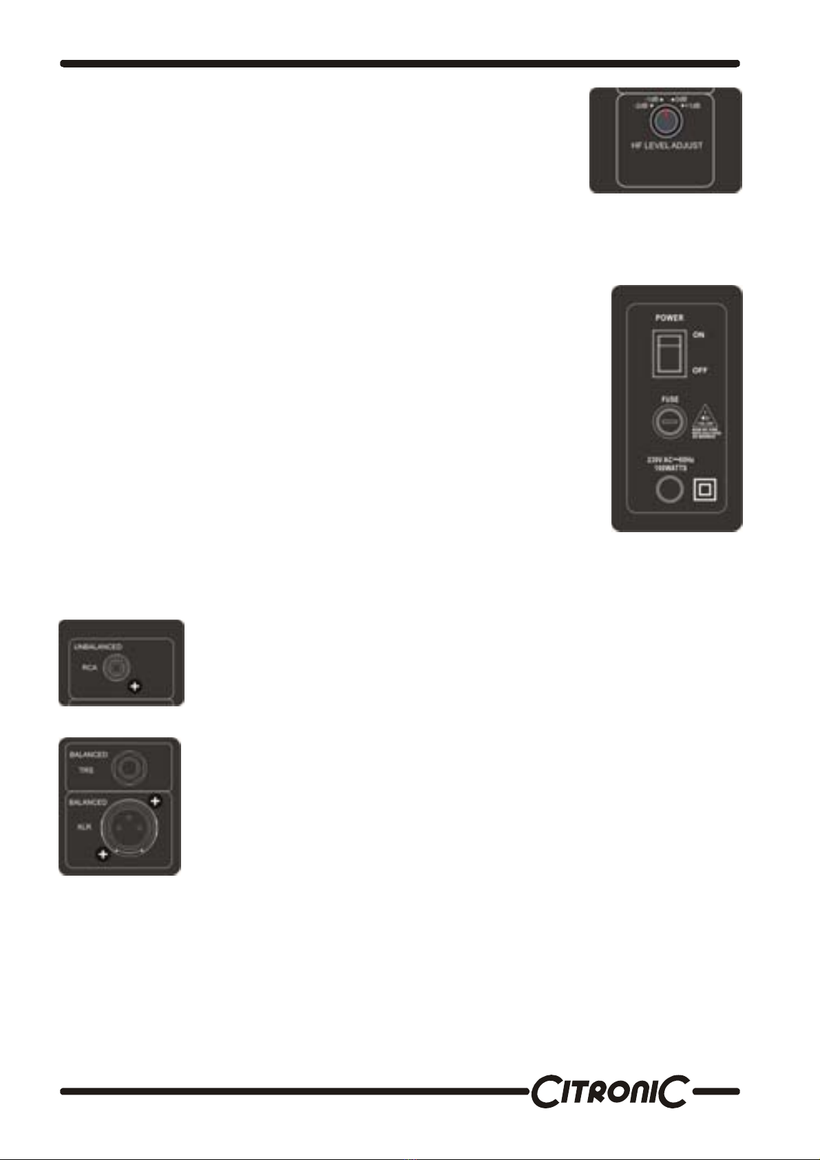
HF ADJUSTMENT
High Frequency Adjustment is through a rear panel mounted 4-position rotary switch.
Range of control is +1dB, Flat, -1dB ,or -2dB shelving above 2 kHz.
Factory setting for your is flat (switch is in 0dB position). Room acoustics may dictate
which type of adjustment you need to make to retain a flat frequency response from
the monitor. (See additional information in Installing Your Monitors section on page
4.)
Connecting Your System
POWERING ON
All connections should be made, all faders and controls should be set at their minimum
levels, and all other equipment should be powered on prior to powering on your
170.341/344/347 monitors.
The power On/Off switch is located on the rear panel and is internationally marked to
indicate the operational status. ( 1 ) = ON and ( O ) = OFF. A blue LED illuminates on
the front baffle when power is applied.
CHANGING FUSES
Under normal operation the fuses should not blow. A blown fuse usually indicates an
overload or fault condition. To change the fuse, remove the power cord, pry off the fuse
block with a small flathead screwdriver and change the blown fuses.
Refer to specifications page for fuse current ratings.
If the fuses blow immediately upon power up, this indicates a fault condition and the
monitor should be returned to Citronic dealer for repair.
AUDIO INPUTS
The XLR and TRS are balanced inputs where as the rca input is an unbalanced input.
UNBALANCED
BALANCED
10K OHMS BALANCED; PIN 2 + TIP = HIGH, PIN 3 + RING = LOW, PIN 1 + SLEAVE = GROUND
Installing Your Monitors
The close-field monitor, by definition, reduces room interaction. This can be compared to the conventional
stereo configuration or the large monitor arrangement in a recording studio where sounds emanating from the
monitor are reflecting off ceilings, walls, and floors greatly affect the sound quality. By shortening the path to the
ear, the close-field monitor offers a tremendous amount of flexibility, allowing the sound to become less
susceptible to differing room conditions. The ability to adjust the high frequency characteristics is equally
important to help compensate for room irregularities and achieve the highest sound accuracy. (See HF
Adjustments.)
®
A room that is heavily dampened would typically require a high frequency boost. Likewise, reducing the high
frequencies can alter a reverberant room.
Placing the monitor close to a rear wall, sidewall, or a corner will reinforce the low frequencies. Generally
speaking, if you move them two to three feet away from walls and corners, you'll hear less low frequency
interaction (excluding any interaction with the mixing console).
Positioning Your Monitors
Positioning your monitors correctly in the studio is critical to their performance. Typically, they should be placed
so that that the listening position is fully "covered" with all monitors resting on the same horizontal plane. A great
way to test a monitor for its imaging capability is to play back a CD or DVD recorded acoustically in stereo (or
one recorded in surround sound if you have a surround sound set-up). We recommend acoustic music because
it represents the spectrum of sound.) You can adjust the angle of each monitor by listening for dead spots.
Keep in mind, changing the angle or position of a monitor will change the sound.
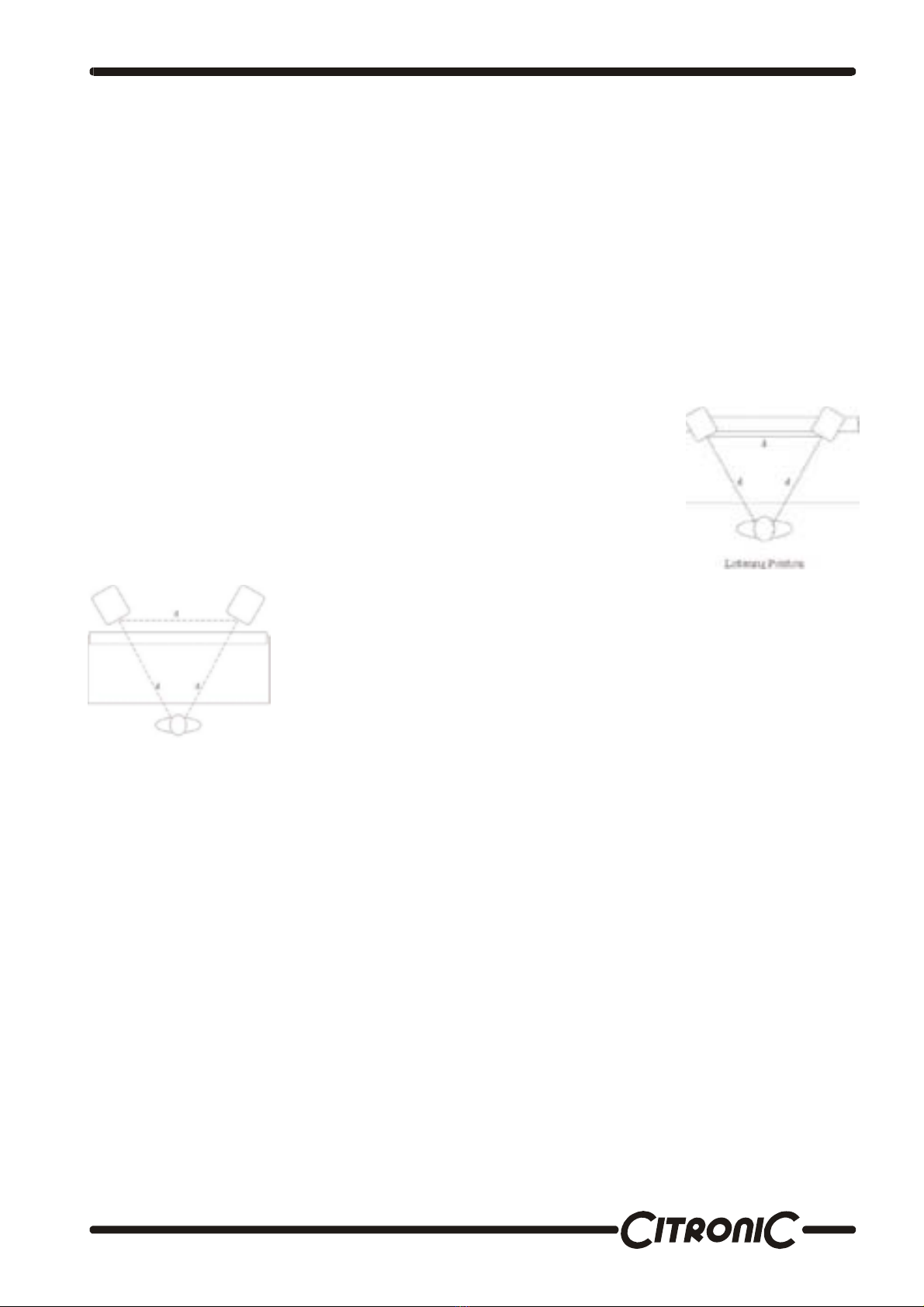
2-CHANNEL SET-UP
Close-Field Configuration
In a control room situation, the monitors are often times placed on the meter bridge
or in a close-field listening position. Initial placement starts by measuring out a
simple equilateral triangle (all three sides equal in length) with the apex at the centre
of the listening position (as shown in Figure)
as an "overlay" for the stereo installation. In this configuration, the Left and Right
monitors are each placed at a 60º angle Equidistant from the listening position.
Mid-Field Configuration
This configuration is basically the same as the Close-Field set-up. It is normally
used with larger monitors or when the monitors are too large or heavy for the meter
bridge. This set-up has the potential For a larger sweet spot and better spatial
imaging. Make sure that the height of the woofer is above height of the console.
Once the monitors have been placed. You need to adjust the SYSTEM GAIN pots (see page 2) for each monitor
so that all channels have exactly the same SPL output at the listening position. This can be done simply by
listening to each channel one at a time and adjusting for relative levels we recommend using an SPL meter and
filtered noise (pink noise) to test each channel independently. Simply take a reading from each monitor,and then
adjust all the monitors to match your lowest SPL reading. Your system levels should now be balanced for multi-
channel surround.
The most significant thing to remember is that each room presents its own set of acoustic variables. You’ll want
to experiment a bit to arrive at the best possible sound for your room.
IMPORTANT NOTE: Your 170.341/344/347 Powered Monitor was originally packaged in a specially designed
carton and included special packing materials. Please save these items they should be used when transporting
your monitors.

®
To see more products in the range visit….
www.citronic.com
Specifications
170.341 170.344 170.347
Frequency Response 53 Hz – 20kHz ±2.0dB 50 Hz – 20kHz ±2.0dB 45 Hz – 20kHz ±2.0dB
High Frequency Driver 1” Soft Dome 1” Soft Dome 1” Soft Dome
Low Frequency Driver 5” Aramid Glass Fiber 6.5” Aramid Glass Fiber 8” Aramid Glass Fiber
Cabinet Dimensions(HxWxD) 280 x 190 x 225mm 320 x 225 x 265mm 380 x 265 x 305mm
Net Weight (each) 7.2Kg 9.4Kg 12.4Kg
Amplifier
Power Rating (HF/LF) 15 watts/35 watts 15 watts/50 watts 15 watts/75 watts
Signal to Noise (HF/LF) 82dB/90dB 82dB/90dB 82dB/90dB
T.H.D%(HF/LF) 0.05% / 0.02% 0.05% / 0.02% 0.05% / 0.02%
Input Impedance
Balanced 10K Ohm 10K Ohm 10K Ohm
Unbalanced 10K Ohm 10K Ohm 10K Ohm
Crossover
Crossover Frequency 3kHz 2.6kHz 2.4kHz
Subsonic Filter 45Hz 40Hz 35Hz
FUSE 5mm x 20mm 0.8A 1A 1.6A
This manual suits for next models
2
Table of contents
Other Citronic Speakers manuals

Citronic
Citronic CX-2008 User manual

Citronic
Citronic CV8A User manual

Citronic
Citronic CASA-8A User manual

Citronic
Citronic ST5 User manual

Citronic
Citronic CT ACTIVE User manual

Citronic
Citronic ULTIMA CX-LIVE Series User manual

Citronic
Citronic CUBA Series User manual

Citronic
Citronic CS-6004 User manual


