Civintec Cidron Slimline User manual

CIDRON QR
Installation guide
Cidron Slimline QR Reader

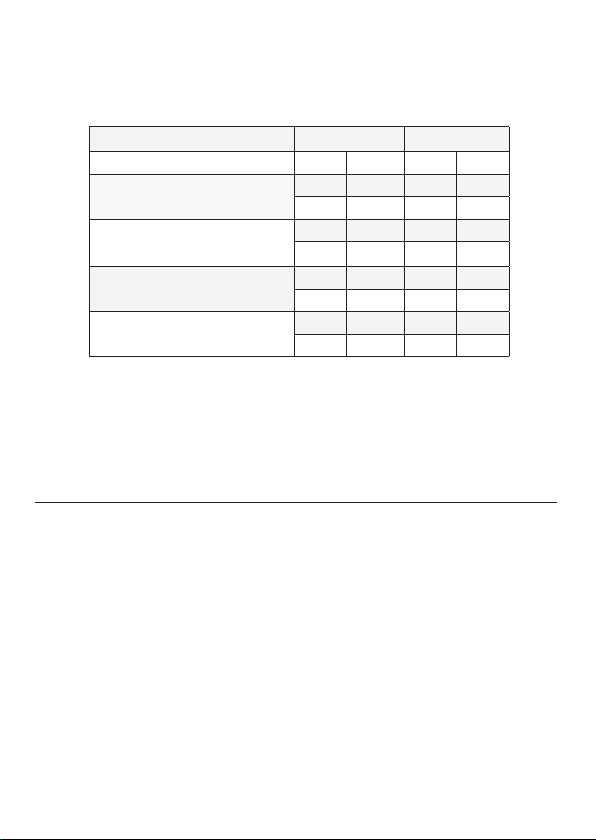
2Cidron Slimline (VG3 QR) Reader -
Technical specications
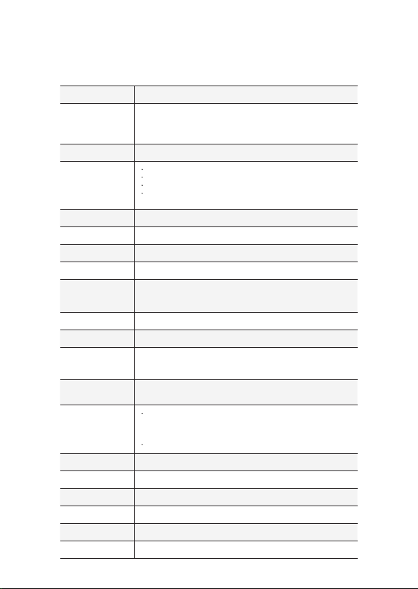
Operating frequency 13,56MHz.
Reading technologies
MIFARE® CSN 4 byte, MIFARE® CSN 7 byte, MIFARE® Classic, MIFARE® Plus
and MIFARE DESFire® EV1. Also supports other ISO 14443 A/B* compatible cards.
*Not all ISO14443 B cards have been implemented in the reader, please contact
Civintec Global for more details on current status.
Mobile ID ISO18092NFC, BLE (Bluetooth low energy)
Barcode/QR scanner
Area image 640 x 480 pixels, Filed of View 68°(H) x 51(V)
Decode range: 20mm-150mm(QR 20MIL)
Roll/Pitch/Yaw: 360°, ±55°, ±55°
Multiple formats supported (1D & 2D Codes): QR Code, Micro QR code,
PDF417, Code 128, Code 39 and most mainstream 1D and 2D barcodes.
Secure Access Module
(SAM) MIFARE SAM AV2, external SIM card connection slot.
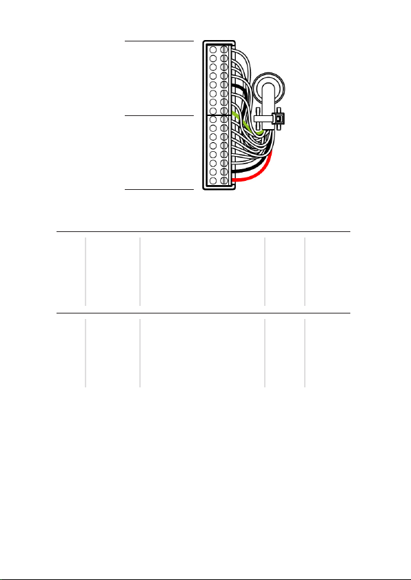
Communication protocols Wiegand, RS485 (OSDP 1, OSDP 2, including Secure channel),BLE.
Reading output format 24-1024 (excluding parity bits)
Keypad output format Wiegand 4bit, Wiegand 8bit (Dorado), Wiegand 26bit, OSDP ASCII format.
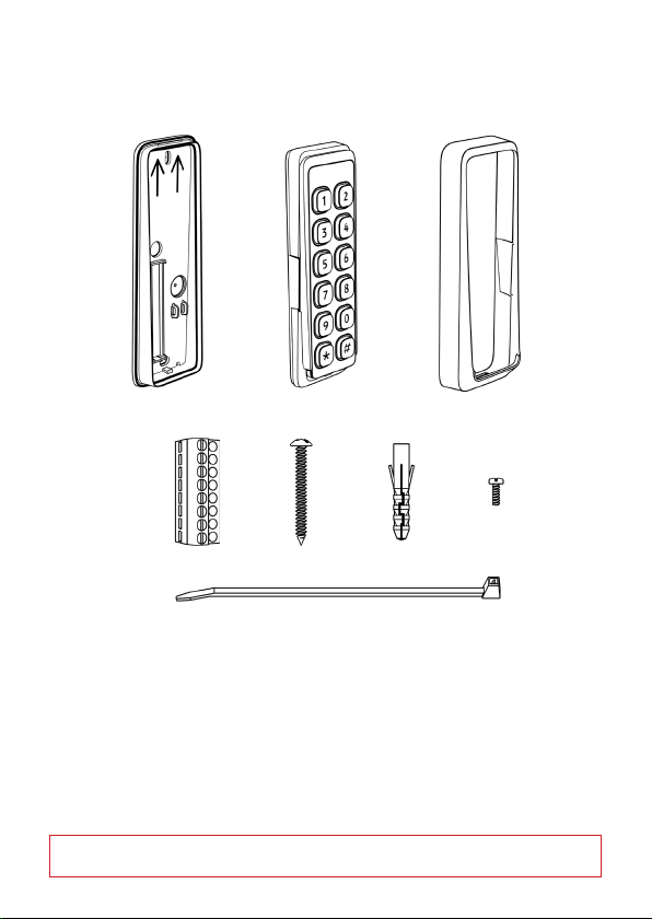
Keypad
12 digit keypad in 4 rows of 3 keys in each row with congurable
backlight in blue color. Control features On/O/Auto indicators.
Light itensity can be adjusted.
Indicators LED, Green, Red and Yellow (Bi-color). Backlight in blue color. Buzzer.
Power supply 9 – 30VDC
Input/Output
4 input for LED and buzzer and 2 congurable General Purpose Input/Output
(GPI/O). The GPI/O’s are push/pull type which provides 5VDC as output when “high”
on each respective GPI/O connection pin.
Tamper alarm Built-in mechanical tamperswitch which allows for
indication both break o protection and opening of the reader.
Operating temperature
RFID reader: -40° ~ +70°C (With thermostat controlled embedded heater)
When installing readers in environments with extreme heat(above + 50°C)
it is recommended to utilize the climate protection SC9901-V which provides
additional shading to the reader.
QR code module: -20°~ +55°C
Heater Thermostat controlled embedded heater.
Operating humidity 0 – 95% RHNC (Relative Humidity No Condensation)
Ingress Protection
Classication IP65 require together with weather protection cover SC9901-T or SC9901-V.
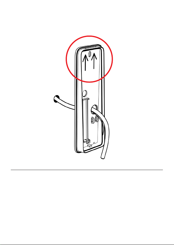
Housing dimension L=180mm, H=95mm, W=63mm
Conguration Methods Conguration card, Congcard software or factory congured readers.
Compliances FCC, CE

3Power Consumption
The above values are excluding heater consumption which is variable and depending on
conguration settings. Default value is 220 mA at 12VDC but can be congured in 20 mA
intervals from minimum 120 mA to maximum 300 mA. When the heater is set in automatic
mode, the heater will be activated when the internal temperature of the reader is below +1°C,
the heater will automatically deactivate when the internal temperature exceeds +5°C.
Depending on the heater consumption setting the time it will take for the reader to exceed +5°C
will vary- a higher power consumption setting will reduce the time required to heat the reader.
Current draw (idle) is dened as reader connected to power, no LED’s lit, buzzer is not
sounding and no reading of credential or key pressing is processed by the reader. Current
draw (peak) is dened as reader powered with both backlight and LED frame lit (Yellow),
buzzer is sounding and reader is reading a credential while simultaneously a key pressing is
processed.
Model Feature Brightness Current draw (idle)
Model: Civintec Global Cidron LED-Bar Backlight 12VDC 24VDC
SC93100-MDEB
STD 13.56MHz/125KHz/2.4GHz with keypad
Low Low 90 mA 47 mA
Medium Low 90 mA 47 mA
SC93110-MDEB
STD 13.56MHz/125KHz/2.4GHz without
keypad
Low Low 90 mA 47 mA
Medium Low 90 mA 47 mA
SC93200-MDB
SLIM 13.56MHz/2.4GHz with keypad
Low Low 34 mA 18 mA
Medium Low 34 mA 18 mA
SC93210-MDB
SLIM 13.56MHz/2.4GHz without keypad
Low Low 34 mA 18 mA
Medium Low 34 mA 18 mA

4
1 x
2 x 2 x 2 x 1 x
• 1pc Installation plate
• 1pc Reader module with front plate
• 1pc Front cover
• 2pcs Terminal connector (8-pin)
• 2pcs Installation screws
• 2pcs Screw plugs
• 1pc Cable strip
• 1pc Fixing screw
• 1pc Quick installation guide
Package content:
* Please note that all pictures in this manual are illustrations and do not represent the actual sizes and form of
the components.

5
3 x 3 x
• 3pcs Installation screws
• 3pcs Screw plugs
• 2pcs Fixing screw
• 1pc Tamper switch bolt
Package content:
* Please note that all pictures in this manual are illustrations and do not represent the actual sizes and form of
the components.
2 x 1 x

6
~20 cm
In order to facilitate installation a cable length of 20cm is recommended.

7
Ensure that the installation plate is xed in the correct direction, i.e. the arrows
pointing upwards.

8
Ensure that the area behind the tamper switch bulb of the installation plate is at,
to be able to push the bulb for correct tamper alarm functionality. If it is not at
enough, you will nd accessories in this manual that will assist with improving
this functionality.

9
Make sure to place the terminal connectors with the fastening screws
facing towards you.
P4 - Blue socket
P5 - Black socket

10
1. Maximum wiegand cable length is 150 meters and requires a high
quality shielded cable with minimum AWG18 dimension (=0.8231mm2) in
an environment free from electrical noise. A cable with smaller dimension
or an installation environment with electrical disturbances will reduce the
maximum cable length.
2. Wiegand & Clock/Data requires dedicated wires for external control of
Green LED, Red LED, Buzzer and Keypad backlight.
3. When utilizing the GPI/O’s, each respective GPI/O1 or GPI/O2 must be
connected to each respective pin and also to GND. The general purpose
input/output will only be activated if so applied in the reader conguration.
4. RS 485/OSDP requires twisted pair cable.
K-LED
BZ
R-LED
G-LED
D-/TX
D0
D1
D+/RX
T/GPIO3
GPIO1
GPIO2
GND
B/RX
A/TX
GND
DC+
P4
Blue
P5
Black
T/GPIO3
GPIO1
GPIO2
GND
B/RX
A/TX
GND
DC+
D+/RX
D1
D0
D-/TX
G-LED
R-LED
BZ
K-LED
Tamper output
General purpose I/O
General purpose I/O
Ground
RS485 -
RS485 +
Power supply
Power supply 9-30 VDC
QR-RX
Wiegand D1/CLK
Wiegand D0/DATA
QR-TX
Green LED control
Red LED control
Buzzer control
External Keypad LED control
DescriptionPIN Wiegand
x
x
x
x
x
x
x
x
x
x
x
x
x
x
x
x
P4 - BlueP5 - Black
RS485/
OSDP
x
x
x
x
x
x
x
x
-
-
-
-
-
-
-
-

11
1.Red wires(DC+),The rst PIN that connects to the terminal block
2.Black wires(GND),The second PIN connects to the terminal block
3.Green wires(RX),The 9 PIN connects to the terminal block
4.White wires(TX),wires(GND),The 12 PIN connects to the terminal block
Matte black, part no: SC9292-SQ
QRcode mode There are four
wires,power and communication
* Screws and screw
plugs included with
accessory.

12
Make sure no excess connection cable is left in between the reader
module and the installation plate.
Use the enclosed cable strip to x the cable in the cord grip. It is
recommended to connect the the wires to the terminal connectors
before tightening the cable strip.

13
1.Red wires(DC+),The rst PIN that connects to the terminal block
2.Black wires(GND),The second PIN connects to the terminal block
3.Green wires(RX),The 9 PIN connects to the terminal block
4.White wires(TX),wires(GND),The 12 PIN connects to the terminal block
Matte black, part no: SC9292-SQ
Install Mounting Plate with
QR CODE MODE
* Screws and screw
plugs included with
accessory.

14
When installing the reader to the mounting plate ensure that
the reader pin header contact perfectly aligns with the terminal
connector block.

15
Mount the front cover as per the image above and make sure it is
tted correctly.
In order to do so, allign and t the top snap fastening, apply and main-
tain pressure on the top of the front cover while sliding the front cover
over the bottom snap fastening.

16
To secure the front cover to the reader use the supplied xing screw
and x it into the installation plate through the front cover.

17
To open the reader, rst remove the xing screw and then detach the
front cover from the installation plate by inserting the tip of the tool
into the slot at the bottom of the front cover and move the tool upwards.
This will release the front cover without damaging the front cover and/
or the installation plate.
Cidron installation tool, part no: SC9914

18 Overview, programming of reader
Resetting the
OSDP secure
channel.
see page: 20
Changing
authentication card
see page: 19
Setting the reader in programming mode
see page: 17
Conguring the
reader
see page: 18

19
In order to set the reader in programming mode, present the valid
“Authentication Card” to the reader as shown. The reader will beep and
start blinking yellow to indicate that it is now in programming mode.
The Reader is in programming mode for 10 seconds. If no other
pro-gramming card is presented within this time, the reader will return
to normal mode. When a reader leaves programming mode it is
indicated by a blinking red LED and a beep.
Note: for above 3.80.04 rmware version, the LED status of authoriza-
tion mode is yellow and green ash alternately.
BEEP !
Setting the reader in
programming mode
Reading distance
approximately 2 cm.

20
1: Set the reader in programming mode, see page: 17
2: Present the “Conguration Card” to the reader as shown. Keep the
card within reading distance until the reader beeps and blinks in green.
The reader is now programmed and ready for use according to the
conguration settings on the conguration card.
Conguring the reader
BEEP !
Reading distance
approximately 2 cm.
This manual suits for next models
3
Table of contents