Clack Valves WS1.5 Supplement

Water Specialist
1.5”, 2” and 2”QC Control Valve
Drawings and Service Manual
HYDROCARBONS SUCH AS KEROSENE, BENZENE, GASOLINE, ETC., MAY DAMAGE
PRODUCTS THAT CONTAIN O-RINGS OR PLASTIC COMPONENTS. EXPOSURE TO
SUCH HYDROCARBONS MAY CAUSE THE PRODUCTS TO LEAK. DO NOT USE THE
PRODUCT(S) CONTAINED IN THIS DOCUMENT ON WATER SUPPLIES THAT CONTAIN
HYDROCARBONS SUCH AS KEROSENE, BENZENE, GASOLINE, ETC.

Page 2 WS1.5", 2" and 2"QC Drawings and Service Manual
WS1.5", 2" and 2"QC Drawings and Service Manual Page 3
Table of Contents
• WS1.5 Generation 2 shown
Pages
Installation Summary 4
General Specifications and Pre-Installation Checklist 5
Valve Port Orientation Diagrams 6-8
Installation Instructions 9-10
System Startup 11
Troubleshooting Procedures 17-20
WS1.5 Control Valve Cycle Positions 21-23
WS2 Control Valve Cycle Positions 23-25
Base Assemblies 30
Injector Graphs 35-39
Motorized Alternating Valve Applications 43-47
No Hard Water Bypass 48-49
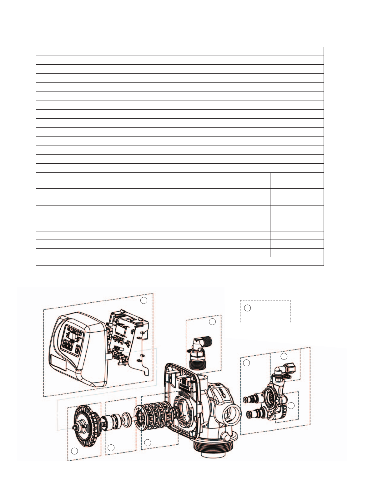
Service Instructions
Service
Step Description Exploded
Views Instructions
1 Front Cover and Drive Assembly * 12
2 Drive Cap Assembly 26-29 13
3 Pistons 26-29 14
4 Spacer Stack Assembly 26-29 14
5,7 Injector Cap, Screen, Injector Plug and Injector 31-33 15
6Refill Flow Control Assembly or Refill Port Plug 34 15
8 Drain Line Flow Control (DLFC) 40-41 16
9 Water Meter (not shown below) 42 42
* See software-specific Programming and Front Cover Manual
1
3
4
7
6
5
8
2
9Not Shown
• Meter

Page 4 WS1.5", 2" and 2"QC Drawings and Service Manual
Installation Summary
Installation Date:___________________________________________
Installation Location: _______________________________________
Installer(s): _______________________________________________
Phone Number: ____________________________________________
Application Type: (Softener)_______ Other:____________________
Water Source: ____________________________________________
Water Test Results:
Hardness:___________ Iron: ___________pH:___________________
Other: ___________________________________________________
_________________________________________________________
Misc:
Service Flow Rates: min._________ max.___________
Tank Size: Diameter _________ Height: ______________
Resin or Media Volume: ___________________________
Resin or Media Type: _____________________________
Capacity: _______________________________________
Salt or Fill Setting per Regeneration: _________________
Brine Tank Size: _________________________________
Control Valve Configuration:
Valve Type: _____________________________________
Valve Part Number:_______________________________
Valve Serial Number: _____________________________
Regenerant Refill Control: _________________ gpm/lpm
Injector Size: ____________________________________
Drain Line Flow Control: __________________ gpm/lpm

WS1.5", 2" and 2"QC Drawings and Service Manual Page 5
Table 1
General Specifications and Pre-Installation Checklist
Minimum/Maximum Operating Pressures 20 psi (138 kPa) -125 psi (862 kPa)
Minimum/Maximum Operating Temperatures 40°F (4°C) - 110°F (43°C)
Power Adapter:
Supply Voltage
Supply Frequency
Output Voltage
Output Current
Refer to Programming and Front Cover Manual
No user serviceable parts are on the PC board, the motor, or the Power adapter. The means of
disconnection from the main power supply is by unplugging the Power adapter from the wall.
Service flow rate
1.5” Valve: 60 gpm (227 lpm, 13.6 m3/h) @ 15 psig (103 kPa) drop
1.5” Gen 2 Valve: 70 gpm (265 lpm, 15.9 m3/h) @ 15 psig (103 kPa) drop
2” Valve standard base: 115 gpm (435 lpm, 26.1 m3/h) @ 15 psig (103kPa) drop
2” Valve quick connect base: 125 gpm (473 lpm, 28.4 m3/h) @ 15 psig (103kPa) drop
Backwash flow rate
1.5” Valve: 50 gpm (189 lpm, 11.4 m3/h) @ 25 psig (172 kPa) drop
1.5” Gen 2 Valve: 52 gpm (192 lpm, 11.8 m3/h) @ 25 psig (172 kPa) drop
2” Valve standard base: 80 gpm (303 lpm, 18.2 m3/h) @ 25 psig (172kPa) drop
2” Valve quick connect base: 85 gpm (322 lpm, 19.3 m3/h) @ 25 psig (172kPa) drop
CV Service
1.5” Valve: 15.5
1.5” Gen 2 Valve: 18.1
2” Valve standard base: 29.7
2” Valve quick connect base: 32.3
CV Backwash
1.5” Valve: 10
1.5” Gen 2 Valve: 10.4
2” Valve standard base: 16.0
2” Valve quick connect base: 17.0
Meter:
Accuracy
Flow Range
± 5%
1.5”: 0.5 – 75 gpm (1.9 – 283 lpm)
2”: 1.5 – 150 gpm (5.7 – 568 lpm)
Regenerant Refill Rate 1.5” Valves: 0.5 gpm (1.9 lpm)
2” Valves: Variable - Shipped from Factory with 2.2 gpm (8.33 lpm)
Injectors 1.5” Valves: See Injector Graphs V3010-15A through 15I
2” Valves: See Injector Graphs V3010-2R-15B through 2G
Inlet / Outlet 1.5” Valves: 1.5” Female NPT or BSPT
2” Valves: 2” Female NPT or BSPT
Drain Line 1.5” Valves: 1.25” Female NPT
2” Valves: 1.5” Female NPT
Distributor Tube Opening
2” Valves with Quick Connect base
All other 1.5” and 2” Valves
Female NPT Inlet & Outlet
2.375” OD (2.0” NPS)
1.90” OD (1.5” NPS)
Female BSPT Inlet & Outlet
63 mm OD
50 mm OD
Tank Connection
2” Valves with Quick Connect base
All other 1.5” and 2” Valves
4”-8UN, 6” Flange, Side Mount
4”-8UN
Shipping Weight
1.5” Valve and Meter: 21 lbs (10 kg)
1.5” Gen 2 Valve and Meter: 23 lbs (11 kg)
2” Valve standard base and Meter: 30 lbs (14 kg)
2” Valve quick connect and Meter: 30 lbs (14 kg)
PC Board Memory Nonvolatile EEPROM
(electrically erasable programmable read only memory)
Compatible with the following typical
concentrations of regenerants/chemicals
Sodium chloride, potassium chloride, potassium
permanganate, sodium bisulfite, chlorine and chloramines

Page 6 WS1.5", 2" and 2"QC Drawings and Service Manual
WS1.5 Gen 2

WS1.5", 2" and 2"QC Drawings and Service Manual Page 7
WS2
Page 8 WS1.5", 2" and 2"QC Drawings and Service Manual
WS2 QC

WS1.5", 2" and 2"QC Drawings and Service Manual Page 9
Installation
GENERAL INSTALLATION & SERVICE WARNINGS
The control valve and fittings are not designed to support the
weight of the system or the plumbing.
Do not use Vaseline, oils, other hydrocarbon lubricants or spray
silicone anywhere. A silicone lubricant may be used on black
o-rings but is not necessary.
HYDROCARBONS SUCH AS KEROSENE, BENZENE,
GASOLINE, ETC., MAY DAMAGE PRODUCTS THAT
CONTAIN O-RINGS OR PLASTIC COMPONENTS. EXPOSURE TO SUCH HYDROCARBONS MAY CAUSE THE
PRODUCTS TO LEAK. DO NOT USE THE PRODUCT(S) CONTAINED IN THIS DOCUMENT ON WATER SUPPLIES
THAT CONTAIN HYDROCARBONS SUCH AS KEROSENE, BENZENE, GASOLINE, ETC.
CLACK WATER METERS SHOULD NOT BE USED AS THE PRIMARY MONITORING DEVICE FOR CRITICAL OR
HEALTH EFFECT APPLICATIONS
Teflon tape is recommended to be used on all threads. Do not use pipe dope, as it may break down the plastics in the control valve.
SITE REQUIREMENTS:
1. The plug in Power Adapter is for dry locations only, and should be connected to an uninterrupted outlet installed within 15 feet
(4.57 meters) of the water conditioner. If the Power Adapter cord has not yet been connected to the control valve, remove the
control valve cover and the drive bracket, and thread the Power Adapter cord through the hole in the back plate. Reinstall the
drive bracket. Weave the cord through the hooks on the right hand side of the drive bracket and connect the end to the four-prong
connector on the printed circuit board. Replace the cover, and plug the Power Adapter into an uninterrupted outlet.
2. The tanks should be on a firm, level surface.
3. All plumbing should be done in accordance with local codes.
4. Do not locate unit where it or its connections (including the drain and overflow lines) will ever be subjected to room temperatures
below 40° F (4° C).
5. INLET/OUTLET PLUMBING: Connect to a supply line downstream of outdoor spigots. Install an inlet shutoff valve and plumb
to the unit’s inlet. Installation of a bypass valve is recommended. If using plastic fittings, ground the water conditioner per local
electrical codes. Do not install any water conditioner with less than 10 feet of piping between its outlet and the inlet of a water
heater. If a water meter is used, install the water meter on the outlet side of the control valve. The turbine assembly may be
oriented in any direction, but is usually oriented pointing up to reduce drainage out of the pipe during service.
6. Locate the water conditioner so the distance between the drain and the water conditioner is as short as possible. All units are
shipped without a drain line flow control washer. Correctly size the drain line and install an appropriately sized drain line flow
control. 1.5” valves are shipped with a ¾” fitting that can be used with the drain line flow controls up to 10 gpm, or an optional
1” fitting can be purchases to be used with drain line flow controls up to 25 gpm. For higher backwash rates, the adapter can be
removed and the 1 ¼” NPT threaded drain outlet can be used. For 2” valves the drain outlet is 1.5” NPT threads. Solder joints
near the drain must be done prior to connecting the drain line flow control fitting. Leave at least 6” (152.4mm) between the drain
line flow control fitting and the solder joints to prevent heat from damaging the flow control. Avoid elevating the drain line above
the control valve where possible. Discharge the drain line through an air gap to a receptacle in accordance with local plumbing
codes.
IMPORTANT: Never insert a drain line directly into a drain, sewer line or trap. Always allow and air gap between the drain line
and the receptacle to prevent back siphonage.
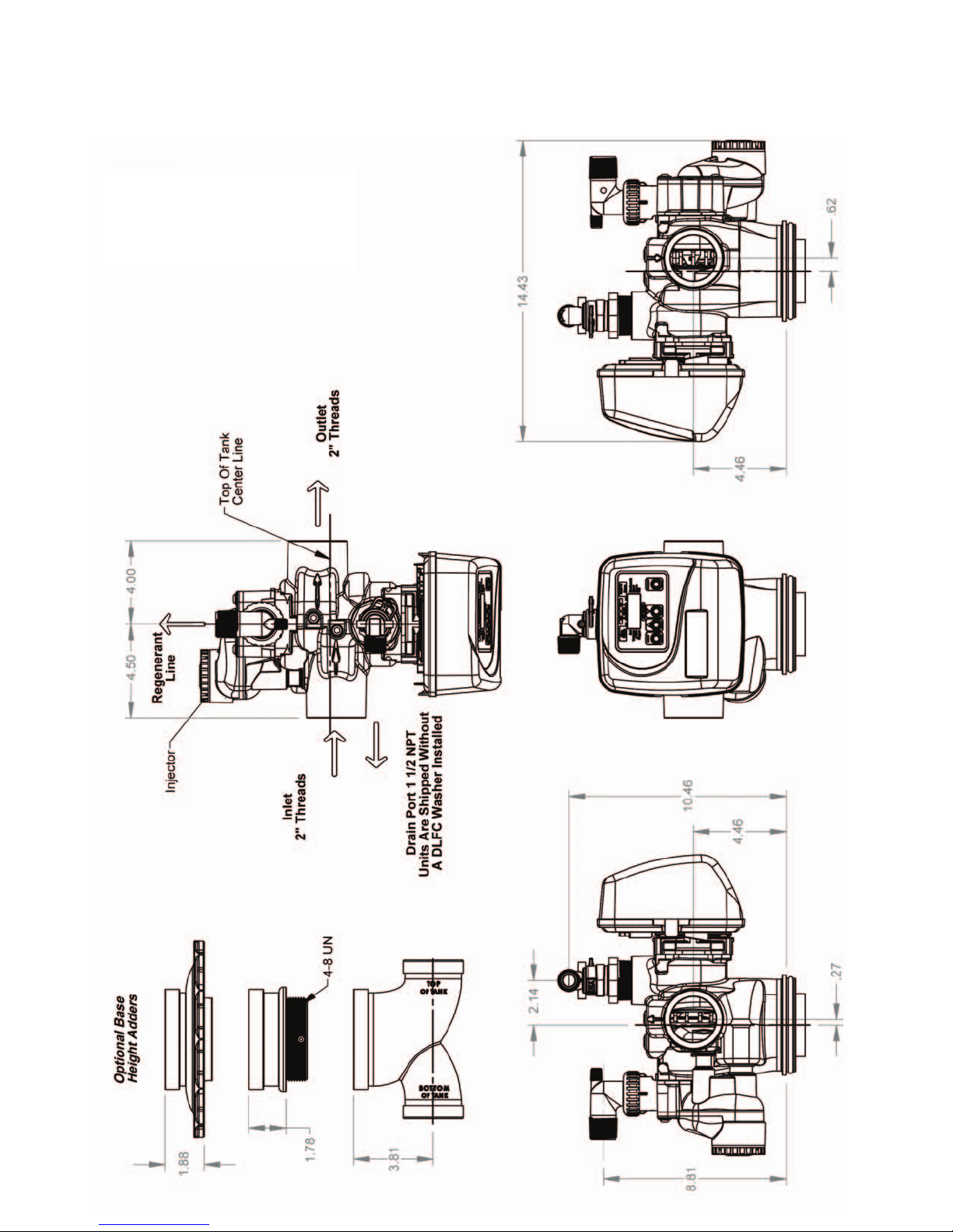
Control Valves A
WS1.5 Flush to -1⁄8”
WS1.5 Gen 2 and WS2 ± 1⁄2”
WS2 QC 2 1⁄4” - 2 1⁄2”
Distributor Tube Pipe Height
for Top Mount WS1.5, WS2 and and WS2 QC control valves
A = Number of inches above the top of the tank for fiberglass tanks.
Please verify distributor pipe and pilot o-ring engagement. Installer
must determine engagement to be able to allow for tank expansion.

Page 10 WS1.5", 2" and 2"QC Drawings and Service Manual
7. Regenerant tanks should be accessible for easy refilling. If the control valve is to be used to regenerate the water conditioner with
brine (saturated salt solution) or other regenerants, use a polyethylene tube to connect the brine valve contained in the regenerant
tank to the regenerant port on the control valve. It is recommended the brine valve contain a safety float. The 1.5” control valve’s
regenerant port has a ½” fitting. Note: ½” tubing that runs longer than 6 feet may restrict draw rates with G and H injectors. A
5/8” fitting is also available.
The 2” control valve regenerant port has a 1” threaded connection. To ensure acceptable operation of the injectors, use 1” pipe to
connect to the brine tank.
An overflow drain line from the regenerant tank that discharges into an acceptable drain is recommended, as a regenerant
overflow could damage furnishings or the building structure. Connect a line to the overflow fitting on the regenerant tank. If an
overflow fitting is not already installed on the regenerant tank, install one. Do not elevate the overflow drain line. Discharge the
overflow drain line through an air gap to a receptacle in accordance with local plumbing codes.
8. Program the control valve: It is very important to program the control valve for the type of system (e.g. water softener or filter.)
Consult your OEM for proper program system settings.
9. The use of resin cleaners in an unvented enclosure is not recommended.

WS1.5", 2" and 2"QC Drawings and Service Manual Page 11
1. After installation is completed, turn on the supply water to check for leaks
2. Fully open a cold water faucet downstream of the system
3. Allow water to run until clear
4. Close the cold water faucet
5. Turn off the supply water
6. The system is now ready for startup
Systems With A Regenerant Tank
1. Manually pour enough water into the regenerant tank to reach the top of the air check valve.
2. Press and hold the REGEN button for three seconds until the drive motor starts. Press the REGEN button to advance the unit to
the backwash cycle. Wait until the motor stops and the backwash time begins to count down.
3. Open the inlet water supply valve very slowly allowing water to fill the tank in order to expel air. CAUTION: If water flows too
rapidly, there will be a loss of media out of the drain.
4. When the water is flowing steadily to the drain without the presence of air, press the REGEN button to advance the control to
brine position. Wait until the motor stops and the brine time begins to count down.
5. Fully open the water supply inlet valve. Check that water is being drawn from the regenerant tank & there should be a slow flow
to the drain. Allow three minutes for the media bed to settle.
6. Press the REGEN button to advance the unit to the rinse position. Allow water to run to drain for 2 - 3 minutes, or until the drain
runs clear.
7. Press the REGEN button to advance to the fill position. Allow water to run into the regenerant tank and prepare it for the next
regeneration. Allow the regenerant tank to fill automatically. Systems with a salt grid should see a water level 1 ½” - 2” above the
grid.
8. Add salt to the tank, and allow ample time to dissolve salt for the brine solution.
9. SANITIZE! Add a sanitizer to the regenerant tank brine well following dosage recommendations specified by the media manu-
facturer. Press and hold the REGEN button for three seconds to begin regeneration. Allow the system to complete the regenera-
tion automatically. The system will now be sanitized and producing treated water. Be sure to check for local codes which may
also specify sanitization methods.
Systems Without A Regenerant Tank
1. Press and hold the REGEN button for three seconds until the drive motor starts. Press the REGEN button to advance the unit to
the backwash cycle. Wait until the motor stops and the backwash time begins to count down.
2. Open the inlet water supply valve very slowly allowing water to fill the tank in order to expel air. CAUTION: If water flows too
rapidly, there will be a loss of media out of the drain.
3. When the water is flowing steadily to the drain without the presence of air, fully open the water supply inlet valve.
4. Press the REGEN button again to advance to the rinse position and allow water to run to drain for 2 - 3 minutes or until the drain
runs clear.
5. Press the REGEN button to advance to the service position.
6. SANITIZE! Add a sanitizer to the media following dosage recommendations specified by the media manufacturer. Be sure to
check for local codes which may also specify sanitization methods.
System Startup

Page 12 WS1.5", 2" and 2"QC Drawings and Service Manual
Service Instructions
1) Drive Assembly
Disassembly and Inspection:
Remove the valve cover to access the drive assembly.
The drive bracket must be removed to access the drive cap assembly and pistons or the drive gear cover. It is not necessary to
remove the PC board from the drive bracket to remove the drive bracket. Disconnect the power source plug (4 pin, black cable)
from the PC board prior to disconnecting any other plugs from the PC board. Disconnect and MAV/ AUX drive motors (2 pin,
black cable) from the PC board. Disconnect the water meter plug (3 pin, grey cable), located on the far right side of the PC board.
Unweave the wires from the side holders. Two tabs on the top of the drive back plate hold the drive bracket in place. Simultaneously
lift the two tabs and gently ease the top of the drive bracket towards your body. The lower edge of the drive bracket has two notches
that rest on the drive back plate. Lift up and outward on the drive bracket to disengage the notches.
To inspect the drive reduction gears, the drive gear cover needs to be removed. The drive gear cover is held in place on the drive
bracket by three clips. The largest of the three clips is always orientated to the bottom of the drive bracket. With the PC board facing
up, push in and down on the large clip on the drive gear cover. Handle the cover and the gears carefully so that the gears do not fall
off of the pegs in the cover. Replace broken or damaged drive gears. Do not lubricate any of the gears. Avoid getting any foreign
matter on the reflective coating because dirt or oils may interfere with pulse counting.
The drive bracket does not need to be removed from the drive plate if the motor needs to be removed. To remove the motor,
disconnect the power and motor plugs from the jacks on the PC board. Move the spring clip loop to the right and hold. Rotate the
motor at least a ¼ turn in either direction before gently pulling on the wire connectors to remove the motor. Pulling directly on the
wires without rotating the motor may break the wires off the motor. Visually inspect the motor for free spinning and remaining brush
life (visible through slots on the size of the motor). Check the pinion gear for endplay. If the pinion gear is pushed tight against the
motor housing, eliminating endplay, slide it away from the housing so the end of the shaft is flush with the end of the gear.
The PC board can be removed separately from the drive bracket but it is not recommended. Do not attempt to remove the display
panel from the PC board. Handle the board by the edges. To remove the PC board from the drive bracket, unplug the power, water
meter and motor plugs from the PC board. Lift the middle latch along the top of the drive bracket while pulling outward on the top
of the PC board. The drive bracket has two plastic pins that fit into the holes on the lower edge of the PC board. Once the PC board
is tilted about 45° from the drive bracket it can be lifted off of these pins. To reinstall the PC board, position the lower edge of the
PC board so that the holes in the PC board line up with the plastic pins. Push the top of the PC board towards the valve until it snaps
under the middle latch, weave the power and water meter wires into the holders and reconnect the motor, water meter and power
plugs.
Reassembly:
If the drive gear cover was removed, reinstall it with the large clip orientated towards the bottom. If all three clips are outside of the
gear shroud on the drive bracket the drive gear cover slips easily into place.
To reinstall the drive bracket, seat the bottom of the drive bracket so the notches are engaged at the bottom of the drive back plate.
Push the top of the drive bracket towards the two latches. The drive bracket may have to be lifted slightly to let the threaded piston
rod pass through the hole in the drive bracket. Maintain a slight engaging force on top of the drive bracket while deflecting the
bracket slightly to the left by pressing on the side of the upper right corner. This helps the drive gears mesh with the drive cap
assembly. The drive bracket is properly seated when it snaps under the latches on the drive back plate. If resistance is felt before
latching, then notches are not fully engaged, the piston rod is not in hole, the wires are jammed between the drive bracket and drive
back plate, or the gear is not engaging the drive cap assembly.

WS1.5", 2" and 2"QC Drawings and Service Manual Page 13
Replace the motor if necessary. Do not lubricate the motor or the gears. To reinstall the motor, move the spring clip loop to the
right and hold. Gently turn the motor while inserting so that the gear on the motor meshes with the gears under the drive gear cover.
Release the spring clip loop and continue to rotate the motor until the motor housing engages the small plastic bulge inside the drive
bracket motor retainer. Reconnect the motor plug to the two-pronged jack on the lower left hand side of the PC board. If the mo-
tor will not easily engage with the drive gear when reinstalling, lift and slightly rotate the motor before reinserting. Reconnect the
power plug.
Replace the valve cover. After completing any valve maintenance, press and hold NEXT and REGEN buttons for 3 seconds or
unplug power source jack (black wire) and plug back in. This resets the electronics and establishes the service piston position. The
display should flash all wording, then flash the software version and then reset the valve to the service position.
2) Drive Cap Assembly
Disassembly 1.5" Valves
Turn off supply water and relieve system pressure. The drive assembly must be removed to access the drive cap assembly. The drive
cap assembly must be removed to access the piston(s). The drive cap assembly is threaded into the control valve body and seals with
an o-ring. To remove the drive cap assembly use the special plastic wrench (V3193-02 Figure 1) or insert a ¼” to ½” flat bladed
screwdriver into one of the slots around the top 2” of the drive cap assembly so it engages the notches molded into the drive back
plate around the top 2” of the piston cavity. See Figure 2. The notches are visible through the holes. Lever the screwdriver so the
drive cap assembly turns counter clockwise. Once loosened unscrew the drive cap assembly by hand and pull straight out.
Disassembly, 2" Valves
After removing the bracket assembly the drive back plate can be removed by squeezing the 2 locking tabs (located at 3 and
9 o-clock around the white gear) and rotating the back plate counter clockwise. The four 1⁄4-20 screws can then be removed and the
drive cap pulled straight back out of the valve. Turning the main gear counter clockwise drives the piston in and may aid in pushing
out the cap.
Inspection
The drive cap assembly contains the drive cap, the main drive gear, drive cap spline, piston rod and various other parts that should
not be dissembled in the field. Visually inspect the drive cap for damage and free operation of the gear and threaded rod. The only
replaceable part on the drive cap assembly is the o-ring.
Figure: 1
Part Number
V3193-02
Figure: 2
Loosens Drive Cap

Page 14 WS1.5", 2" and 2"QC Drawings and Service Manual
3) Main Piston and Regenerant Piston
Disassembly and Inspection
Attached to the drive cap assembly is the main piston and depending on the configuration, a regenerant piston. The regenerant piston
(the small diameter one behind the main piston) is removed from the main piston by unsnapping it from its disassembly latch. To
remove the main down flow piston fully extend the piston rod and then unsnap the main piston from its latch by pressing on the side
with the number. Chemically clean the piston in dilute sodium bisulfite or vinegar, or replace the them. The main piston is teflon
coated. If the teflon coating is abraided, replace the main piston.
Reassembly
Reattach the main piston to the drive cap assembly. Reattach the regenerant piston (if needed) to the main piston. Reinsert the drive
cap assembly and piston into the spacer stack assembly and hand tighten the drive cap assembly. Continue to tighten the drive cap
assembly until the backside of the drive cap bottoms out flush with the casting or the black o-ring on the spacer stack assembly is no
longer visible through the drain port. Excessive force can break the notches molded into the drive back plate. Make certain that the
main drive gear still turns freely. The exact position of the piston is not important as long as the main drive gear turns freely.
Reattach the drive assembly to the control valve and connect all plugs. After completing any valve maintenance, press and hold
NEXT and REGEN buttons for 3 seconds or unplug power source jack (4 pin, black cable) and plug back in. This resets the
electronics and establishes the service piston position. The display should flash all wording, then flash the software version and then
reset the valve to the service position.
4) Spacer Stack Assembly
Disassembly and Inspection
To access the spacer stack assembly remove the drive assembly, drive cap assembly and piston. The spacer stack assembly can then
be pulled straight out. Inspect the black o-rings and inner seals for wear or damage, replace the entire stack if necessary. Do not
disassemble the stack.
The spacer stack assembly may be chemically cleaned (dilute sodium bisulfite or vinegar) or wiped with a soft cloth.
Reassembly
The spacer stack assembly can be pushed into the control valve body bore by hand. The assembly is properly seated when at least
four threads are exposed (approximately 5/8”). Do not force the spacer stack assembly in. The control valve body bore interior can
be lubricated with silicone to allow for easy insertion of the entire stack.
Reattach the drive cap assembly and piston(s) and the drive assembly.
After completing any valve maintenance, press and hold NEXT and REGEN buttons for 3 seconds or unplug the power source jack
(4 pin, black cable) and plug back in. This resets the electronics and establishes the service piston position. The display should flash
all wording, then flash the software version and then reset the valve to the service position.

WS1.5", 2" and 2"QC Drawings and Service Manual Page 15
6) Refill Flow Control Assembly or Refill Port Plug
Disassembly and Inspection
To clean or replace the refill flow control, remove the nut (WS2) or pull out the locking clip (WS1.5 valves) and then pull the fitting
straight out. Remove the flow control retainer. The flow control can be removed by prying upward through the side slots of the
retainer with a small blade flat screwdriver, being careful not to mar the plastic seat.
Chemically clean the flow control or the flow control retainer using dilute sodium bisulfite or vinegar. Do not clean with abrasive
methods. If necessary, replace the flow control, o-ring on the flow control retainer, or the o-ring on the fitting.
Reassembly
Insert the flow control into its seat, confirming correct flow control orientation. Reseat the flow control retainer and reassemble the
fitting (see diagram in the exploded view section).
Do not use Vaseline, oils, or other unacceptable lubricants on o-rings. A silicone lubricant may be used on the o-ring on the elbow or
the retainer, but not on the flow control or its seat.
Refill port plugs should not need to be serviced. O-rings may be replaced if necessary.
5) Injector Cap, Screen, Injector Plug and Injector
Disassembly and Inspection
WS1.5 Gen 1 Body Only
Remove the three bolts from the injector cap and lift off. Remove the screen and clean if fouled.
WS1.5 Gen 2 Body and WS2/WS2QC
The injector can be accessed at the back of the valve by removing the threaded injector cap. The cap is removed by using the
V3193-02 service wrench (figure 1).
Once the cap is removed:
• Gen 2 valve can use the bottom threaded edge of the injector cap at an angle to pry out the injector
• WS2/WS2QC valves can use the open end of the V3193-02 service wrench at and angle to pry out the injector
An injector consists of a throat and nozzle. It can be chemically cleaned with vinegar or dilute sodium bisulfate. The holes can be
blown out by air. Sharp objects, which can score the plastic, should not be used to clean the injector. Scoring the the injector or
increasing the diameter of the injector hole could change the operating parameters of the injector.
If the WS1.5 Gen 2 valve does not use a regenerant the injector plug should not need to be cleaned, just verify that it has both
o-rings on the plug and that it is fully seated.
Reassembly
Press injector into its bore hole and press until seated all the way down. Replace the injector cap.
7) Regenerant Body
For WS1.5 Gen 1 Body, skip to step 8
Disassembly and Inspection
Turn off supply water & relieve system pressure.
The regenerant body would typically only be removed for servicing of the injector screen (not applicable to 2” valves). Removing
the injector cap can allow much of the contained water to drained before removing the body. Remove the (4) ¼-20 screws, the
body can then be pulled straight back off the main body taking care to not lose the o-ring between the regenerant & main body. The
injector screen is installed inside the plastic body behind the injector feed tube. The injector screen can be pushed out from the half
round hole feature behind the injector cap.
Reassembly
Insert the injector feed and draw tubes into the main body, bottoming them out in their bores. Install the injector screen in the 1.5
regenerant body, the small hole in the end of the screen will nest around a feature in the plastic body allowing the large end to be
flush with a step in the tube bore. Confirm the placement of the o-ring on the flange of the plastic body then press the regenerant
body straight onto the main body, assuring the o-rings engages the bore in the main body. Install & tighten the (4)1/4-20 screws. The
lower injector o-ring engages the ID of the injector tube which may push the injector out of position when reinstalling the regenerant
body. Verify the injector is seated all the way down into its bore, then reinstall the injector cap.

Page 16 WS1.5", 2" and 2"QC Drawings and Service Manual
8) Drain Line Flow Control
Disassembly and Inspection
Depending on the flow control installed on the unit, remove the red plastic retaining clip (plastic flow control) or the (4) screws
(stainless steel flow control) to expose the flow control and retainer. The flow controls can be removed by flexing the washer with
a small screwdriver being careful not to mar the plastic seat. The flow control and retainer may be chemically cleaned using dilute
sodium bisulfite or vinegar, do not clean with abrasive methods.
Reassembly
Insert the flow washers back into their respective bores, confirming correct flow control orientation (see diagram in the exploded
view section). Place back into the housing and reassemble the housing /fitting. Do not use Vasoline, oils or other unacceptable
lubricants on o-rings. A silicone lubricant may be used on the o-ring of the elbow or the retainer, but not on the flow control or its
seat.

WS1.5", 2" and 2"QC Drawings and Service Manual Page 17
Table 3
Troubleshooting Procedures
Problem Possible Cause Solution
1. No Display on PC Board
a. No power at electric outlet a. Repair outlet or use working outlet
b. Control valve Power Adapter not plugged into
outlet or power cord end not connected to PC
board connection
b. Plug Power Adapter into outlet or connect
power cord end to PC Board connection
c. Improper power supply c. Verify proper voltage is being delivered to
PC Board
d. Defective Power Adapter d. Replace Power Adapter
e. Defective PC Board e. Replace PC Board
2. PC Board does not display correct time of day
a. Power Adapter plugged into electric outlet
controlled by light switch
a. Use uninterrupted outlet
b. Tripped breaker switch and/or tripped GFI b. Reset breaker switch and/ or GFI switch
c. Power outage c. Reset time of day. If PC Board has battery
back up present the battery may be
depleted. See Front Cover and Drive
Assembly drawing for instructions.
d. Defective PC Board d. Replace PC Board
3. Display does not indicate that water is flowing.
Refer to user instructions for how the display
indicates water is flowing
a. Bypass valve in bypass position a. Turn bypass handles to place bypass in
service position
b. Meter is not connected to meter connection on
PC Board
b. Connect meter to three pin connection
labeled METER on PC Board
c. Restricted/ stalled meter turbine c. Remove meter and check for rotation or
foreign material
d. Meter wire not installed securely into three pin
connector
d. Verify meter cable wires are installed
securely into three pin connector labeled
METER
e. Defective meter e. Replace meter
f. Defective PC Board f. Replace PC Board
4. Control valve regenerates at wrong time of day
a. Power outage a. Reset time of day. If PC Board has battery
back up present the battery may be
depleted. See Front Cover and Drive
Assembly drawing for instructions.
b. Time of day not set correctly b. Reset to correct time of day
c. Time of regeneration set incorrectly c. Reset regeneration time
d. Control valve set at ”on 0” (immediate
regeneration)
d. Check programming setting and reset to
NORMAL (for a delayed regen time)
e. Control valve set at ”NORMAL + on 0” (delayed
and/ or immediate)
e. Check programming setting and reset to
NORMAL (for a delayed regen time)
5. Time of day flashes on and off
a. Power outage a. Reset time of day. If PC Board has battery
back up present the battery may be
depleted. See Front Cover and Drive
Assembly drawing for instructions.
6. Control valve does not regenerate
automatically when the correct button(s) is
depressed and held. For TC valves the buttons are
▲& ▼. For all other valves the button is REGEN
a. Broken drive gear or drive cap assembly a. Replace drive gear or drive cap assembly
b. Broken Piston Rod b. Replace piston rod
c. Defective PC Board c. Defective PC Board
7. Control valve does not regenerate
automatically but does when the correct button(s)
is depressed and held. For TC valves the buttons
are ▲& ▼. For all other valves the button is
REGEN
a. Bypass valve in bypass position a. Turn bypass handles to place bypass in
service position
b. Meter is not connected to meter connection on
PC Board
b. Connect meter to three pin connection
labeled METER on PC Board
c. Restricted/ stalled meter turbine c. Remove meter and check for rotation or
foreign material
d. Incorrect programming d. Check for programming error
e. Meter wire not installed securely into three pin
connector
e. Verify meter cable wires are installed
securely into three pin connector labeled
METER
f. Defective meter f. Replace meter
g. Defective PC Board g. Replace PC Board

Page 18 WS1.5", 2" and 2"QC Drawings and Service Manual
Problem Possible Cause Solution
8. Hard or untreated water is being delivered
a. Bypass valve is open or faulty a. Fully close bypass valve or replace
b. Media is exhausted due to high water usage b. Check program settings or diagnostics for
abnormal water usage
c. Meter not registering c. Remove meter and check for rotation or
foreign material
d. Water quality fluctuation d. Test water and adjust program values
accordingly
e. No regenerant or low level of regenerant in
regenerant tank
e. Add proper regenerant to tank
f. Control fails to draw in regenerant f. Refer to Trouble Shooting Guide number 12
g. Insufficient regenerant level in regenerant tank g. Check refill setting in programming. Check
refill flow control for restrictions or debris
and clean or replace
h. Damaged seal/stack assembly h. Replace seal/stack assembly
i. Control valve body type and piston type mix
matched
i. Verify proper control valve body type and
piston type match
j. Fouled media bed j. Replace media bed
9. Control valve uses too much regenerant
a. Improper refill setting a. Check refill setting
b. Improper program settings b. Check program setting to make sure they are
specific to the water quality and application
needs
c. Control valve regenerates frequently c. Check for leaking fixtures that may be
exhausting capacity or system is undersized
10. Residual regenerant being delivered to service
a. Low water pressure a. Check incoming water pressure – water
pressure must remain at minimum of 25 psi
b. Incorrect injector size b. Replace injector with correct size for the
application
c. Restricted drain line c. Check drain line for restrictions or debris
and clean
11. Excessive water in regenerant tank
a. Improper program settings a. Check refill setting
b. Plugged injector b. Remove injector and clean or replace
c. Drive cap assembly not tightened in properly c. Re-tighten the drive cap assembly
d. Damaged seal/ stack assembly d. Replace seal/ stack
e. Restricted or kinked drain line e. Check drain line for restrictions or debris
and or un-kink drain line
f. Plugged backwash flow controller f. Remove backwash flow controller and clean
or replace
g. Missing refill flow controller g. Replace refill flow controller
12. Control valve fails to draw in regenerant
a. Injector is plugged a. Remove injector and clean or replace
b. Faulty regenerant piston b. Replace regenerant piston
c. Regenerant line connection leak c. Inspect regenerant line for air leak
d. Drain line restriction or debris cause excess back
pressure
d. Inspect drain line and clean to correct
restriction
e. Drain line too long or too high e. Shorten length and or height
f. Low water pressure f. Check incoming water pressure – water
pressure must remain at minimum of 25 psi
13. Water running to drain
a. Power outage during regeneration a. Upon power being restored control will
finish the remaining regeneration time.
Reset time of day.
b. Damaged seal/ stack assembly b. Replace seal/ stack assembly
c. Piston assembly failure c. Replace piston assembly
d. Drive cap assembly not tightened in properly d. Re-tighten the drive cap assembly

WS1.5", 2" and 2"QC Drawings and Service Manual Page 19
Problem Possible Cause Solution
14. E1, Err – 1001, Err – 101 = Control unable to
sense motor movement
a. Motor not inserted full to engage pinion, motor
wires broken or disconnected
a. Disconnect power, make sure motor is
fully engaged, check for broken wires,
make sure two pin connector on motor is
connected to the two pin connection on the
PC Board labeled MOTOR. Press NEXT
and REGEN buttons for 3 seconds to
resynchronize software with piston position
or disconnect power supply from PC Board
for 5 seconds and then reconnect.
b. PC Board not properly snapped into drive
bracket
b. Properly snap PC Board into drive bracket
and then Press NEXT and REGEN buttons
for 3 seconds to resynchronize software
with piston position or disconnect power
supply from PC Board for 5 seconds and
then reconnect.
c. Missing reduction gears c. Replace missing gears
15. E2, Err – 1002, Err – 102 = Control valve
motor ran too short and was unable to find the
next cycle position and stalled
a. Foreign material is lodged in control valve a. Open up control valve and pull out piston
assembly and seal/ stack assembly for
inspection. Press NEXT and REGEN
buttons for 3 seconds to resynchronize
software with piston position or disconnect
power supply from PC Board for 5 seconds
and then reconnect.
b. Mechanical binding b. Check piston and seal/ stack assembly,
check reduction gears, check drive bracket
and main drive gear interface. Press NEXT
and REGEN buttons for 3 seconds to
resynchronize software with piston position
or disconnect power supply from PC Board
for 5 seconds and then reconnect.
c. Main drive gear too tight c. Loosen main drive gear. Press NEXT
and REGEN buttons for 3 seconds to
resynchronize software with piston position
or disconnect power supply from PC Board
for 5 seconds and then reconnect.
d. Improper voltage being delivered to PC Board d. Verify that proper voltage is being supplied.
Press NEXT and REGEN buttons for 3
seconds to resynchronize software with
piston position or disconnect power supply
from PC Board for 5 seconds and then
reconnect.
16. E3, Err – 1003, Err – 103 = Control valve
motor ran too long and was unable to find the
next cycle position
a. Motor failure during a regeneration a. Check motor connections then Press NEXT
and REGEN buttons for 3 seconds to
resynchronize software with piston position
or disconnect power supply from PC Board
for 5 seconds and then reconnect.
b. Foreign matter built up on piston and stack
assemblies creating friction and drag enough to
time out motor
b. Replace piston and stack assemblies. Press
NEXT and REGEN buttons for 3 seconds
to resynchronize software with piston
position or disconnect power supply from
PC Board for 5 seconds and then reconnect.
c. Drive bracket not snapped in properly and out
enough that reduction gears and drive gear do
not interface
c. Snap drive bracket in properly then Press
NEXT and REGEN buttons for 3 seconds
to resynchronize software with piston
position or disconnect power supply from
PC Board for 5 seconds and then reconnect.
17. Err – 1004, Err – 104 = Control valve motor
ran too long and timed out trying to reach home
position
a. Drive bracket not snapped in properly and out
enough that reduction gears and drive gear do
not interface
a. Snap drive bracket in properly then Press
NEXT and REGEN buttons for 3 seconds
to resynchronize software with piston posi-
tion or disconnect power supply from PC
Board for 5 seconds and then reconnect.

Page 20 WS1.5", 2" and 2"QC Drawings and Service Manual
Problem Possible Cause Solution
18. Err -1006, Err – 106,
Err - 116 = MAV/ SEPS/ NHBP/ AUX MAV
valve motor ran too long and unable to find the
proper park position
Motorized Alternating Valve = MAV
Separate Source = SEPS
No Hard Water Bypass = NHBP
Auxiliary MAV = AUX MAV
a. Control valve programmed for ALT A or b,
nHbP, SEPS, or AUX MAV with out having a
MAV or NHBP valve attached to operate that
function
a. Press NEXT and REGEN buttons for 3
seconds to resynchronize software with
piston position or disconnect power supply
from PC Board for 5 seconds and then
reconnect. Then re-program valve to proper
setting.
b. MAV/ NHBP motor wire not connected to PC
Board
b. Connect MAV/ NHBP motor to PC Board
two pin connection labeled DRIVE. Press
NEXT and REGEN buttons for 3 seconds
to resynchronize software with piston
position or disconnect power supply from
PC Board for 5 seconds and then reconnect.
c. MAV/ NHBP motor not fully engaged with
reduction gears
c. Properly insert motor into casing, do not
force into casing Press NEXT and REGEN
buttons for 3 seconds to resynchronize
software with piston position or disconnect
power supply from PC Board for 5 seconds
and then reconnect.
d. Foreign matter built up on piston and stack
assemblies creating friction and drag enough to
time out motor
d. Replace piston and stack assemblies. Press
NEXT and REGEN buttons for 3 seconds
to resynchronize software with piston
position or disconnect power supply from
PC Board for 5 seconds and then reconnect.
19. Err – 1007, Err – 107,
Err - 117 = MAV/ SEPS/ NHBP/ AUX MAV
valve motor ran too short (stalled) while looking
for proper park position
Motorized Alternating Valve = MAV
Separate Source = SEPS
No Hard Water Bypass = NHBP
Auxiliary MAV = AUX MAV
a. Foreign material is lodged in MAV/ NHBP valve a. Open up MAV/ NHBP valve and check
piston and seal/ stack assembly for foreign
material. Press NEXT and REGEN buttons
for 3 seconds to resynchronize software
with piston position or disconnect power
supply from PC Board for 5 seconds and
then reconnect.
b. Mechanical binding b. Check piston and seal/ stack assembly, check
reduction gears, drive gear interface, and
check MAV/ NHBP black drive pinion on
motor for being jammed into motor body.
Press NEXT and REGEN buttons for 3
seconds to resynchronize software with
piston position or disconnect power supply
from PC Board for 5 seconds and then
reconnect.
This manual suits for next models
2
Table of contents
Popular Water System manuals by other brands

Tsunami
Tsunami TSUNAMI-500 Operating and maintenance

Argo-Hytos
Argo-Hytos OPS 010 manual

AmeriWater
AmeriWater 20-3021 Operation manual

Watts
Watts WQC4 RO SERIES Installation, operation and maintenance manual

Pura
Pura QCUF Installation & operation manual

Alpha
Alpha SolarSmart 100 Installation and servicing instructions

Naked
Naked NKD-R Installation & start?up guide

Kärcher
Kärcher WATERCLEAN A 2011201 operating instructions

Water Control
Water Control PS-5 Troubleshooting and maintenance guide

RIDGID
RIDGID RSWS Series Operating instructions and parts manual

AmeriWater
AmeriWater STORAGE TANK Installation & operation manual

ZURN
ZURN Z1325 Assembly manual


