ClairiTech Innovations HumiFresh Hybrid 200 Operating instructions

April 2023 HumiFresh® Hybrid 200 Rev. 1.0 En
Installation & Owner’s Manual
English
READ AND SAVE THESE INSTRUCTIONS
Manufactured by:
ClairiTech Innovations Inc.
1095 Ohio Rd.
Boudreau-Ouest, NB
Canada E4P 6N4

Hybrid 200
1
Table of Contents
1.0. INTRODUCTION................................................................................................................................2
2.0. SERVICE AND WARRANTY ..............................................................................................................3
2.1. FOR CUSTOMER ASSISTANCE .........................................................................................................3
2.2. CONSUMER LIMITED WARRANTY..................................................................................................4
2.3. HYBRID-200 LIMITED WARRANTY:...............................................................................................5
3.0. SPECIFICATIONS ...............................................................................................................................6
4.0. HOW IT WORKS................................................................................................................................7
5.0. INSTALLATION SCENARIOS.............................................................................................................8
6.0. PRE-INSTALLATION .......................................................................................................................12
6.3.1. LOCATE THE UNIT.........................................................................................................................12
6.3.2. PLAN THE DUCTWORK..................................................................................................................13
7.0. INSTALLATION INSTRUCTIONS.....................................................................................................13
7.1. INSTALLING EXTERIOR HOODS &VENTS .................................................................................14
7.2. INSTALLING INTERIOR DUCTWORK &VENTS ..........................................................................15
7.3. MOUNTING THE UNIT...................................................................................................................18
7.4. CONNECTING DUCTS TO UNIT....................................................................................................18
8.0. CONTROL ........................................................................................................................................21
WI-FI INTERNET CONNECTION AND MOBILE APPLICATION..................................................................21
SYSTEM REBOOT ..........................................................................................................................................21
9.0. MAINTENANCE...............................................................................................................................22
10.0. TROUBLESHOOTING ......................................................................................................................22
11.0. RETURN AND EXCHANGE POLICY ..............................................................................................24
Hybrid 200
2
1.0. Introduction
Congratulation on the purchase of your new Hybrid 200. The HumiFresh® Hybrid 200 is a complete
all-season, all-climate ventilation system for your whole home. From basement to bedroom, and
everywhere in between, our only dual-core air exchange system available on the market covers all your
needs. The Hybrid 200 replaces contaminated, humid air with fresh air in every level of your home, in
any climate, without unwanted condensation or the need to defrost. Consequently, no unsightly drains
or annoying defrost schedules to hinder your enjoyment of a comfortable, contaminant-free living
environment.
This Installation and Operation Manual will help you get acquainted with the functions and operation
of your 120 Hybrid, as well as ensure an efficient and hassle-free installation of your new ventilation
system.
This manual shows the suggested installation method. Any structural alterations necessary
for installation must comply with all applicable building, health, and safety
This unit is intended for general ventilation only. Do not use to exhaust hazardous or
explosive material and vapors
Caution
Caution

Hybrid 200
3
2.0. Service and Warranty
2.1. For Customer Assistance
To help in answering questions if you call for service or warranty purposes, please record below the
model and serial number located on the side of the unit.
Product Name:
Model #:
Date of Manufacturing:
Date of Purchase:
Serial #:
Dealer Name (If Any):
Please Note the above
information before
contacting us.
IMPORTANT
To properly validate your warranty, you must complete and return the warranty card within 90 days.
For the Following Inquiries:
-Service
-Parts
-Accessories
-Additional Customer Information
Please contact us by:
Phone: 1-888-533-1348
Email: [email protected]
Website: www.humidex.com

Hybrid 200
4
If your device is not registered, proof of purchase will be required if it requires service after approval from
our Service Department. You can also register your warranty using the Hybrid 200 mobile application.
or online http://www.clairitech.com/support/register.
2.2. Consumer Limited Warranty
ClairiTech Innovations Inc. warrants to the first consumer that this product, when shipped in its
original container, will be free from defective workmanship and materials, and agrees that it will, at its
discretion, either repair the defect or replace the defective Product or part thereof with a new or
remanufactured equivalent at no charge to the purchaser for the period(s) set forth below. The
defective part must be returned to the manufacturer ClairiTech Innovations Inc. All transportation
charges are the sole responsibility of the purchaser.
This warranty does not cover any appearance items of the product nor if the items or product have
been damaged, defaced, subjected to improper voltage, abnormal service or handling, has been altered
or modified in design or construction or was installed and has been rendered inoperable for an
extended period of time.
In order to enforce the rights under this limited warranty, the purchaser must fill out and return the
warranty card within 90 days.
Neither the sales personnel of the seller nor any other person is authorized to make any warranties
other than those described herein, or to extend the duration of any warranties beyond the time period
described herein on behalf of ClairiTech Innovations Inc.
The warranties described herein shall be the sole and exclusive warranties granted by ClairiTech and
shall be the sole and exclusive remedy available to the purchaser. Correction of defects, in the manner
and for the period described herein, shall constitute complete fulfillment of all liabilities and
responsibilities of ClairiTech to the purchaser with respect to the Product, and shall constitute full
satisfaction of all claims, whether based on contract, negligence, and strict liability or otherwise. In no
event shall ClairiTech be liable, or in any way responsible, for any damages or defects in the Product
which were caused by repairs or attempted repairs performed by anyone other than an authorized
servicer, unless approved by ClairiTech in writing. Nor shall ClairiTech be liable or in any way
responsible for any incidental or consequential economic or property damage.
Warranty Period for this product:
Two (2) years on all electrical and electrical
components
Five (5) years on cabinet
10 years ERV core
10 years HRV core

Hybrid 200
5
Additional Items Excluded from
Warranty Coverage (If Any):
Appearance items of the product, Exterior
vent, and any printed material.
Where to obtain service:
From the Manufacturer. (Refer to Page 3)
2.3. Hybrid-200 Limited Warranty:
ClairiTech Innovations Inc. offers a one-year limited functionality warranty for Hybrid-200 system.
Liability Limitation:
ClairiTech Innovations inc. cannot be held responsible for any changes, modifications, or updates
made by third parties (platforms, operators, etc.) which could alter the proper functioning of the
system and the Hybrid 200 application.
This warranty is non-transferable and applies to residential use only.
To obtain supply, accessory, or product information, contact us.
Refer to Page 3 for Contact Information.
Hybrid 200
6
3.0. Specifications
Dimensions
28” W x 23” H x 8” D
Weight
………
Access
Latched and hinged front access to filters and cores
Duct connecting
Six insulating double collars with 6” round connections
Mounting
Mounted from joist
Electrical
25W low / 94W max / 120V @ 60Hz Compatible with 230V 50/60Hz
Filters
Cleanable polyester air filter with easy access
Defrost
Processor controlled balanced frost prevention system
Air Flow
50 to 120 FCM
Capacity
Services up to 3200 square feet
Warranty
Two (2) years on all electrical and electrical components
Five (5) years on cabinet
???? years ERV core
Lifetime HRV core
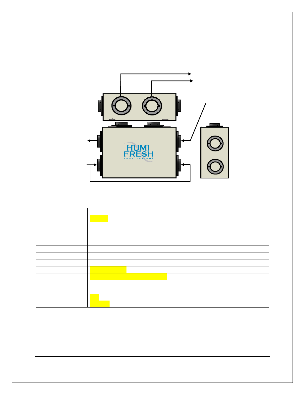
Top
Basement Intake
Outside Exhaust
House Intake
Processed air
from the house
Fresh air
from outside
Side
Front
Hybrid 200
7
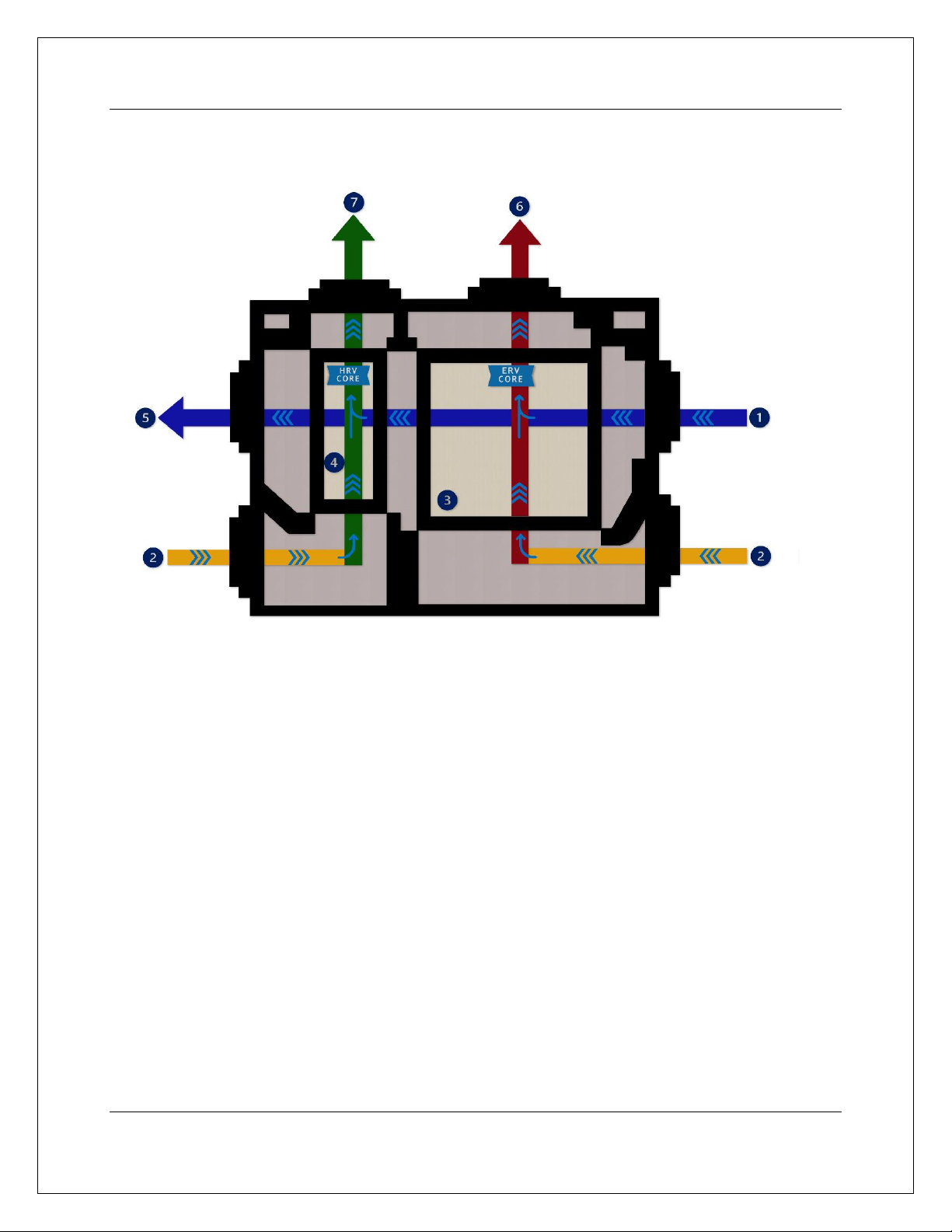
4.0. How It Works
1. Fresh outdoor air enters the unit and flows through the ERV core.
2. Stale air and toxins from upper levels, basement, and crawl spaces enter the unit from the
bottom ports.
3. In the summer, the ERV core transfers the excess humidity and temperature from the
incoming air to the outgoing air. The preferred humidity and temperature level from the inside
environment is then transferred to the incoming fresh air. The process is reserved in winter.
4. The second core, the HRV core, is dedicated completely to the basement. The newly adjusted
humidity level of the fresh air is maintained, but the temperature levels are transferred.
5. The resulting fresh air with temperature and humidity levels similar to the interior environment
is distributed throughout the house.
6. Stale air and toxins are expelled to the outside of the house.
7. The added benefit of the 200 Hybrid circulated air to the basement. This air helps control the
basement’s air quality and virtually eliminates humidity to create a completely livable space.
Hybrid 200
8
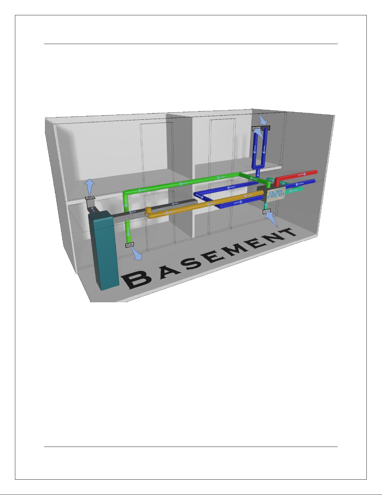
5.0. Installation Scenarios
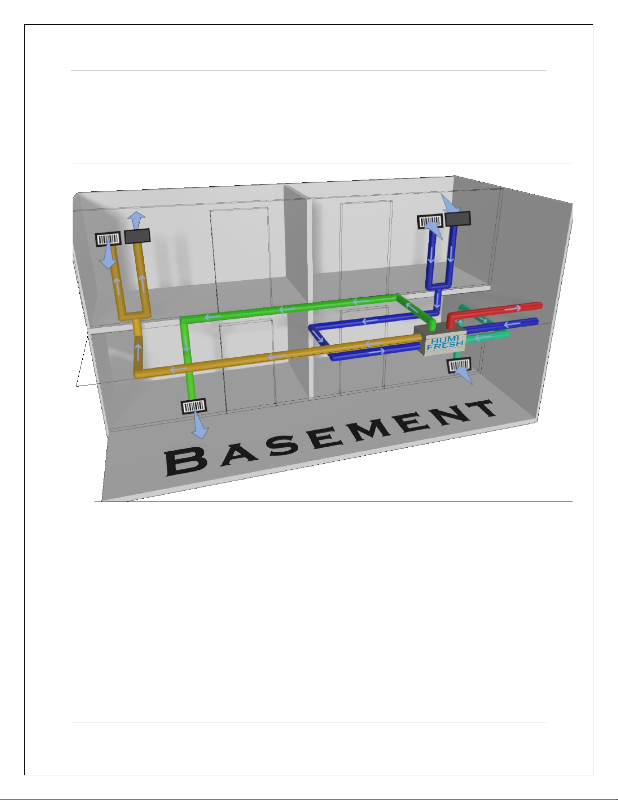
5.1 Fully Ducted System
(For homes without any existing ductwork due to an existing forced-air system)
This installation scenario will require a completely new duct system throughout the entire house.
Stale, humid air is exhausted from the highest humidity areas of the house including the basement,
bathrooms, kitchen, and laundry room. Fresh air taken from outside is filtered and passed through the
ERV and HRV exchange elements where humidity and temperature are exchanged with the stale air
leaving the building. The fresh air is then supplied to the basement, bedrooms, and other principal
living areas to create a comfortable, contaminate-free living environment.
A dedicated air recirculation system for the basement, one of the promising features of the Hybrid
200, will transform the dampest, mustiest basement into a dry, comfortable living area or storage
space. The recirculation system takes fresh, dry air from the upper levels of the house and recirculates
it to the basement before exhausting it back to the outside.
Homes with more than one story require at least one exhaust vent at the highest level of the house.
In the basement, it is recommended to have at least one exhaust vent close to the floor as the humidity
in a basement tends to concentrate near the floor.
Hybrid 200
9
5.2 Pre-existing Ductwork
(For homes with existing ductwork due to an existing forced-air system.)
5.2.1. New Exhaust & Recirculation
This installation scenario will require new ductwork for the exhaust and recirculation systems, and a
tie-in to the existing ductwork of a forced-air system for the fresh air supply.
Stale, humid air is exhausted from the highest humidity areas of the house including the basement,
bathrooms, kitchen, and laundry room. Fresh air taken from outside is filtered and passed through the
ERV and HRV exchange elements where humidity and temperature are exchanged with the stale air
leaving the building. The fresh air is then supplied to the return plenum of the air handler and
distributed to the basement, bedrooms, and other principal living areas via the air handler’s existing
duct system.
A dedicated air recirculation system for the basement, one of the promising features of the Hybrid
200, will transform the dampest, mustiest basement into a dry, comfortable living area or storage
space. The recirculation system takes fresh, dry air from the upper levels of the house and recirculates
it to the basement before exhausting it back to the outside.

Hybrid 200
10
For this kind of installation, it is not obligatory that the forced-air system blower runs
when the unit is in operation. The Hybrid 200 is powerful enough to circulate fresh air to
all rooms of the house without blower assistance.
Homes with more than one story require at least one exhaust vent at the highest level of the house.
In the basement, it is recommended to have at least one exhaust vent close to the floor as the humidity
in a basement tends to concentrate near the floor.
Do not connect the Hybrid 200 unit to any forced-air
system supply duct
5.2.2. New Recirculation only
Regarding this installation scenario, new ductwork for the recirculation system, and a tie-in to the
existing ductwork of a forced-air system for both the stale air exhaust and fresh air supply are required.
Caution

Hybrid 200
11
The air handler's existing duct system removes contaminated, humid air from high humidity areas
such as the basement, bathrooms, kitchen, and laundry room. This air is drawn into the 200 Hybrid's
ERV and HRV exchange units through the air handler's return plenum. Fresh air from outside is also
passed through the ERV and HRV exchange units, exchanging humidity and temperature with the
contaminated air before being expelled from the building. The fresh air is then delivered to the return
plenum of the air handler and distributed to main living spaces like basements, bedrooms, and other
areas through the air handler's existing duct system.
Stale, humid air is exhausted from the highest humidity areas of the house including the basement,
bathrooms, kitchen, and laundry room via the air handler’s existing duct system. The stale air is drawn
through the air handler’s return plenum and into the Hybrid 200’s ERV and HRV cores. At the same
time, the fresh air taken from the outside is filtered and passed through the two cores (ERV and HRV)
where humidity and temperature are exchanged with the stale air leaving the building. The fresh air is
subsequently supplied to the return plenum of the air handler and distributed to the basement,
bedrooms, and other principal living areas via the air handler’s existing duct system.
A dedicated air recirculation system for the basement, one of the promising features of the Hybrid
200, will transform the dampest, mustiest basement into a dry, comfortable living area or storage
space. The recirculation system takes fresh, dry air from the upper levels of the house and recirculates
it to the basement before exhausting it back to the outside.
For this kind of installation, it is obligatory that the forced-air system blower runs in
synchronization with the Hybrid 200 unit.
Homes with more than one story require at least one exhaust vent at the highest level of the house.
In the basement, it is recommended to have at least one exhaust vent close to the floor as the humidity
in a basement tends to concentrate near the floor.
Do not connect the Hybrid 200 unit to any forced-air
system supply duct
Caution

Hybrid 200
12
6.0. Pre-Installation
6.1. Included Components
Before installing your Hybrid 200 system, be sure that you have the right model and accessories. The
following items should be included in the accessory box. If parts are missing, contact our customer
service at US 1-888-533-1348, Can. 1-800-416-9111.
Hybrid 200 unit
1x Owner’s Manual
Cable Ties
1x Warranty Card
Aluminum tape
1x DC Power Supply
…………
4x Chains
…………
1x DC Power Supply
……….
Screws
……….
6.2. Pre-Installation Survey
Before arriving with your full complement of tools and parts ready to start cutting holes and laying
ductwork, it is important to do a pre-installation survey of the residence to determine the appropriate
installation scenario and plan the most effective and efficient layout.
6.3.1. Locate the Unit
•In new construction, the unit should typically be located in the dedicated mechanical or utility
room. These rooms are ideally located in the basement, away from living and sleeping areas
and close to available power sources (and existing ductwork in the case of installation scenario
5.2).
•If a dedicated mechanical or utility room is not present, which is likely the case in most retrofit
situations, you should take the following considerations when determining the best location
to hang the Hybrid 200:
➢Location must allow for easy access to all duct connections, and the unit’s interior filters.
➢It is best to hang the unit close to an exterior wall to keep exterior supply and ventilation
lines as short as possible.
➢Unit should be hung away from any hot surfaces or potential fire hazards.
➢Location must allow for a power source (standard outlet)
➢Consider proximity to existing forced-air blower in the case of installation scenario 5.2.

Hybrid 200
13
6.3.2. Plan the Ductwork
Once the best location for hanging the Hybrid 200 was considered, it is time to begin developing a
plan for your ductwork. You should take the following considerations when developing this plan:
•Duct size - We recommend 8” flex duct connecting to and from the unit, tapered to 6”
ductwork throughout the house for optimal flow and noise reduction. This is a
recommendation only. Please consult the table below for further details on selecting duct sizes.
Duct Size
Flex Duct
Smooth Duct
Fan Rating:
CFM @ 0.25 in.
Wg (L/s @62.5 Pa)
50(25)
80(40)
100(50)
125(65)
50(25)
80(40)
100(50)
125(65)
Diameter in. (mm)
Maximum Duct Length ft. (m)
3(75)
X
X
X
X
5(2)
X
X
X
4(100)
70(27)
3(1)
X
X
105(35)
35(12)
5(2)
X
5(125)
NL
70(27)
35(12)
20(7)
NL
135(45)
85(28)
55(18)
6(150)
NL
NL
125(42)
95(32)
NL
NL
NL
145(48)
7(175) and above
NL
NL
NL
NL
NL
NL
NL
NL
This table assumes no elbows. Deduct 15 feet (5m) of allowable length for each elbow.
NL = No Limit
X = Not Allowed
•Do not install or tie-in to ducts smaller than 4” in diameter as air flow decreases considerably.
•Insulated flex ducts must be used for all exterior connections and are recommended for use
in all bedroom connections for additional noise reduction.
•Keep it simple. Locate exhaust and supply vents in practical but inconspicuous places. Plan
for a minimum of bends and joints. Keep the length of insulated flex ducts to a minimum.
•Exhaust vents should be located in the kitchen, all bathrooms and the basement. Supply vents
should be located in the living room, all bedrooms, and the basement. Be sure to include one
exhaust register on the highest lived-in level of the house in the case of residences with two
or more stories.
•Do not use wall cavities as ducts.
7.0. Installation Instructions
Warning
This manual describes the recommended installation method only. Any structural
alterations necessary for installation must comply with local building, fire, health, and
safety code requirements.

Hybrid 200
14
Before beginning the installation, inspect the unit and the contents of the box for:
•Damage - Inspect both the exterior and interior of the unit for any shipping damage to the
door, latches, hinges, dampers, duct collars, filters, motor assembly, etc.
•Accuracy - Refer to the attached parts list to ensure no parts are missing.
If there is any damage or any parts are missing, please contact your local distributor immediately. All
claims must be made within 30 days of delivery.
7.1. Installing Exterior Hoods & Vents
Now that you know where your unit will be located and how your ductwork will be laid out, you can
begin the actual installation. Start by choosing an appropriate location for installing the exterior hoods
and vents:
•Maximize your distance between the fresh air supply vent and the stale air exhaust vent to
prevent cross-contamination. We recommend a minimum distance of 6 feet (1.8 m) between
vents.
•Both exhaust and supply vents must be installed at a minimum distance of 18 inches (45.7 cm)
from the ground.
•The exhaust vent should not dump stale air into an
enclosed space.
•Make sure the supply vent is at least 6 feet (1.8 m) away
from any of the following:
oDryer exhaust, central vacuum vent, furnace vent,
etc.
oGas meter exhaust, gas barbecue grill.
oGarbage bins and other sources of possible
contamination.
oAny exhaust from a combustion source, etc.
Once you have established an appropriate location for your
exterior vents and hoods, drill the necessary holes and proceed
with the installation.
Additional instructions
•The exhaust and supply vents should be screened against insects and vermin with screening
material no less than ¼” or as per local building codes.
•OPTIONAL: Vents can be covered with suitable hoods to prevent against the entry of rain
or snow; however, this may reduce air flow volume to and from the unit.
•If you are installing vents and corresponding insulated flex ducts through an abrasive surface
such as concrete, use a solid metal thimble to avoid tearing of the flexible material.
•Insulate all exterior openings with appropriate spray foam insulation once flex ducts are
securely in place.

Hybrid 200
15
•Do not secure any ductwork to the unit itself until Section 7.4 - Connecting Ducts to the Unit.
7.2. Installing Interior Ductwork & Vents
Warning
Never install a stale air exhaust vent in a room where a combustion device operates, such
as a gas or oil furnace, a gas water heater, or a fireplace.
7.2.1. Fully Ducted System (See illustration section 5.1)
Exhaust System
Begin by installing vents in areas where contaminants and excessive humidity are produced –kitchen,
bathrooms, basement, laundry rooms, etc.
If the residence has two or more stories, ensure at least one exhaust vent is installed in the highest
level of the house.
Typically, exhaust vents should be installed on an interior wall, 6 to 12 inches from the ceiling.
Steps:
•Measure vent and register, wall grill, or diffuser, and cut hole accordingly.
•Secure vent flanges to wallboard or floorboard using sheet metal screws.
•Attach flex duct to vent collar through the spiral flex wire using sheet metal screws.
•If using insulated flex duct, be sure to pull the insulation back to expose the actual flex duct
before attaching. Do not screw through insulation.
•Secure and seal the connection appropriately.
•Insert the register, wall grill, or diffuser into the top side of the opening.
Supply System
Once your exhaust vents and ductwork are installed, begin installing fresh air supply vents in the
bedrooms and other living areas.
Typically, supply vents should be installed in the ceiling or on an interior wall as close to the ceiling as
possible, with air flow directed towards the ceiling.
In retrofit situations, limited access to the ceiling and/or interior walls may make it necessary to install
a supply vent in the floor. If this is the case, direct the air flow up the wall.

Hybrid 200
16
Steps:
•Repeat connection steps outlined above in Exhaust System installation.
Recirculation System
The basement recirculation system will be the final series of vents and ductwork installed. If your
basement contains multiple rooms, recirculation supply vents can be installed in the largest rooms, or
in each separate room if so desired. In all cases, there should be a minimum of 10 feet between exhaust
and recirculation supply vents.
The recirculation exhaust vent should be ducted to the main level of the house, either with a separate
duct or via the main exhaust system.
Recirculation vents should be installed in the ceiling or on an interior wall as close to the ceiling as
possible, with air flow directed towards the ceiling.
Steps:
•Repeat connection steps outlined above in Exhaust System installation.
7.2.2. Pre-existing Ductwork
7.2.2.1. New Exhaust and Recirculation
(See illustration Section 5.2.1)
Exhaust System
Refer to point 7.2.1 of chapter 7.2 –Fully Ducted System. Considerations and installation are identical.
Supply System
Warning
When performing duct connections to an existing forced-air system, installation must be
done in accordance with all applicable codes and standards. Please refer to your local
building code.

Hybrid 200
17
In the case of a pre-existing forced-air heating or cooling system, the Hybrid 200 will use the existing
ductwork and supply vents to supply fresh air to the bedrooms and living areas. Ensure all supply
vents are at least 10 feet away from all exhaust vents.
Since forced-air configurations vary between suppliers and builders, it is recommended that there be
at least one supply vent on each main living level of the house, as well as in the basement.
Because forced-air blowers operate at much higher CFM rates than the Hybrid 200, a metal T-duct
with a backdraft vent must be installed at the primary connection point to prevent excessive air flow
through the Hybrid 200 when the blower is engaged.
Steps:
•Make sure blower is turned off.
•Measure and cut hole for metal T-duct in the return plenum of the forced-air handler.
•Secure T-duct to return plenum with sheet metal screws. Seal appropriately.
•Attach backdraft vent to one side of T-duct.
•Attach flex duct from the supply vent of the Hybrid 200 to the other
side of the T-duct. Secure through spiral flex wire with sheet metal
screws. Seal appropriately.
Recirculation System
Refer to point 6.2.1 of chapter 6.2 –Fully Ducted System. Considerations and installation are identical.
7.2.2.2. New Recirculation Only
(See illustration Section 5.2.1)
Exhaust System
This scenario will use the forced-air heating or cooling system and ductwork to exhaust contaminated
air from the house through the Hybrid 200.
Since forced-air configurations vary between suppliers and builders, it is recommended that there be
at least one exhaust vent in the basement and on each main living level of the house.
Because forced-air blowers operate at much higher CFM rates than the Hybrid 200, a metal T-duct
with a backdraft vent must be installed at the primary connection point to prevent excessive air flow
through the Hybrid 200 when the blower is engaged.
Steps:
•Make sure blower is turned off.
•Measure and cut hole for metal T-duct in the return plenum of the forced-air handler.

Hybrid 200
18
•Secure T-duct to return plenum with sheet metal screws. Seal appropriately.
•Attach backdraft vent to one side of T-duct.
•Attach flex duct from the supply vent of the 200 Hybrid to the other side
of the T-duct.
•Secure through spiral flex wire with sheet metal screws, seal appropriately.
Supply System
Refer to sub-point 7.2.2.1 of point 7.2.2 –New Exhaust and Recirculation. Considerations and
installation are identical.
Recirculation System
Refer to point 7.2.1 of chapter 7.2 –Fully Ducted System. Considerations and installation are identical.
Caution
In the case of a New Recirculation Only installation, ensure that the forced-air blower
operation is synchronized with the unit operation.
7.3. Mounting the Unit
With all of your vents and ductwork now successfully installed, it is time to mount the Hybrid 200 in
the location you chose in section 6.3:
•Use the 4 chains provided and unit-mounted hooks to
suspend the unit directly from the floor joists overhead. See
illustration at right.
•Make sure the unit is level.
•Make sure the unit’s power cord can reach the nearest
electrical outlet, or make provisions for a new outlet to be
installed near the unit.
7.4. Connecting Ducts to Unit
Your unit is now firmly in place and your ductwork is laid and fully installed. It is now time for the
final step – connecting your carefully planned ductwork to the Hybrid 200. In most installations, you
will use a combination of 8” insulated and non-insulated flexible ducts for these connections. If you
have used 6” ductwork throughout the house, you may want to taper up to 8” ducts when connecting
to the unit for added noise reduction, though it is not necessary.
Hybrid 200
19
Flex Ducts:
•Typically coming from interior supply, exhaust and recirculation lines.
•Before connections are made to the unit itself, a T-duct must be attached to the main exhaust
line, allowing the main exhaust line to be connected to both the exhaust and recirculation ports
of the Hybrid 200. Refer to the identification labels affixed beside each unit’s port.
•Slide exhaust lines over inner collar (6”) or outer collar (8”) of double-collared exhaust and
recirculation ports.
•Secure with sheet metal screws. Seal appropriately.
•Repeat this procedure for the fresh air supply lines, making sure to connect the basement
recirculation line and the upper-level(s) supply line to their corresponding port.
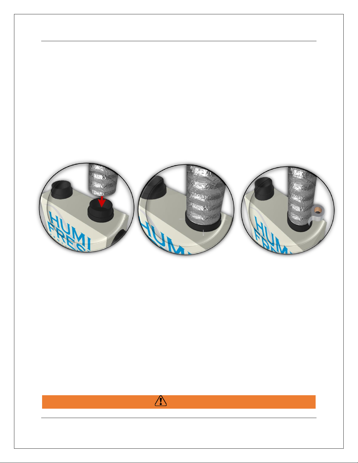
Insulated Flex Ducts:
•Typically coming from exterior supply and exhaust lines, except in instances where additional
noise reduction is required on interior lines.
•Pull back the insulation to expose the flex duct underneath.
•Slide flex duct over inner collar (6”) or outer collar (8”) of double-collared exhaust port.
•Secure with sheet metal screws. Seal appropriately.
•Carefully pull the insulation back over the joint and tuck it between the inner and outer collar
(6”) or over top of the flex duct (8”).
•Pull the vapor barrier back over the insulation and over the outer collar of the double-collared
exhaust port (6”) or over top of the entire assembly (8”).
•Seal joint appropriately. Try to avoid compressing the insulation while sealing, as compressed
insulation loses its R value and may lead to unwanted condensation.
Caution
Table of contents
Other ClairiTech Innovations Fan manuals

Popular Fan manuals by other brands

Argos
Argos Manhattan 432/8317 Assembly instruction

Vents
Vents VCN 100 user manual

Flex-a-Lite
Flex-a-Lite Black Magic 155 installation instructions

ELTA FANS
ELTA FANS Multiflow SMC Series Installation and maintenance instructions

Vento
Vento URAGANO Assembly and installation manual

Fanimation
Fanimation Cancun FP8009OB owner's manual


Thermador
Thermador VTR1400Q, installation instructions

Accura
Accura MINT user manual

Wind Crest
Wind Crest VEN100 installation instructions

Monte Carlo Fan Company
Monte Carlo Fan Company 5hM52XX series owner's manual

Litex
Litex CTM52BNK5C installation guide

Parrot Uncle
Parrot Uncle F8306 Installation & operating instructions