ClairiTech Innovations DVS-BS Instruction Manual
March 2023 Quick Start Installation Guide Rev 2.3 En
Manufactured by:
ClairiTech Innovations Inc.
1095 Ohio Rd.
Boudreau-Ouest, NB
Canada E4P 6N4
1-888-533-1348
Register Warranty at:
https://clairitech.com/en/support/register
For detailed instructions, download the full guide at:
Installation Guides and Manuals - Humidex
Quick Start Installation Guide
English
This Guide Covers the Following Models:
(Basement)
DVS-BS
DVS-BH
DVS-HW
HCS-BS
HCS-BS myHome
(Crawl Space)
DVS-CS
DVS-CH
DVS-CE
HCS-CS
HCS-CS myHome
(BoosterFan)
DVS-CR
HCS-BSF myHome
READ AND SAVE THESE INSTRUCTIONS

Quick Start Installation
1
Introduction
Congratulations on the purchase of your new system which will provide you with year-round
moisture control and improved air quality for a healthy fresh and drier indoor environment. Please
take note the following safety information:
CAUTION For general ventilating use only. Do not use to exhaust hazardous or explosive material
and vapours
WARNING!! To reduce the risk of fire, electric shock, or injury to persons, observe the following:
-Installation work and electrical wiring must be done by qualified person(s) in accordance
with all applicable codes and standards, including fire-rated construction. (APTHC Only)
-When cutting or drilling into wall or ceiling, do not damage electrical wiring and other
hidden utilities.
-Unplug or disconnect the appliance from the power supply before servicing.
a. For permanently connected systems, switch power off at service panel and lock the
service disconnecting means to prevent power from being switched on accidentally.
When the service disconnecting means cannot be locked, securely fasten a prominent
warning device, such as a tag to the service panel.
-Do not use this appliance with any solid-state speed control device.
-Do not operate any fan with a damaged cord or plug. Discard fan or return to an authorized
service facility for examination and/or repair.
-Do not run cord under carpeting. Do not cover cord with throw rugs, runners, or similar
coverings. Do not route cord under furniture or appliances. Arrange cord away from traffic
area and where it will not be tripped over.
Combustion Appliance Present in Dwelling
With the presence of appliances evacuating air outside the building envelope (such as range hood,
bathroom fan, dryer, etc.) there should be an adequate air supply reentering the building envelope
design. If the air pressure inside the building gets lower than the barometric pressure outside air may
be drawn in from any point of entry which may include a chimney. The smoke and gases from any
combustion appliance (oil furnace, gas/wood stove, fireplace, etc.) may be drawn into the building
rather than go out the chimney.
This can be prevented by lowering the maximum ventilation rate of the system or by introducing more
make-up air inside the building. A fresh air kit (Air Supply Ventilator) is available from your dealer, to
introduce additional air supply if needed.
The system’s installation includes allowing for replenishment air coming into the basement
and crawl space either passively via a vent upstairs, open stairwell or with a mechanical
booster fan, thereby avoiding a depressurization in the lower areas.
Quick Start Installation
2
Service and Warranty
Consumer Limited Warranty
ClairiTech Innovations Inc. warrants to the first consumer that this product, when shipped in its
original container, will be free from defective workmanship and materials, and agrees that it will, at its
discretion, either repair the defect or replace the defective Product or part thereof with a new or
remanufactured equivalent at no charge to the purchaser for the period(s) set forth below. The
defective part must be returned to the manufacturer ClairiTech Innovations Inc. All transportation
charges are the sole responsibility of the purchaser.
This warranty does not cover any appearance items of the product nor if the items or product have
been damaged, defaced, subjected to improper voltage, abnormal service or handling, has been altered
or modified in design or construction or was installed and has been rendered inoperable for an
extended period of time.
In order to enforce the rights under this limited warranty, the purchaser must fill out and return the
warranty card within 90 days.
Neither the sales personnel of the seller nor any other person is authorized to make any warranties
other than those described herein, or to extend the duration of any warranties beyond the time period
described herein on behalf of ClairiTech Innovations Inc.
The warranties described herein shall be the sole and exclusive warranties granted by ClairiTech and
shall be the sole and exclusive remedy available to the purchaser. Correction of defects, in the manner
and for the period described herein, shall constitute complete fulfillment of all liabilities and
responsibilities of ClairiTech to the purchaser with respect to the Product, and shall constitute full
satisfaction of all claims, whether based on contract, negligence, and strict liability or otherwise. In no
event shall ClairiTech be liable, or in any way responsible, for any damages or defects in the Product
which were caused by repairs or attempted repairs performed by anyone other than an authorized
servicer, unless approved by ClairiTech in writing. Nor shall ClairiTech be liable or in any way
responsible for any incidental or consequential economic or property damage.
Warranty Period for this product:
Five (5) year on parts and electrical from date of
purchase, two (2) years on all electronic components,
and (2) years on Controller. (HCS Models)
Additional Items Excluded from
Warranty Coverage (If Any):
Appearance items of the product, Exterior vent and any
printed material.
To properly validate your warranty, you must complete and return the warranty card within 90 days.
If your device is not registered, proof of purchase will be required if it requires service after approval
from our Service Department.
You can also register your warranty online http://www.clairitech.com/support/register .
This warranty is non-transferable and applies to residential use only.

Quick Start Installation
3
Pre-Installation
Tools Required for Installation
-Electric reciprocal or hole saw 6¼”
-Drill with a ¼” concrete bit
-Phillips or Robinson Screw Driver
-Measuring Tape
-Hammer
-Pencil
Key Installation Facts
1) Unit must be installed at floor level –up to 3” off the floor.
2) Unit should be installed as far away as possible from the source of replenishment air.
3) Outside duct must be no less than 6” and dedicated for the Unit only.
4) A sufficient replenish air passage must be provided between the location where the unit is
installed and the remaining part of the house or apartment.
5) The area within a radius of 4 feet around the unit should be clear to allow the air to be pulled
into the vents.
6) Unit should not be installed within 8 feet of combustion appliance.
IMPORTANT –What Not to Do
1) DO NOT install the unit more than approx. 3 inches off the floor.
2) DO NOT make more than one turn with the duct and the ductwork should not be longer than 3
feet in total, unless rigid ducting is used - see “Ducting”, Page 4.
3) DO NOT crush the vinyl Pipe.
4) DO NOT install the unit next to a replenishment air supply.
5) DO NOT install the unit within 8 feet of a heat source (Radiator, heater, etc…).
6) DO NOT install in remote closed off areas or where there are obstructions to the airflow.
Ideal location installation locations
For Basement and Crawlspace Models
Air drawn in by system pulls moisture off the surface floors and walls. To maximize the
effectiveness, Install the unit in the dampest, coolest, and lowest part of the basement/crawlspace. If
possible, Install the system as far away as possible from the source of replenishment air.
For BoosterFan Model
The booster fan unit should be installed no further than 20 feet from the system exhaust for optimal
performance. The air exhausted from the booster should also be directed away from the exhaust unit
by using the non-insulated flex provided.
Quick Start Installation
4
Installation
Replenishment air to Basement from Upstairs
The damp air exhausted by the system must be replaced by the warmer/drier air from the upper levels.
If there is no open stairwell, the airflow is restricted from coming down, then install a passive return
grille with 100 sq. inches either in the door, in the wall, or in the floor to allow unobstructed air
downstairs. Alternatively, you can shave down the door leading to the basement by 2”-3”. For the
Crawlspace with Booster Fan, a replenishment grille is provided with the booster fan.
When the flow is limited or inaccessible between rooms downstairs (if there are walls or partitions),
then install a grille 10” x 14” (or other grill configuration, having total area of not less than 100 sq. in.)
in the bottom of the door or wall to avoid having stagnant air in those areas. Otherwise interior doors
must remain open. This insures that all the air drawn into the system comes from all areas of the
basement.
Generally, for improved performance, it is best to keep all exterior basement/crawlspace doors,
windows and vents closed. This will assure that the air is replenished with the air from upstairs and
not with the humid air from outside.
Please check to make sure there are no openings/leaks around windows, doors, vents or other places,
where outside humid air can enter the basement/crawlspace. Make sure that A/C Ducts are properly
sealed and that all A/C Leads to the basement are closed. Sump Pumps holes should be properly
covered.
Selecting the Duct Location
Now that you’ve decided where to install the unit, you must select a location for a 6¼” duct hole in
the outside wall. This hole is needed to pass a duct through the outside wall. Make sure that the hole’s
location is above ground level. Also make sure that the hole doesn’t line up with a stud, electrical
wires, or pipe.
For an interior wall installation: The distance between the system’s back and the exterior wall should
not be more than 12 feet. For this application the flex has to be replaced with rigid piping. Optional:
The bottom cap may be removed for added airflow.
The replenishment air area must have a minimum size of 100 sq.in.

Quick Start Installation
5
Ducting
The basement models come in two sections that allow for flexibility in positioning the duct at the
most convenient height. For both models you can duct from the back of the unit, or from the top of
the unit by removing the top cover. The duct can go through an outside wall, the floor joist or window.
The duct should be vented above ground level to the outside or below ground into a window well that
is open and not sealed off to the outdoors. The outside louver should be high enough to avoid
infiltration of snow, flooding and rodents, etc. All necessary parts and outside louvers are included.
In cases where the basement height clearance is too low, the top portion of the bottom section can
be cut down by a maximum of 40 inches with a cutter, leaving the vents at the bottom intact, for a
minimum unit height of 62 inches. For extra high ceilings, an extension piece of 24 inches is available
which can be added at the top of the unit.
When ducting the unit outside, no more than 3 feet of Vinyl Flex should be used. When circumstances
require a longer span, rigid ducting can be used from the inside of the unit to the wall. The rigid duct
will improve the airflow to compensate for the additional distance the air has to flow to reach the
outside.
When replacing a pane for a window installation, use pressurized wood or similar water/rot proof
material.
Make sure that no pipes, studs or wires are in the way.
The duct has to be dedicated and not combined with any other existing ductwork in operation. Seal
well around the outside opening.

Quick Start Installation
6
Preparing the System for Installation
Now that an installation location has been chosen a hole must be made for the vent. Start by measuring the required
Unit height and mark the location of the hole. Remember that the units cannot be higher than 3” off the ground.
From the inside, drill a pilot hole of approximately ¼” wide
at the center of the proposed 6¼” hole.
Outside the building, find the pilot hole.
Now using a hole-saw, with the pilot hole as a guide, drill a
6¼” hole.
Brick or Concrete Wall: There are two ways of going through brick or concrete. The first method consists of using
a hammer drill. Make holes (approximately 5/8”) with the hammer drill 1” apart through the brick in a circular shape
outlining the 6 ¼” hole. Finish cutting the outer edge of the hole using a chisel. If a hammer drill is not available, a
chisel can be used. As brick is brittle chiseling from the center of the pilot hole will chip the brick easily.
Join the two halves (Bottom section must fit inside Top
section) of the basement model casing together, overlapping
the two pieces such as the desired height is obtained.
Remove screws if necessary. NOTE: If the unit has to be
shorter than 85” cut the top of the bottom part.
Secure the two halves together using ½” metal fastening
screws.
A cover plate can be used to close the gap between both
halves if necessary. Using aluminum tape or duct tape seal
the seam in the back where the two halves join together.
Note: When installing the optional 24” extension, remove top cap and straighten the 90° elbow. Use the 6”
galvanized pipe to extend the length needed. Cut the pipe to the proper length before snapping it together. Attach
the top cap to the extension cover with the 4 screws provided. Add exterior cover to the base and fasten securely
with the provided screws.

Quick Start Installation
7
Fasten the unit to the wall
With the help of a tie wrap attach the flex pipe to the collar on the back of the
unit before attaching the unit to the wall. Insert the other end of the flex pipe
inside the hole in the wall.
(a few Small 9/16” Screw can be used to affix the flex to the mount)
Leaving a 1-inch gap between the top of the unit and the ceiling, drill ¼”
pilot holes through the lips of the unit and the wall.
Insert the four plastics anchors in the wall with the help of a hammer.
Secure the Unit to the wall using the four 1 ¼ inch screws provided.
Attaching the Flex and Outside Vent
Roll the flat metal plate into a cylinder and interlock both ends.
Attach the vent to the newly formed 6” pipe with the ½ inch
screws provided.
From the outside, pull the flex pipe through the 6 ¼” hole onto
the 6” pipe and attach it with a 24” cable tie.
Insert four 2-inch screws to secure the vent to the outside wall.
Make sure the vent is not twisted by inserting the screws too tight
and that the flaps are working properly.
NOTE: If high winds are often present in the location of the vent, they may cause a wind noise inside the house.
If this is the case, an anti-gust hood (AGH-990) is available from your dealer.

Quick Start Installation
8
Installation BoosterFan
1. To minimize noise propagation, install at least 6 ft. of 6 in. insulated flex between the universal
duct boot (connected to the floor register) and the Booster Fan.
2. To further decrease noise propagation, 6 ft. of insulated flex can be used on the exhaust side
of the unit. (Not Included)
3. Flex to pipe the Booster fan away from the exhaust system. Note the airflow arrow directions
4. If the building codes in your area require a backdraft damper to be installed, it must be placed
on the exhaust side of the booster fan to limit the impact on the total airflow through the
unit.
5. This unit is typically sold with an exhaust system. If this is the case, then the Booster Fan
system is made to replace your Replenishment vent required with other exhaust systems.
Typical Installation Diagram
Quick Start Installation
9
Installing and Wiring the Booster Fan
To allow the booster fan to draw air from the upper levels, a universal boot must be installed. First locate a safe place
to cut out a hole to fit the universal boot. Once a safe and adequate area had been found, proceed by cutting the hole.
With the hole cut, install the universal boot which will allow the unit to pull the air down.
Once the boot has been installed, the Booster Fan can be mounted on a floor joist a minimum of 6 ft. away from the
universal boot to reduce noise. Connect the universal boot to the booster fan with the 6 in. insulated flex provided.
If the building codes in your area require a backdraft damper to be installed, it must be placed on the exhaust side of
the Booster Fan to limit the impact on the total airflow through the unit.
Note: A T-junction duct and flex can be added to the exhaust side of the Booster Fan to direct air into all areas of
the crawl space
The Following Wiring is for HCS Booster Fan Only!!!
Now that the booster fan has been installed, it must be connected to the rest of the system. Run the white cable from
the booster to the main exhaust.
Note: These steps must be completed before plugging in the booster fan.
After the white cable has been run it must be connected to the system. Make sure the main exhaust unit is unplugged
before connecting the booster fan.
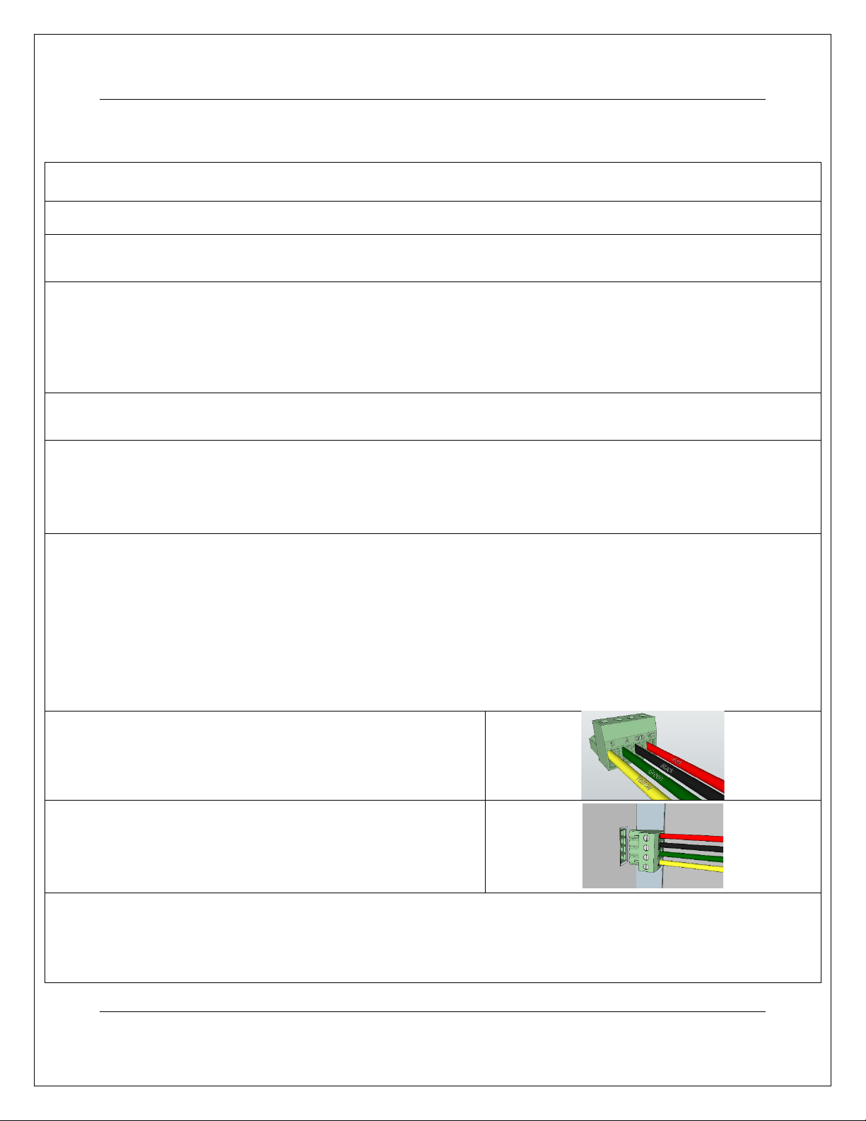
Wiring Guide:
Yellow Wire –B
Green Wire –A
Black Wire –GND
Red Wire –VCC
Note: The main exhaust unit must remain unplugged until the booster fan installation is complete.
On the booster fan’s end of the cable attach the black connector
with the wiring matching the following wiring guide.
Now that the connector has been wired, insert it into the booster
fan unit.
Now that the booster fan has been installed and connected to the main exhaust unit, it can be plugged into any 115V
outlet. Afterwards, the main exhaust unit can be plugged in.
Note: A grounded extension cord with a maximum length of 10 feet may be used if necessary.

Quick Start Installation
10
Return and Exchange Policy
Clairitech Innovations Inc. values its relationship with you and offers you the option to return most
products you purchase directly from Clairitech Innovations Inc., as set forth in detail below.
Policy
Return period of 30 days for unused products and accessories:
Unless you have a separate agreement with Clairitech Innovations Inc., or subject to the provisions
below, all equipment and accessories that have not been used, in new condition and in their original
packaging may be returned to Clairitech Innovations Inc. within 30 days of the date of purchase for
a refund of their purchase price, an equivalent credit note or the exchange of the product, less
shipping and handling charges, resupply fee and applicable taxes, if already paid.
Return period of 15 days for defective or damaged products and accessories:
Requests for refund and/or exchange for defective or damaged merchandise can be made within 15
days of receipt of the merchandise. After 15 days, the manufacturer's warranty applies.
Note: Any product returned to Clairitech Innovations Inc. without the prior permission of Clairitech
Innovations Inc. will be considered an unauthorized return; the customer will not receive any
refunds or credit notes for the product and Clairitech Innovations Inc. will not return the product to
the customer.
Damaged products and accessories:
If you have received damaged items, please contact us by phone or email before destroying or
discarding the product and/or packaging. Failure to comply could see your request denied.
Fees
Unless the product is defective or the return is a direct result of a Clairitech Innovations Inc., the
refund or credit does not include any shipping and handling charges shown on your packing slip or
invoice; you are responsible for those and for any damages incurred during the return shipment.
Procedure
1. Before returning a product, you must first obtain a Return Authorization Number from Clairitech
Innovations Inc. Customer Service before the end of the applicable return period. Proof of purchase
will also be required.
To contact Clairitech Innovations Inc. Customer Service, please call 1-888-533-1348 or Email Us

Quick Start Installation
11
Any product returned to Clairitech Innovations Inc. without the prior approval of Clairitech
Innovations Inc. will be considered an unauthorized return; the customer will not receive any credit
or refund for the product and Clairitech Innovations Inc. will not return the product to the
customer.
2. Pack the product in its original package
3. Insert all the documents received concerning the order to be returned. Remember to keep a copy
of all the documents provided.
4. To obtain a full refund, the products must be returned in perfect condition, in their original
packaging and with all documents, parts and accessories.
5. The return costs must be prepaid; we will not accept deliveries paid at the reception.
6. For your protection, we advise you to provide the shipping service
7. Five days after the date of issue of the return authorization number Clairitech Innovations Inc.
Customer Service, you must send the product to the following address:
ClairiTech Innovations Inc.
1095 ch. Ohio Service Rd
Boudreau Ouest, New Brunswick
E4P 6N4 - Canada
8. Upon receipt of your authorized and compliant return, Clairitech Innovations Inc will issue a
credit or refund equal to the purchase price paid, less shipping and handling charges, restocking
charges and applicable taxes subject to this policy.
9. For assistance please call 1-888-533-1348 or Email Us
10. For any questions regarding warranty terms please call 1-888-533-1348 or Email Us
NO RETURNS ARE POSSIBLE AFTER 30 DAYS FOLLOWING THE DATE OF THE BILLING DATE.
CLAIRITECH INNOVATIONS SHALL NOT BE LIABLE FOR, OR ANY CHARGE OF, A CONSUMER ORDER
ERROR.
This manual suits for next models
11
Table of contents
Other ClairiTech Innovations Fan manuals

Popular Fan manuals by other brands

GÜDE
GÜDE V18-0 Translation of the original instructions

Kichler Lighting
Kichler Lighting Ample instruction manual

Utilitech
Utilitech SFSDE-500B-A manual

Mesko
Mesko MS 7322 user manual

Kichler Lighting
Kichler Lighting Renew Select Patio instruction manual

Zehnder Rittling
Zehnder Rittling ComfoSpot 50 Operating and installation instructions


minkaAire
minkaAire Mr.Ken Crystal instruction manual

Parrot Uncle
Parrot Uncle BBLAB011A manual

minkaAire
minkaAire SUPRA 32 instruction manual

cecotec
cecotec FORCESILENCE 9800 SKYLINE BLADELESS instruction manual

Maico
Maico AS 20 Original Installation Instructions

Hunter
Hunter Type 5 Models Installation and operation manual