CLARCOR UAS SFC Series User manual

Downward Flow Cartridge Dust Collector
l Model - SFC l PATENT NO: 6,902,592
OWNER'S MANUAL

KNOW YOUR EQUIPMENT
READ THIS MANUAL FIRST.
Your SFC system should provide many years of trouble-free service. This manual will
help you understand the operation of your SFC unit. It will also help you understand
how to maintain it in order to achieve top performance. For quick future reference, fill in
the system and filter information in the spaces below. Should you need assistance, call
the United Air Specialists, Inc. customer service number shown below. To expedite your
service, have the following information available when contacting UAS.
UAS ORDER #: ________________________________________________________________
UNIT MODEL #:________________________________________________________________
UNIT SERIAL #:________________________________________________________________
CARTRIDGE FILTER PART #: ____________________________________________________
SYSTEM ACCESSORIES:
______________________________________________________________________________
______________________________________________________________________________
______________________________________________________________________________
INSTALLATION DATE: __________________________________________________________
UNITED AIR SPECIALISTS, INC. CUSTOMER SERVICE
1-800-252-4647

i
TABLE OF CONTENTS
Page
SAFETY PRECAUTIONS ........................................................................................ iii
1. IMPORTANT NOTICE ........................................................................................1
2. INTRODUCTION.................................................................................................1
2.1 Unit Nomenclature ........................................................................................1
2.2 Description and Operation ............................................................................1
2.3 Air Filtering Operation...................................................................................2
2.4 Filter Cleaning Cycle.....................................................................................2
3. INSTALLATION ...................................................................................................3
3.1 Off Loading and Inspection...........................................................................3
3.2 Installation Planning......................................................................................3
3.3 Assembly of Standard Equipment.................................................................3
3.3.1 Hopper Assemblies ..............................................................................3
3.3.2 Fully Assembled Filter Module Sections ..............................................6
3.3.3 Multiple, Bolt-Together Module Sections
(applies to 4 or more modules) ............................................................6
3.4 Electrical Installation ...................................................................................11
3.4.1 Mounting the Controls ........................................................................11
3.4.2 Solenoid Valve Enclosure Wiring ....................................................... 11
3.4.3 Heater Wiring......................................................................................15
3.5 Compressed Air Connection .......................................................................15
3.6 Assembly of Optional Equipment................................................................15
3.6.1 Blower Package Installation ...............................................................15
3.6.2 Duct Silencer Installation....................................................................18
3.6.3 Rotary Air Lock Installation.................................................................18
3.6.4 Abrasive Inlet Installation ...................................................................18
3.6.5 Drum Lid Installation...........................................................................18
3.6.6 Inlet Cover and Blank Cover Plate Installation...................................19
3.6.7 Remote Blower Start/Stop Assembly .................................................19
3.6.8 Explosion Vents..................................................................................21
3.6.9 Extend Dirty Air Plenum (EDAP) for 5 high units...............................21

ii
Page
4. OPERATION .....................................................................................................21
4.1 Start-Up.......................................................................................................21
4.2 Checklist......................................................................................................23
4.3 Checking the Pulse Cleaning System.........................................................23
4.3.1 Digital Pulse Monitor Panel (DPM).....................................................23
4.3.2 Digital Pulse Control Panel (DPC) .....................................................24
5. SERVICE ..........................................................................................................24
5.1 Cartridge Filter Removal and Replacement................................................24
5.2 Dust Removal .............................................................................................24
5.3 Servicing the Compressed Air Components...............................................25
5.4 Servicing the Direct Drive Blower and Motor System.................................25
5.5 Servicing Cartridge Media .........................................................................25
5.6 Servicing Optional Return Air Safety Filters (HEPA/ASHRAE)...................25
5.7 ProTura®Nanofiber Cartridge Filters ..........................................................26
5.8 Explosion Vent Replacement ......................................................................26
5.8.1 Dome Style Explosion Vent Replacement .........................................26
5.8.2 Swing Door Re-Arming Instruction.....................................................27
6. TROUBLESHOOTING GUIDE..........................................................................27
7. ILLUSTRATED PARTS .....................................................................................30
SFC Series Bill of Materials ..............................................................................31
WELD FUME COLLECTOR” to read “DOWNWARD FLOW CARTRIDGE DUST COLLECTOR”.

IMPORTANT SAFETY INSTRUCTIONS
To reduce the risk of fire, electric shock, or injury when using your air cleaner, follow these basic precautions:
iii
SAFETY PRECAUTIONS
We have provided many important safety messages in this manual and on your SFC dust collector. Always read and obey
all safety messages.
• Wear protective clothing and safety glasses when handling
collection filters or servicing the dust collector.
• Use proper lifting and rigging equipment to install your dust
collector.
• The dust collector must be properly grounded.
• Disconnect power before servicing.
• Replace all access panels before operating.
• Electrical connections should only be made by qualified
personnel, and be in accordance with local and national
codes and regulations.
• Do not use in explosive atmospheres unless the dust
collector is equipped with the appropriate accessories.
• Keep flammable materials and vapors, such as gasoline,
away from dust collector.
• The unit should be inspected frequently and dirt removed
to prevent excessive accumulation which may result in
flash-over or fire damage.
• The SFC system should not be used to support personnel
or material.
• Operate only in a safe and serviceable condition.
• Do not allow any individual to put lit cigarettes or any
burning objects into any hood which is ducted into the
dust control system.
!
!DANGER
!WARNING
!WARNING
!CAUTION
CAUTION
This is the safety alert symbol.
This symbol alerts you to potential hazards that can kill or hurt you and others. All safety messages will follow the
safety alert symbol and the word “DANGER” “WARNING” or “CAUTION”. These words mean:
Indicates a hazardous situation which, if not avoided, will result in death or
serious injury.
Indicates a potentially hazardous situation which, if not avoided, could result
in death or serious injury.
Indicates a potentially hazardous situation which, if not avoided, may result
in minor or moderate injury.
CAUTION used without the safety alert symbol indicates a potentially
hazardous situation which, if not avoided, may result in property damage.

1
Revised 04/15 SFC
Cartridge Dust Collector
1. IMPORTANT NOTICE
This manual contains important safety information
and precautionary measures. It is impossible to
list all potential hazards associated with every
dust collection system in each application. Proper
use of the equipment should be discussed with
United Air Specialists, Inc. (UAS) or your local UAS
representative. Operating personnel should be aware
of, and adhere to, the most stringent safety procedures.
EXPLOSION HAZARD
• Avoid mixing combustible materials such as aluminum,
paper, wood or other organic dusts with dusts
generated from grinding materials. A fire hazard could
develop from sparks entering the dust collector. When
collecting flammable or explosive materials, the dust
collector should be located outdoors and incorporate
the appropriate safety measures and/or accessories.
• When collecting emissions from spark-producing
processes, care must be taken to reduce any potential
fire hazards. System design should
include methods to prevent sparks from entering
the dust collector. Dust collectors do not contain
fire extinguishing equipment unless specifically
ordered. Experts in the field of fire extinguishing
equipment should be consulted for recommendations
concerning proper fire detection and suppression
systems.
• Some dust collection systems require explosion
venting. Consult your insurance underwriter,
NFPA (National Fire Protection Association) manual
and your local fire authorities to determine the
requirements for explosion venting.
• Be careful and conscientious – consult national
and local fire codes, waste disposal, safety and
other appropriate authorities. Comply with their
recommendations for the proper installation and
operation of dust collection equipment.
• Your dust collector was selected for a particular
application. Consult UAS prior to making any
application or system changes.
• All explosion vent installations should be located to
allow full-unrestricted discharge when system pressure
exceeds the set pressure of the explosion vent. An
explosion vent should never be located where the
discharge from the vent will impact people or plant
equipment.
• Do not use the explosion vent as temporary work
surface for hand tools; i.e., wrenches, screw drivers,
etc. Such actions can cause premature failure to occur
via over stressing the explosion vent.
• All dust collectors handling hazardous or fire/
explosion risk dust, as determined by the user, are
recommended to be located outside the building in
non-traffic areas even though the dust collector is
equipped with an explosion vent.
2. INTRODUCTION
Thank you for selecting UAS dust collection equipment
to assist you in your commitment to a clean and safe
environment. We trust that in purchasing our product,
you have recognized our commitment to continually
offer air cleaning equipment engineered to each dust
collection need and manufactured to the highest
standards. If at any time you have a question about
dust collection, please do not hesitate to call your local
UAS representative.
The SFC is designed to collect process generated
dusts. The optimized pulse cleaning system coupled
with the QuickSeal filter access doors provide the most
dependable and maintenance friendly cartridge collector
in the market.
The SFC dust collector should not be used for any
purpose not listed in this manual.
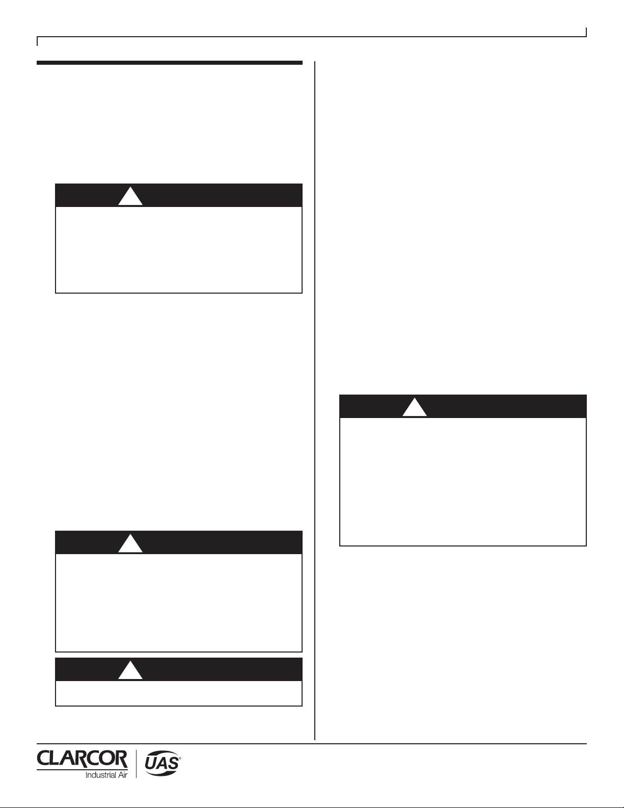
As you review this manual, refer to Figure 1 for
assistance in identifying dust collector parts. The SFC
Specification Table in Section 3 provides additional unit
information.
2.1 UNIT NOMENCLATURE
Example: SFC8-2-H55
SFC = Model collector
8 = number of cartridge filters
2 = number of filter tiers
H55 = unit base arrangement
H55 - hopper with 44” (112 cm) clearance for
standard 55 gallon (208 liter) drum
SD - hopper with 28” (66 cm) clearance for
UAS-supplied 20 gallon (76 liter) drum
OB - open bottom construction
BV - custom bin vent unit with open bottom
DD - dust drawer
2.2 DESCRIPTION AND OPERATION
The SFC is a high-efficiency cartridge dust collector
designed to eliminate airborne dust as it is generated.
Contaminants are captured at the source(s), then
conveyed through ducting to the cartridge filter section
(dirty air section) where the dust is collected. Clean air
is then discharged from the unit through the clean air
discharge.
The dust collector is designed for on-line or downtime
cartridge filter cleaning by means of a customer-supplied
compressed air system.
The SFC is a high-efficiency, horizontally-oriented
cartridge dust collector equipped with 9.48” I.D. and
13.87” O.D. cartridge filters. The larger diameter
ProTura®Nanofiber cartridge filter design allows for
lower pressure losses through the dust collector while
increasing the amount of media contained in each
filter. SFC Series dust collectors have pre-engineered
backward-inclined or radial-type optional blower
packages in 2, 3, 5, 7-1/2, 10, 15, 20, 25 and 30 hp (1.5,
2.2, 3.7, 5.5, 7.5, 11, 15, 18.8, 22.6 kW) assemblies.
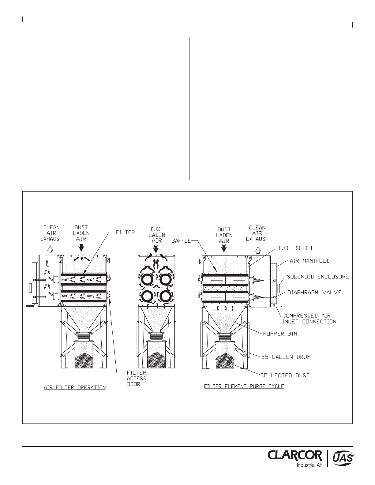
There are two primary modes of operation — the air
filtering operation and filter cleaning cycle. Both modes
of operation are shown in Figure 1.
!DANGER
2
Revised 04/15 SFC
Cartridge Dust Collector
2.3 AIR FILTERING OPERATION
The contaminated airstream is drawn into the dust
collector where its velocity is reduced by inlet baffle
plates to provide even air distribution across the
entire surface area of the cartridge filters. This design
enhances filtration efficiency by establishing a uniform
“dust cake” on the filters. The airstream is then directed
around the cartridge filters and down toward the hopper,
where the heavier particles discharge to the dust
storage drum.
The contaminated air then passes through the
cartridge filters. The filter media strips the dust from the
airstream, allowing only clean air to pass through the
cartridge filter. The air then passes into the clean air
plenum, through a blower package and is discharged
from the unit.
2.4 FILTER CLEANING CYCLE
During normal operation, the surface of the cartridge
filters become loaded with contaminants. The reverse-
pulse cleaning mechanism provides brief bursts of
compressed air, directed through the diaphragm valves,
toward the cartridge filter. This pulsing action dislodges
the collected particles from the media, where they fall
into the hopper and are discharged to a dust storage
drum or drawer.
During the cleaning cycle, each pair of cartridge filters
is cleaned individually. The solid-state sequential
timer actuates a solenoid valve, which allows an
air diaphragm valve to open for approximately 100
milliseconds. High-pressure air from the air manifold
reservoir is directed through the diaphragm valve
toward the venturi mounted on the tubesheet in front
of the cartridge filters. The venturi, in conjunction with
the DIF nozzle, maximizes the compressed air energy
to maximize the amount of collected dust released from
the filter surface.
The dislodged dust removed from the filter is swept
downward into the hopper. The remaining filters are
cleaned sequentially. The sequencing is factory preset
at 10-second intervals and is adjustable to adapt to your
particular cleaning needs.
FIGURE 1
SFC Air Filter Operation & Cleaning
44-10334-0001
3
Revised 04/15 SFC
Cartridge Dust Collector
options are also possible. Structural calculations for
the foundation or other mounting arrangements must
include the weight of the collected material and the
weight of all auxiliary equipment installed with the
dust collector (ducting, abrasive inlet, blower package,
afterfilter assembly, etc.). These weights must be
considered together with wind loading, seismic
loading and other live load ratings when designing the
dust collector foundation support structure. Consult a
professional engineer when designing the foundation
for the unit.
The system should be designed with the ability to
regulate airflow. Two common ways to do this are
through the use of flow/volume control dampers or
variable frequency drives to control the speed of the
fan motor. UAS offers both of these options. If flow
control dampers are selected, the interconnecting
duct work should be designed to account for the
installation of said damper. These dampers can be
installed on the inlet or outlet ducting of the SFC unit.
Whether you control the flow through the use of
a damper or VFD, the ductwork must be properly
sized to meet the recommended air velocities for the
material being collected.
Follow ducting design methods as listed in the
Industrial Ventilation Manual as recommended by
the American Conference of Governmental
Industrial Hygienists.
3.3 ASSEMBLY OF STANDARD EQUIPMENT
CRUSH AND ELECTROCUTION HAZARD
Use adequate safety measures when lifting and
assembling any heavy components. Consult your
plant safety personnel for recommendations.
In preparing to attach the filter module to the
hopper, connect lifting slings and spreader bars
to all filter module lifting lugs with clevis pins. Use
spreader bars to distribute the load evenly.
Location must be clear of all obstructions, such as
utility lines or roof overhangs.
Remove all crating, strapping and hold-down bolts.
Locate all hardware bags, sealant and other assembly
materials provided with your unit.
3.3.1 HOPPER ASSEMBLIES
The SFC Series filter module is designed to mount directly
on top of the hopper assembly. A hopper assembly
consists of a hopper bin, legs, side diagonal sway braces,
rear diagonal sway braces and the hardware installation
kit. Hopper assemblies will be shipped in pieces and will
need to be assembled at the site.
The hopper sections are shipped in pieces for field
assembly. Position the legs as shown in Figure 4 for
single module hopper assembly, or Figure 5 for multi-
modular hopper assemblies.
3. INSTALLATION
3.1 OFF LOADING AND INSPECTION
SFC dust collector modules are shipped assembled
(with cartridges installed) on skid(s). Other skids will
contain the hopper/leg assembly and other components.
Other accessories (afterfilter assemblies, blower
packages, dust storage drums, silencers, etc.)
may be on additional, separate skids.
TIP OVER HAZARD
Lift the dust collector components by the packing skids
or use the external lifting lugs provided on the filter
module. Do not lift the filter module of the dust collector
by placing lift truck forks through the cartridge filter
access doors. The filter support rails or venturi installed
on the tubesheet could be damaged.
Upon receipt of your unit, check for any shipping damage.
A damaged carton indicates that the equipment may
have received rough handling during shipping that may
have caused possible internal damage. Notify your
delivery carrier and enter a claim if any damage is found.
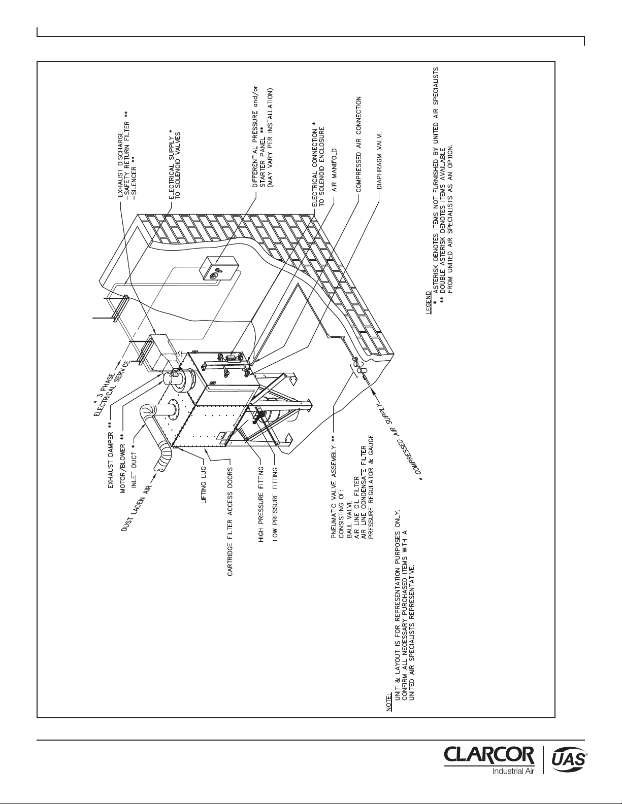
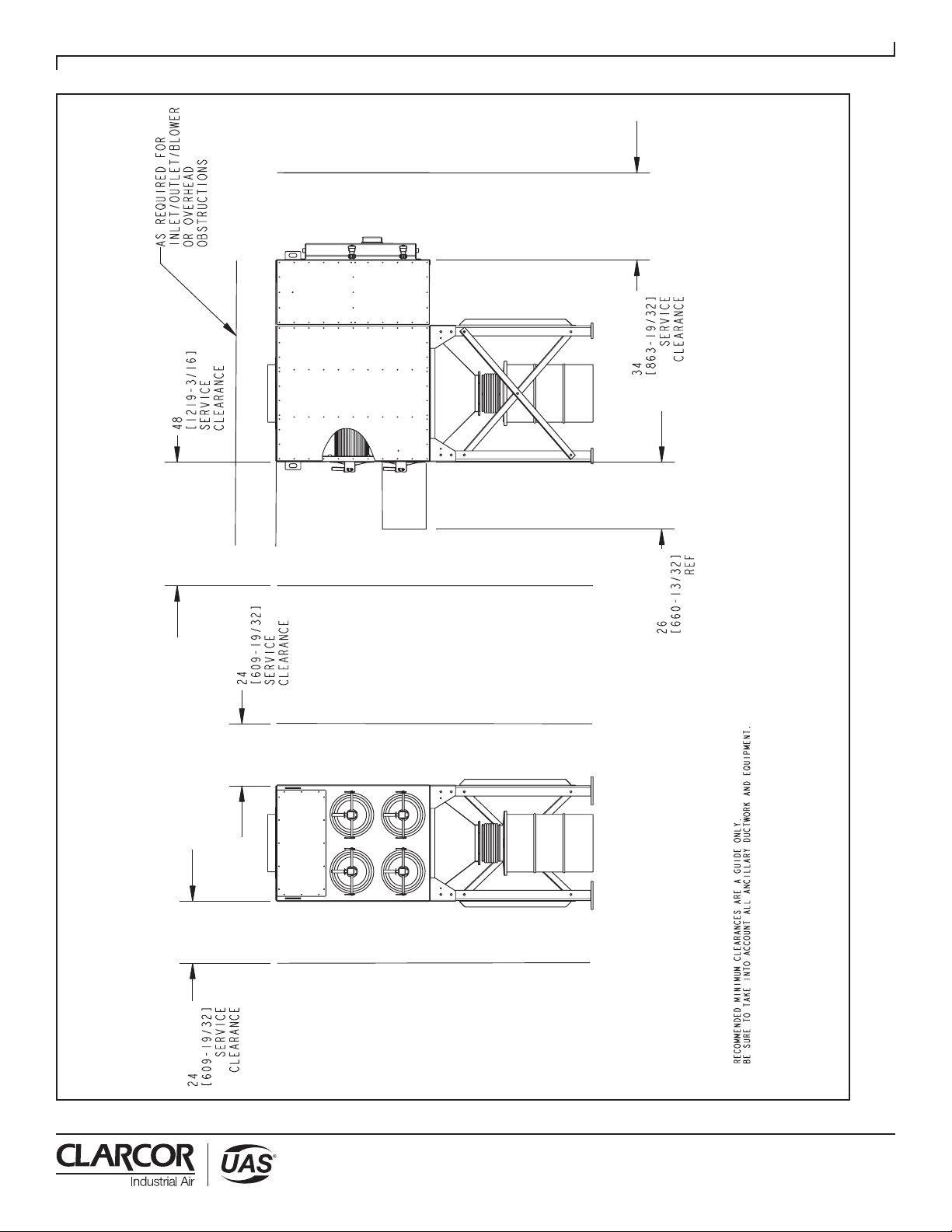
3.2 INSTALLATION PLANNING
The proper location of your dust collection equipment
is very important. Refer to Figures 2 and 3 for typical
installation details.
Certain items should be considered when locating the
unit, such as emptying of the dust storage drum(s), filter
removal requirements, compressed air connections,
access to the clean air plenum, electrical connections,
blower location and discharge direction. The shortest
duct length with a minimum number of elbows will
maximize the performance of the unit. Ease of
maintenance should also be considered when selecting
the location and orientation of the system. Refer to
Figure 3 for recommended clearances.
EXPLOSION HAZARD
In the case of spark producing processes, system
design should incorporate measures to prevent live
sparks from entering the dust collector. Consult local
authorities for the location of the unit and any additional
precautions to consider when collecting combustible,
explosive or hazardous dusts. General warnings and
cautions are provided on page iii and in Section 1.
TIP OVER HAZARD
The SFC dust collector should be mounted on a solid,
level, reinforced concrete foundation. Other mounting
!DANGER
!DANGER
!DANGER
!DANGER
4
Revised 04/15 SFC
Cartridge Dust Collector
FIGURE 2
SFC Typical SINGLE UNIT Installation Diagram
44-10335-0001
5
Revised 04/15 SFC
Cartridge Dust Collector
FIGURE 3
Recommended Unit Clearances
44-10337-0001

6
Revised 04/15 SFC
Cartridge Dust Collector
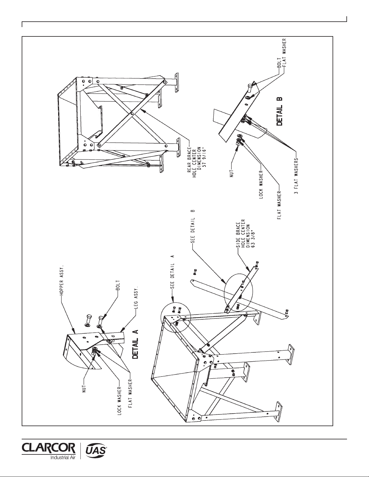
3.3.1.1 SINGLE MODULE HOPPER
ASSEMBLY
Assemble four leg weldments to hopper (refer to Figure
4, Detail A), making sure base pads are oriented as
illustrated. After four legs have been bolted to the
support hopper, locate the four support braces which
measure 60-11/16” between hole centers, and attach to
left and right side of hopper legs as shown in Figure 4.
Locate the two support braces, which measure 55-1/16”
between hole centers. These braces are to be attached
to back legs as illustrated in Figure 4.
After all support braces have been installed. Bolt brace
together as illustrated in Fig. 4, Detail B.
Secure hopper/leg assembly to concrete mounting
pad with appropriate mounting hardware. Anchors
should be provided by customer or contractor
according to local codes.
3.3.1.2 MULTIPLE MODULAR HOPPER
ASSEMBLIES
Position multiple hoppers side by side and bolt through
corner gussets as illustrated in Figure 5, Detail D. After
hoppers have been securely fastened, refer to Figure 6 to
locate your hopper configuration. Using this configuration
and Figure 5, Detail E, locate and attach the leg
weldments to the hopper assembly. Locate the diagonal
support brace which measures 60-11/16” and attach it to
the hopper corner brackets on left and right side of hopper
referencing Figure 5 hopper configuration and Figure 6,
making sure the base pads are oriented as illustrated
in Figure 6. Locate the support braces, which measure
55-1/16” between hole centers. These braces are to be
attached to the back legs as illustrated in Figure 5,
Details A and C.
After all support braces have been installed, bolt side
braces together where they cross as illustrated in
Figure 5, Detail B.
Secure hopper/leg assemblies to concrete
mounting pad with appropriate mounting hardware.
Anchors should be provided by customer or
contractor according to local codes.
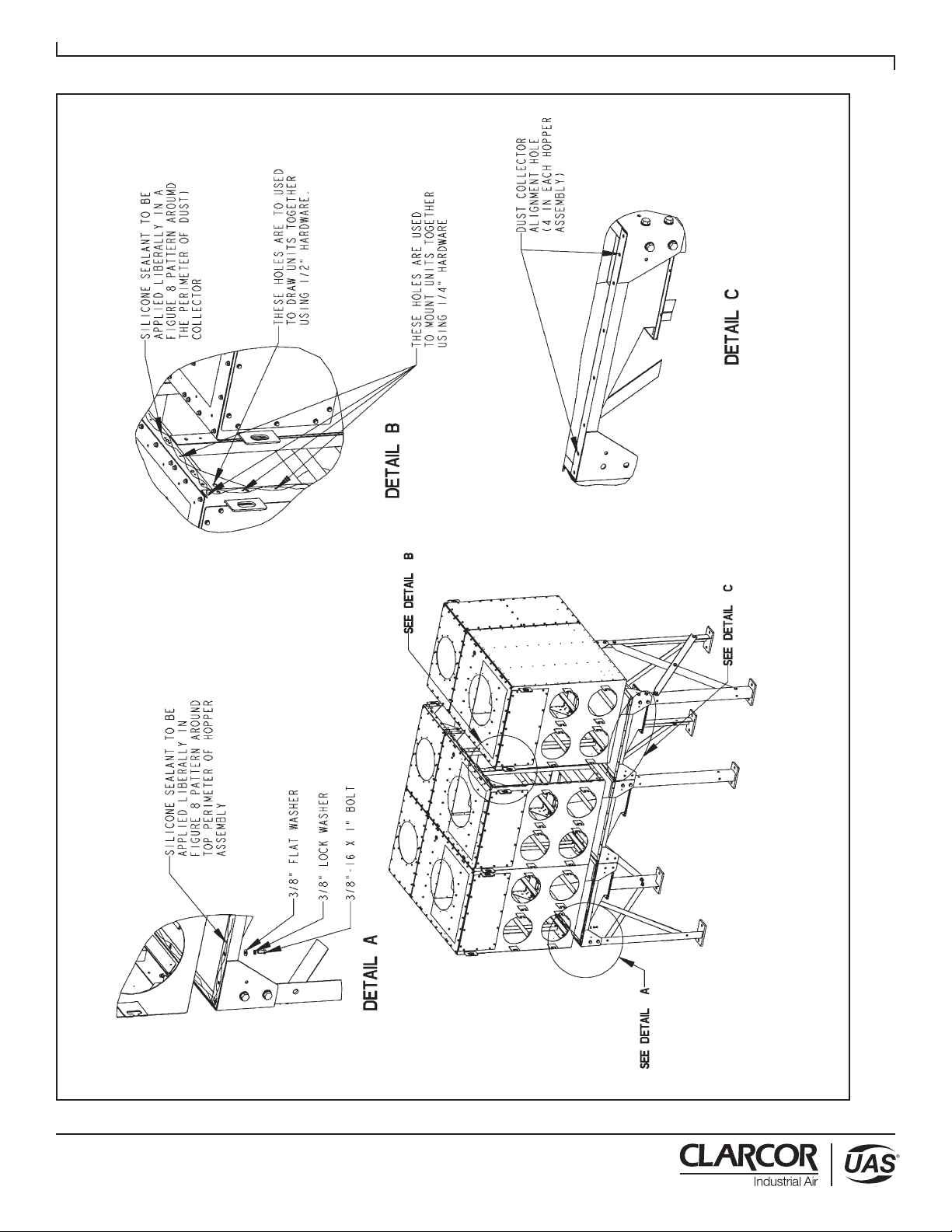
3.3.2 FULLY ASSEMBLED FILTER MODULE
SECTIONS
Apply two ribbons of sealant to hopper flange to
create “figure 8” pattern around mounting holes.
Refer to Figure 7, Detail A.
Place filter module onto hopper/leg assemblies (refer
to Figure 7). Drift pins will also be useful for locating
the filter module section onto the hopper.
NOTE: Each hopper assembly is equipped with four
1/2” (13mm) pry locations – two holes on front
flange and two holes on rear flange. Refer to
Figure 7, Detail C, to aid in aligning the hopper
flange with the module flange.
With filter module still supported, use hardware (refer
to Figure 7, Detail A) to bolt the hopper and filter
module together. Securely tighten all hardware at the
filter module and hopper. Recheck leg assembly sway
braces to ensure they are tight. Install fasteners (bolt,
flat washer, lock-washer, nut) to all four pry locations.
Disconnect lifting slings and spreader bars used for
installation.
3.3.3 MULTIPLE, BOLT-TOGETHER MODULE
SECTIONS (APPLIES TO 4 OR MORE
MODULES)
For units that have multiple bolt-together module
sections, remove the row of filters from the modules
nearest the bolting flange (refer to Section 5.1).
Protect the doors and filters removed by placing in a
safe area away from work area. Identify the different
module sections. There are left (bolt flange on right
side), right (bolt flange on left side) and possibly
center (bolt flanges on both sides) module sections.
Install all hopper/leg assemblies as previously
described in Section 3.3.1.1 and 3.3.1.2.
Apply two ribbons of sealant to hoppers that are
located under the dust collector section that is being
installed (refer to Figure 7, Detail A).
CRUSH AND ELECTROCUTION HAZARD
In preparing to attach the filter module to the hopper,
connect lifting slings and spreader bars to all filter
module lifting lugs with clevis pins. Distribute the
load evenly. Location must be clear of all
obstructions, such as utility lines or roof overhangs.
Place the appropriate filter module onto hopper/leg
assembly to which the sealant has been applied,
positioning filter module corner holes over alignment
holes (refer to Figure 7, Detail C). Drift pins will also
be useful for locating the filter module section onto
the hopper.
NOTE: Each hopper assembly is equipped with four
1/2” (13mm) pry locations – two holes on front
flange and two holes on rear flange. Refer to
Figure 7, Detail C, to aid in aligning the hopper
flange with the module flange.
With filter module still supported, use hardware (refer
to Figure 7, Detail A) to bolt the hopper and filter
module together. Securely tighten all hardware at the
filter module and hopper. Recheck leg assembly sway
braces to ensure they are tight. Install fasteners (bolt,
flat washer, lock-washer, nut) to all four pry locations.
!DANGER
!WARNING
!WARNING
7
Revised 04/15 SFC
Cartridge Dust Collector
FIGURE 4
Single Hopper, SFC
44-10309-0001

8
Revised 04/15 SFC
Cartridge Dust Collector
FIGURE 5
Multiple Hopper, SFC
44-10309-0002

9
Revised 04/15 SFC
Cartridge Dust Collector
FIGURE 6
Multiple Hopper, SFC
44-10309-0003
10
Revised 04/15 SFC
Cartridge Dust Collector
FIGURE 7
Multiple Modules, SFC
44-10310-0001
11
Revised 04/15 SFC
Cartridge Dust Collector
Disconnect lifting slings and spreader bars used for
installation.
Apply sealant to the next hoppers that will receive a
filter module (refer to Figure 7). Apply sealant to the
side bolting flange of the next filter module to be
installed using the “figure 8” pattern (refer to Figure 7,
Detail B). Place this module on its hopper. Use the
hardware provided (refer to Figure 7, Detail B).
Place this module on its hopper. Use the hardware
provided (refer to Figure 7, Detail B) and bolt the
module sections together. Bolt the filter module to
the hopper (refer to Figure 7, Detail A). Securely tighten
all hardware at the filter module and hopper. Recheck
leg assembly sway braces to ensure they are tight.
Install fasteners (bolt, flat washer, lock-washer, nut) to
all four pry locations..
Disconnect lifting slings and spreader bars used for
installation.
Repeat this process until all the module sections are in
place, securely fastened and anchored to the foundation.
Recheck all hardware connections to make certain they
are securely tightened. Remove lift slings and spreader
bars and clear all tools from the work area.
NOTE: Make certain all bolts (including the anchor
bolts) are properly tightened before proceeding
with the remainder of the installation.
Install all cartridge filters removed at the beginning
of the installation process and install the filter access
doors (refer to Section 5.1).
3.4 ELECTRICAL INSTALLATION
ELECTRICAL SHOCK HAZARD
All electrical work should be performed by a
qualified electrician in accordance with local
electrical codes. Disconnect electrical power before
installing or servicing any electrical component.
GENERAL
Several types of standard electrical components can
be installed to control and monitor your dust collector.
A VFD or a motor starter circuit (combination starter
panel) is required to safely start and stop the system.
A properly sized circuit breaker or fused disconnect
is also required to safely work on and service the
electrical system. In addition, a 115/1/60 (2 amp)
control circuit is required for the pulse control panel.
Some or all of the above items may be included in the
controls package you purchased from UAS. Any one
of the following control combinations can be used:
• Motor starter with Digital Pulse Monitor (DPM) for
continuous pulse cleaning.
• Motor starter with Digital Pulse Control (DPC) for
on-demand pulse cleaning.
• VFD with DPM for continuous pulse cleaning.
• VFD with DPC for on-demand pulse cleaning.
Refer to UAS sales order to verify the control
configuration purchased with your unit and whether
additional items are required to control and operate
your system.
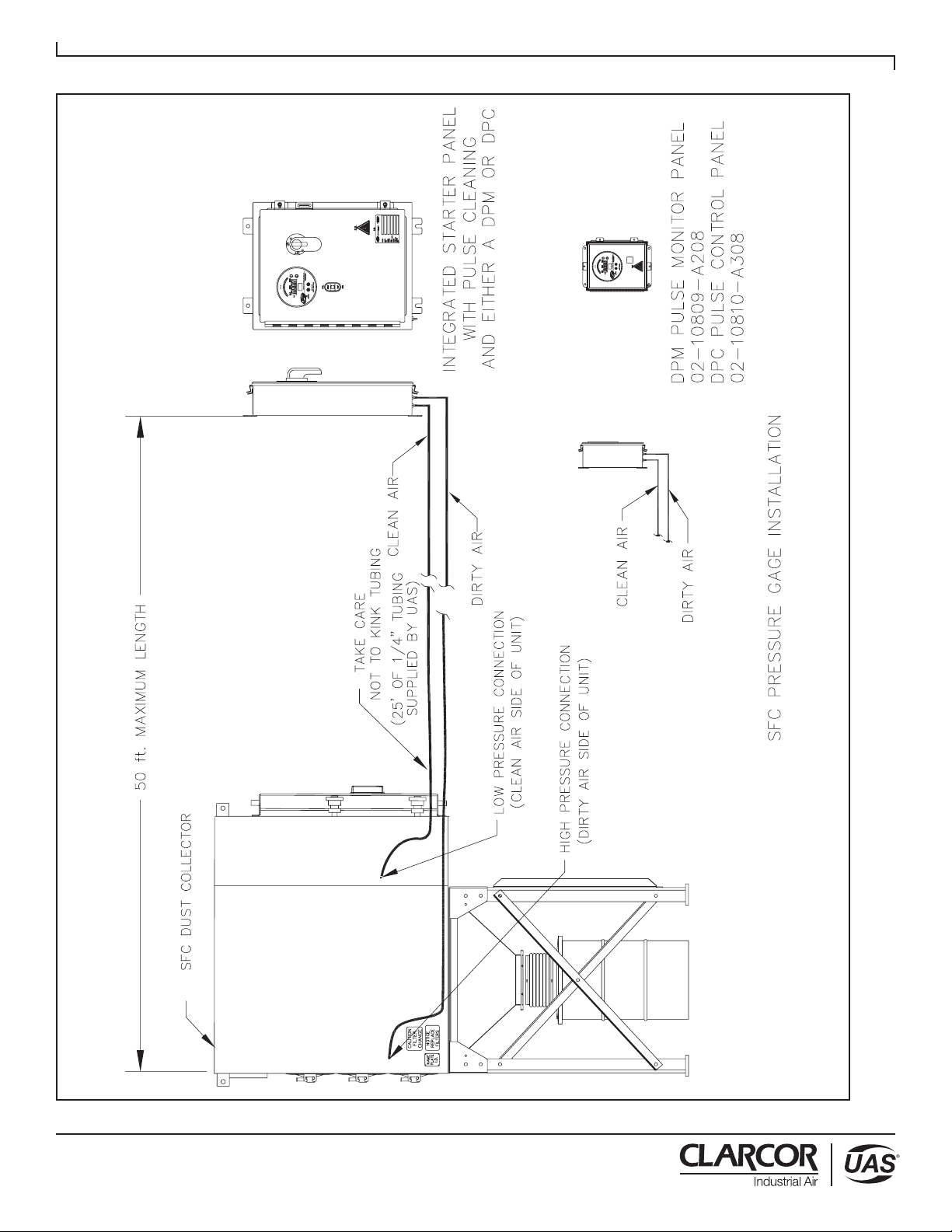
3.4.1 MOUNTING THE CONTROLS
Mount the VFD or combination starter panel for the
fan motor in a convenient location. It is recommended
that these controls be mounted on a wall or pedestal
in an area subject to minimal vibration and electrical
noise. Mounting hardware is provided by the
customer or the contractor. If the panel includes
the DPM or the DPC gauge and UAS timer control
board, then the location of the panel must within close
proximity of the dust collection unit as shown in Figure
8. For additional setup and installation information
refer to the VFD and/or DPM/DPC Owner’s Manuals
provided.
Avoid mounting the panel on the collector due to
vibration generated from blower assembly and the
pulsing system.
For all pulse control panels, connect the black plastic
pressure tubing (25’ [7.5 meters] provided by UAS) to
the panel fittings and the SFC unit. Connect the dirty air
plenum of the SFC to the high pressure port (dirty air)
on the panel as shown in Figure 8. Connect the clean
air plenum of the SFC to the low pressure port (clean
air) on the panel.
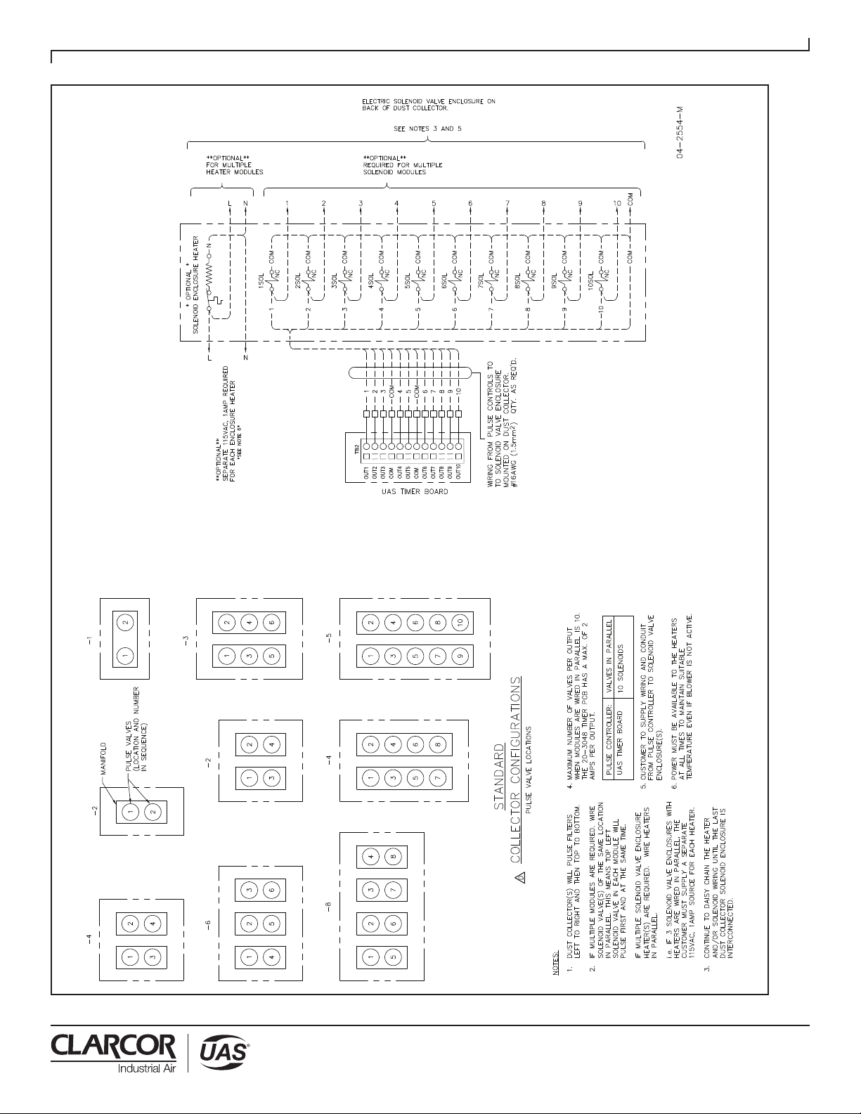
3.4.2 SOLENOID VALVE ENCLOSURE
WIRING
The solenoid valves at the dust collector must be
wired correctly to the pulse control panel. Refer to
Figure 9 when making connections from the pulse
control panel to the solenoid valve enclosure(s).
Example: Figure 9 shows the SFC having ten valve
locations per module. This means when the system
pulses, “1” is the first pulse in the sequence, “2” is
the second, “3” is the third, etc.
When multiple dust collector modules are installed,
daisy chain the wiring so that each solenoid valve
with the same module location will pulse at the
same time. This means all #1 solenoid valves are
connected together and wired to pulse control panel
“OUT 1,” #2 solenoid valves are connected together
and wired to pulse control panel “OUT 2,” etc. Refer
to Figure 9 for the SFC dust collector solenoid valve
wiring information. When cleaning, the pulse valves
sequence left to right, top to bottom.
Unless specified on the UAS sales order, the customer
will supply interconnecting material (conduit, wiring,
etc.) from the pulse control panel to the SFC.
CAUTION
!DANGER
12
Revised 04/15 SFC
Cartridge Dust Collector
FIGURE 8
SFC Pressure Gauge Installation
44-10333-0001, Rev A
13
Revised 04/15 SFC
Cartridge Dust Collector
FIGURE 9
Solenoid Wiring to Pulse Controls for 2, 3, 4 and 5 Tier Units
14
Revised 04/15 SFC
Cartridge Dust Collector
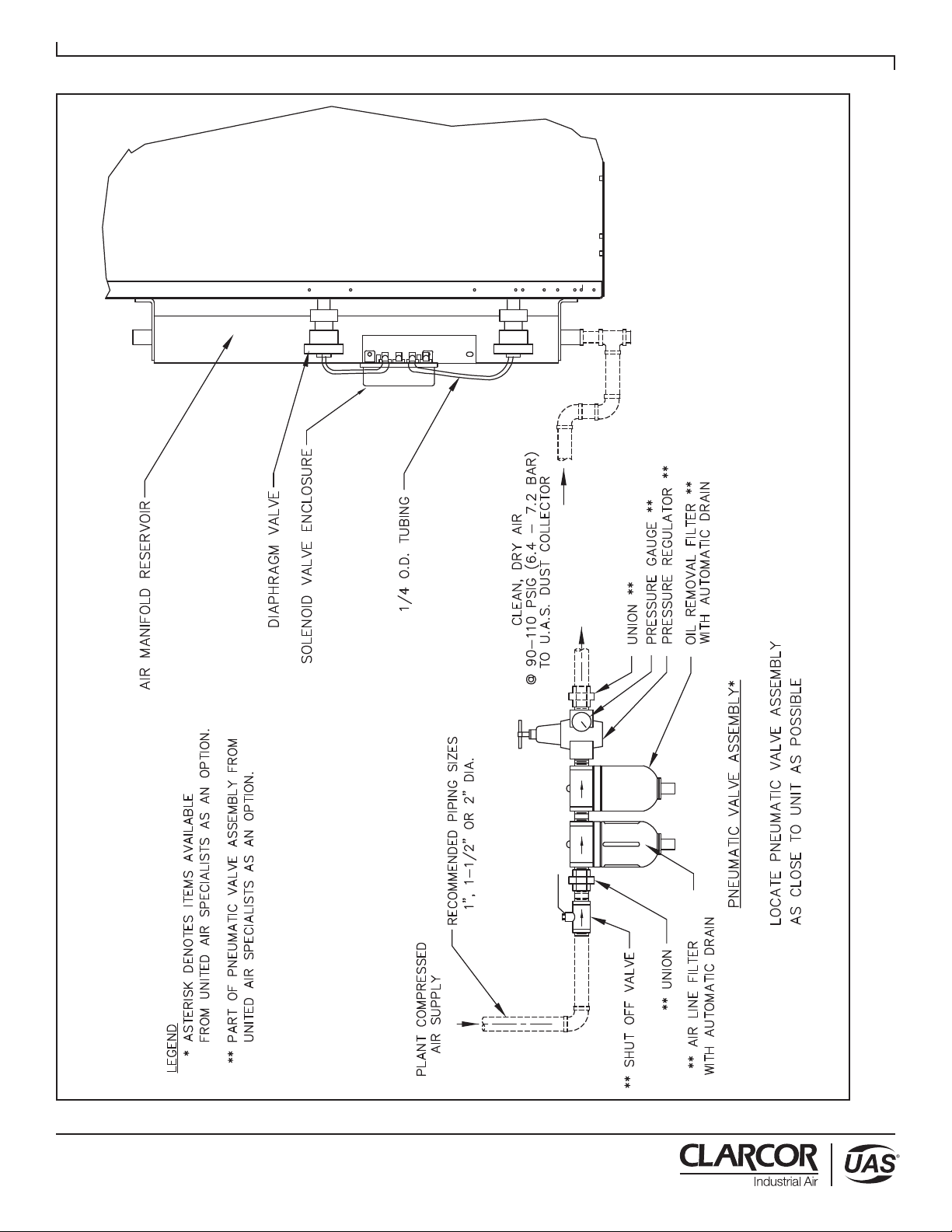
FIGURE 10
Pneumatic Valve Assembly
44-10332-0001

15
Revised 04/15 SFC
Cartridge Dust Collector
3.4.3 HEATER WIRING
In cold or damp environments, the heater serves to
prevent the electric solenoid valves from freezing
due to cold temperatures or condensation. If
optional solenoid valve heater is purchased, each
4 solenoid valve enclosures will contain a 70-watt
cartridge heater, 6, 8 and 10 solenoid valve
enclosures will contain a 120-watt cartridge heater
internally prewired to a thermostat.
The customer must provide a 100-130VAC,
50/60Hz, 1 amp power to the heater circuit for each
module. The power must be available to the module
solenoid valve enclosure(s) at all times (even when
the blower is shut down) to ensure temperature
regulation inside each solenoid valve enclosure
is continual. When multiple module solenoid
valve enclosures with heaters are installed, daisy
chain the wiring so that each heater will have
100/115VAC, 50/60 Hz at all times. Make certain
enough current is available to supply all heaters.
Example: If three solenoid valve enclosures are supplied
with cartridge heaters, make certain the voltage
supply can deliver 3 amps (1amp per heater).
3.5 COMPRESSED AIR CONNECTION
Do not allow water and/or oil from the compressed
air system into the compressed air manifold
reservoir. To ensure a clean, dry air supply,
especially when the unit is installed outdoors, a
water filter with automatic drain and a coalescing
filter should be installed (refer to Figure 10).
Clean, dry, 90-110 PSIG (6.2-7.6 BAR) compressed air
is required for the pulse cleaning system to function
properly. Compressed air consumption is noted on
the UAS sales drawing. A shut-off valve, pressure
regulator and pressure gauge should be installed close
to the SFC unit. UAS recommends dedicated oil and
water removal filters be used to ensure clean, dry air is
delivered to the pulse system. Contact your local SFC
representative for information about UAS’ Pneumatic
Valve Assembly. Refer to Figure 10 for recommended
compressed air piping and Table 1 below for proper
compressed air line sizing.
NOTE: Using Table 1, select the proper diameter
compressed air line pipe to supply your dust
collector. The final connection size is a female
1” NPT fitting on each module.
NOTE: Purge the compressed air line to remove any
debris prior to making the final connection to
the SFC compressed air manifold(s). Apply
pipe fitting sealant on all compressed air supply
pipe fittings and connections.
3.6 ASSEMBLY OF OPTIONAL EQUIPMENT
3.6.1 BLOWER PACKAGE INSTALLATION
TIP OVER HAZARD
Anchor dust collector to concrete pad prior to
installing blower assembly. Make certain all
hardware is properly tightened.
If a top-mount blower package was ordered, read
the manufacturer’s Installation and Operation Manual
completely before installing the blower. The blower
Installation and Operation Manual is attached to the
fan package. Perform all pre-installation checks prior
to installing the blower.
TIP OVER HAZARD
If blower package has a 20 HP (15 kW) motor or
larger, ensure the blower support legs are installed
beneath the clean air plenum of the module to
which the blower will be mounted.
For top-mount blower packages of 20 HP (15 kW) or
larger, an additional set of support legs is provided.
The additional support legs must be mounted under the
filter module supporting the blower package (refer to
Figure 11). Bolt the mounting plate to the bottom of the
appropriate clean air plenum with the hardware provided.
Bolt the leg assemblies to the mounting plate with the
hardware provided. Secure leg assemblies to the concrete
mounting pad with appropriate anchoring hardware.
Remove the clean air plenum cover plate on top of the
filter module and save the mounting hardware. Ensure
ribbon gasket remains on the unit. Lift blower package
using safe, suitable means and position blower base holes
over filter module holes with blower discharge pointing in
the desired direction. Secure with bolt/washer assemblies
previously removed. Top-mount blower packages include
a blower outlet damper. Install blower damper to outlet of
blower assembly with hardware provided.
If the blower package is a ground-mount blower, read
the manufacturer’s Installation and Operation Manual
completely before installing the blower. The blower
Installation and Operation Manual is attached to the
fan package. Perform all pre-installation checks prior
to installing the blower.
Outlet ducting from the SFC unit to the blower
package can be connected to either the top or bottom
clean air section access panel(s). It is recommended
industry practice to provide vibration isolation between
the blower inlet and the dust collector outlet ducting.
!DANGER
!DANGER
Pipe Diameter
1 inch (25mm)
1-1/2 inch (38mm)
2 inch (51mm)
Number of
Filter Section
Modules
1-3
3-5
+5
or
Distance of Supply Air
Piping Run From Main
Compressor Line
50 feet (15 meters)
100 feet (31 meters)
+100 feet (+31 meters)
Table 1
CAUTION
Table of contents
Other CLARCOR Dust Collector manuals

Popular Dust Collector manuals by other brands

Grizzly
Grizzly G0440 owner's manual

Hitachi
Hitachi RP 30Y Instruction manual and safety instructions

Steel City
Steel City 65110 user manual

Hafco Woodmaster
Hafco Woodmaster DC-90 instruction manual
 Spare parts")
Metabo
Metabo SPA 1100 (CH) Spare parts

Rikon Power Tools
Rikon Power Tools POWER TOOLS 60-1750 Operator's manual


Grizzly
Grizzly G0443HEP manual

DustEZE
DustEZE EC-560 Booklet

Harbor Freight Tools
Harbor Freight Tools 31810 Set up and operating instructions

Metabo
Metabo SPA 1200 Original operating instructions

Villager
Villager DM 14 P Original instruction manual

King Industrial
King Industrial KC-3109C instruction manual