CLARCOR UAS V Series User manual

VERSATILE/PORTABLE CARTRIDGE DUST COLLECTOR
V SERIES
MODELS - VB, VF, VP
OWNER’S MANUAL
Model VB
Model VP
Model VF

KNOW YOUR EQUIPMENT
READ THIS MANUAL FIRST.
Your V Series system should provide many years of trouble-free service. This manual will
help you understand the operation of your V Series unit. It will also help you understand
how to maintain it in order to achieve top performance. For quick future reference, fill in
the system and filter information in the spaces below. Should you need assistance, call
the United Air Specialists, Inc. customer service number shown below. To expedite your
service, have the following information available when contacting UAS.
UAS ORDER #:________________________________________________________________
UNIT MODEL #: _______________________________________________________________
UNIT SERIAL #: _______________________________________________________________
FILTER PART #:________________________________________________________________
SYSTEM ACCESSORIES:
______________________________________________________________________________
______________________________________________________________________________
______________________________________________________________________________
INSTALLATION DATE: __________________________________________________________
UNITED AIR SPECIALISTS, INC. CUSTOMER SERVICE
1-800-252-4647

TABLE OF CONTENTS
Page
SAFETY PRECAUTIONS……………………………………………………………ii
1. IMPORTANT NOTICE ................................................................................ 1
2. INTRODUCTION ........................................................................................ 1
2.1 Unit Nomenclature....................................................................................1
2.2 Description and Operation........................................................................1
2.3 Air Filtering Operation ..............................................................................1
2.4 Filter Cleaning Cycle ................................................................................1
3. SPECIFICATIONS ...................................................................................... 1
4. INSTALLATION .......................................................................................... 3
4.1 Off Loading and Inspection ..................................................................3
4.2 Installation ............................................................................................3
4.2.1 Portable Installation (VP Model) ..................................................3
4.2.2 Downdraft Table Assembly (VB Model) ........................................4
4.2.3 Fixed Unit Assembly (VF Model) ..................................................4
4.3 Pulse Cleaning ....................................................................................4
4.4 Electrical Installation ............................................................................4
4.4.1 Pulse Control Timer Board ..........................................................4
5. OPERATION ................................................................................................5
5.1 Start-Up ....................................................................................................5
5.2 Checklist ..................................................................................................6
6. SERVICE ....................................................................................................6
6.1 Filter Removal and Replacement ............................................................6
6.2 Dust Drawer Removal ..............................................................................7
6.3 After Filter Removal/Installation................................................................7
6.4 Servicing Direct Drive Blower ..................................................................8
7. ELECTRICAL ..............................................................................................8
7.1 Unit Control (On/Off) ............................................................................8
7.2 Cleaning Control (On/Off) ....................................................................8
8. TROUBLESHOOTING ................................................................................9
9. ILLUSTRATED PARTS LIST......................................................................10
10. APPENDIX ..............................................................................................12
i
IMPORTANT SAFETY INSTRUCTIONS
To reduce the risk of fire, electric shock, or injury, follow these basic precautions:
SAFETY PRECAUTIONS
We have provided many important safety messages in this manual and on the V Series source capture system. Always read
and obey all safety messages.
• Disconnect power before servicing.
• Do not use in explosive atmospheres.
• Do not collect emissions which are explosive.
• The V Series should not be used for support of
personnel or material.
• Operate only in a safe and serviceable condition.
• When collecting emissions from metal grinding or other
spark producing processes, care must be taken to
reduce any potential fire hazards.
• Do not allow operator to put cigarettes or any burning
object into the hood or ducting of the swing arm.
• Do not use the Swing Arm to move the portable air
cleaner (if applicable).
!
!DANGER
!WARNING
!CAUTION
CAUTION
This is the safety alert symbol.
This symbol alerts you to potential hazards that can kill or hurt you and others. All safety messages will follow the
safety alert symbol and the word “DANGER”, “WARNING”, or “CAUTION”. These words mean:
Indicates a hazardous situation which, if not avoided, will result in death or
serious injury.
Indicates a potentially hazardous situation which, if not avoided, could result
in death or serious injury.
Indicates a potentially hazardous situation which, if not avoided, may result
in minor or moderate injury.
CAUTION used without the safety alert symbol indicates a potentially
hazardous situation which, if not avoided, may result in property damage.
ii
1
Revised 08/09
V SERIES
Cartridge Dust Collector
1. IMPORTANT NOTICE
This manual contains specific information concerning
safety and precautionary measures. It is impossible to
list every potential hazard associated with dust
collection equipment or systems. Use of the equipment
must be discussed with a factory-trained, United Air
Specialists, Inc. (UAS) representative. As always,
please adhere to the most stringent safety procedures.
2. INTRODUCTION
Thank you for selecting United Air Specialists dust
collection equipment to assist you in your commitment
to a clean and safe environment.
2.1 UNIT NOMENCLATURE
Collection Method:
B = Downdraft Bench
F = Fixed Ducted Unit
P = Portable Unit w/ Swing Arm
Nominal Flow Rate:
750 = 750 CFM
1500 = 1500 CFM
Example:
VB-1500
This would be a downdraft bench with a nominal airflow
of 1500 CFM.
2.2 DESCRIPTION AND OPERATION
The V Series Dust Collection System is a high-
efficiency, cartridge dust collector designed to eliminate
airborne particles as they are generated. Contaminant
is captured at its source by a unit-mounted hood,
downdraft table or ducted inlet and then conveyed
through the cartridge filter section where it is collected.
Clean air is then recirculated back to the work area.
There are two primary cycles of normal operation for
the V Series — the air filtering operation and the filter
cleaning cycle utilizing a compressed air cleaning
system.
Figure 1 shows the basic system operation and
equipment of a V Series dust collector.
2.3 AIR FILTERING OPERATION
The contaminated air stream is drawn into the collector.
Once the dust-laden air enters the cabinet, it meets a
baffle plate that disperses the air and significantly
reduces the air stream velocity. This provides even
distribution of the air stream across the entire surface
area of the cartridge filters, allowing a uniform dust
cake to form. The reduced air stream velocity causes
the heavier particles to fall out and collect in the dust
drawer.
The air stream then passes through the cartridge filter
where it is stripped of the particles by the media.
Cleaned air flows through the center of the filter,
through the blower (and optional safety after filters and
exits through the rear of the cabinet, back into the
workplace.
2.4 FILTER CLEANING CYCLE
As the cartridge filter becomes loaded with
contaminants, it becomes necessary to clean the filter
to maintain adequate airflow.
The compressed air cleaning mechanism provides brief
bursts of compressed air into the cylindrical cartridge
filter. When actuated, the cleaning system directs 90-
100 PSI of customer supplied compressed air through a
pulse valve, into a blow pipe, creating a burst of
pressure through the inside of the cartridge filter. This
pressure dislodges the dust and reduces the pressure
drop across the filter so the system can maintain
adequate airflow.
3. SPECIFICATIONS
Air Collection Method:
The V Series dust collector comes in three basic dust
collection configurations.
1. Downdraft Bench Unit (VB)
2. Fixed Ducted Unit (VF)
3. Portable Unit w/ Swing Arm (VP)
Within these variations, the units have two different
models, the 750 and the 1500.
Cleaning Options:
There are two basic filter-cleaning options with the
V Series: a cleaning system utilizing compressed air
and an option where the filters are cleaned manually,
external to the dust collector cabinet by the customer.
Power Supply Options:
All 1-1/2 HP motors are available in 115-230/1/60 and
200,230,460,575/3/60. All 3 HP Motors are available in
200,230,460,575/3/60.
V X - X X X X
Collection Method
Nominal Flow Rate

2
Revised 08/09
V SERIES
Cartridge Dust Collector
61-10036-0001
Figure 1. Basic Unit Operation
Table 1 - V Series Unit Specifications
V SERIES UNIT SPECIFICATIONS
Model
Nominal
Airflow
(CFM)
VB-1500
VB-750
VF-1500
VF-750
VP-1500
VP-750
1500
750
1500
750
1500
750
Cabinet Dimensions (inches)
Width Depth Height
30-1/4
30-1/4
27-7/16
27-7/16
27-7/16
27-7/16
52-3/4
38-13/16
52-3/4
38-13/16
52-3/4
38-13/16
46-13/16
46-13/16
31-3/4
31-3/4
38-7/16
38-7/16
Shipping
Weight
(lbs)
440
365
405
335
450
375
Filter
Area
(ft2)
283
141
283
141
283
141
SCF Per
Pulse
1.3
1.1
1.3
1.1
1.3
1.1
Sound
Level
(dBA)*
77.5
79.3
81.6
74.4
81.6
74.4
* AMCA tested sound levels at 5 feet
Horsepowers of V Series units are dependent upon the flow requirement and can vary within the model size.
3
Revised 08/09
V SERIES
Cartridge Dust Collector
See below for the amperage requirements of your unit,
given the horsepower and power supply. The unit
nameplate will provide the electrical specifications of
your V Series system.
Motor HP
1.5
1.5
1.5
1.5
1.5
1.5
3
3
3
3
Power Supply
115/1/60
230/1/60
200/3/60
230/3/60
460/3/60
575/3/60
200/3/60
230/3/60
460/3/60
575/3/60
Amp Draw
16.4
8.4
5.2
4.8
2.4
1.9
8.4
7.8
3.9
3.1
Standard Unit Options:
HEPA After Filter, Carbon Odor After Filter, Pre-Wired
Motor Starter Panels
Filter Media Options:
Protura®Nanofiber, Protura®Nanofiber Fire Retardant,
Poly-Fiberglass, Spun-Bond Polyester
See Table 1 on page 2 to see the operating
specifications on your V Series system.
4. INSTALLATION
4.1 OFF LOADING AND INSPECTION
The V Series dust collector is shipped in two or three
containers depending on the configuration and options
selected. The first consists of the unit cabinet and
filtration components. Other container(s) may contain
the extraction arm, downdraft bench, etc.
Upon receipt of your unit, check for any shipping
damage. A damaged carton indicates that the
equipment may have received rough handling during
shipping that may have caused internal damage. Notify
your delivery carrier and enter a claim if any damage is
found.
Remove the filter access cover (located on the front of
the unit) by turning the black knob counterclockwise to
release the cover. Examine the seal between the
tubesheet (the vertical panel between the blower
section and the filter section) and filter. Make sure filter
or gasket has not become displaced during shipment
(refer to Section 6.1, Cartridge Filter Removal and
Replacement). Replace covers once inspection is
complete.
4.2 INSTALLATION
Different models of the V Series collector require
different assembly techniques. Please see the
techniques in the subsequent sections for
your V Series dust collector.
All models of the V Series will require minimum
clearances and access in order to perform routine
maintenance and service. Be sure to leave access for
filter removal, the dust drawer release lever and
blower/pulse valve access through the discharge
panel as shown in Figure 1.
4.2.1 PORTABLE INSTALLATION (VP MODEL)
The top of the V Series cabinet has either one set
of six (VP-750) or eight (VP-1500) threaded studs to
mount the swing arm. The necessary hardware is
pre-assembled the studs. When mounting the arms
on the unit, a ceiling height of about 10’ is required for
adequate clearance. Two people are suggested for
positioning the swing arm and securing into place.
1. Remove the swing arm from its shipping
containers and assemble per the swing arm
manual provided.
2. Remove nuts, lock washer and flat washer from
the studs on the cabinet (refer to Figure 2).
3. Position flange gasket(s) inside the protruding
studs on top of the unit (refer to Figure 2).
4. Position the swing arm mounting base into place
over the mounting studs. Ensure gasket is
positioned properly between unit and base
flange. Secure swing arm to cabinet top with the
recently removed hardware (refer to Figure 2).
Avoid sharp pulls on the arm or hood as well as
over-tightening the pivot section since damage to
the arm components could result.
Figure 2. Swing Arm Installation Detail
Table 2 - Unit Amperage Requirements
61-10036-0002
4
Revised 08/09
V SERIES
Cartridge Dust Collector
4.2.2 DOWNDRAFT TABLE ASSEMBLY (VB MODEL)
The V Series downdraft table (VB) comes packaged,
requiring some assembly before using. Follow the
steps below to complete the assembly.
1. Begin by securing the two side panels as shown
in Figure 3. Thread all four fastening knobs into
the cabinet leaving enough space for the side
panel to fit over top of threaded knob stud.
2. Lower each panel as shown onto the knob studs
and then tighten knobs until panel is secure.
3. Lower the back panel into rear aligning tray and
side panel guide slots.
4.2.3 FIXED UNIT ASSEMBLY (VF MODEL)
The fixed unit assembly typically requires some type of
customer-supplied ductwork to convey the dust from the
source to the collector. See Figure 4 for a typical
installation.
Care should be taken when sizing and laying out the
ductwork in order to minimize loses through the system.
Figure 3. Downdraft Table Installation Detail
61-10037-0001
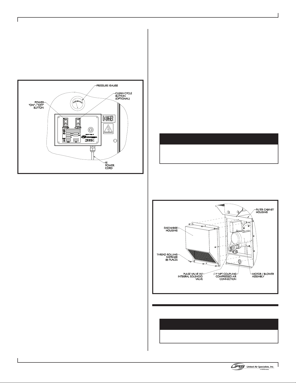
4.3 PULSE CLEANING
If your V Series system came with a cleaning system,
please review the following section for optimum
performance.
Provide a clean, dry, 90-110 PSIG compressed air
supply to the compressed air manifold. The supply
coupling (1" NPT) is located on the lower center of the
unit’s rear panel as shown in Figure 7. A reducer
bushing may be required for your supply line.
Compressed air supply to the unit can be a flexible
quick disconnect air line from a ceiling-mounted hose
reel or similar supplied plant air. The hose size can be
between 1/4” and 1” diameter.
The compressed air usage per cleaning cycle can be
found in Table 1. Note that the cleaning system will only
operate when the motor/blower is off. See Section 4.4.1
for adjustments available with the timer board.
4.4 ELECTRICAL INSTALLATION
The V Series unit has a wide variety of available
electrical options to best meet your needs. Take care
to ensure proper installation in whatever configuration
you have selected.
For units only requiring a 115-volt, single-phase power
supply, your unit will be supplied with a 15-foot power
cord and plug and is electrically ready for operation. If
the unit has a 230-volt, single-phase power supply, the
unit will be provided with a power cord but the customer
will be responsible for supplying and attaching the
appropriate plug.
For units requiring three-phase power, there are two
basic options. If UAS is supplying the motor starter, the
unit will be equipped with a 15-foot power cord without
a plug.
NOTE: All VP Series units come standard with a UAS
supplied starter
If the customer is supplying the motor starter, no cord,
motor overload protection or control transformer will be
provided.
Refer to Appendix A of this manual for the
recommended wiring diagrams of your V Series unit.
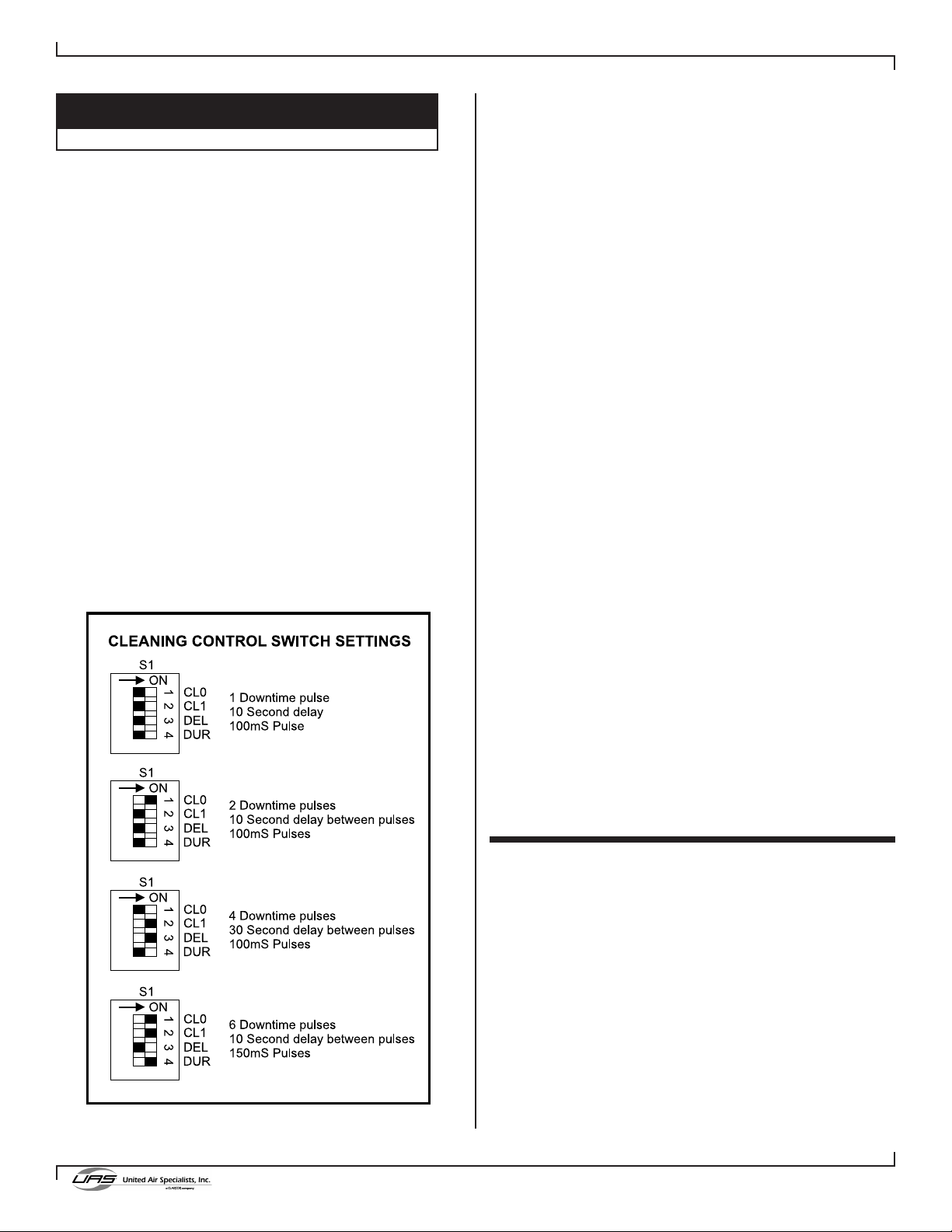
4.4.1 PULSE CONTROL TIMER BOARD
Before making any changes to the Pulse Control
settings, please read this section of the manual.
The Pulse Control timer board has been designed to
pulse a single solenoid valve that supplies a pulse of
compressed air to a dust collector filter. Unless
otherwise specified, the timer board is factory set to a
0.1 second pulse duration, 10 second pulse delay, and
1 downtime cleaning cycle.
Figure 4. Typical Fixed Unit Installation
61-10038-0001
5
Revised 08/09
V SERIES
Cartridge Dust Collector
DOWNTIME CLEANING OPERATION
1. Turn the CLEAN switch to the ON position. The PWR
light will be ON.
2. When the CLEAN CONTROL contacts (#13 and 14)
are shorted, the CLEAN light will be ON.
3. When the CLEAN CONTROL contacts open, the
CLEAN light will flash for the duration of the cleaning
cycle.
4. After the 60-second blower coast down delay, the
valve output (V and N) will turn on for the selected
length of time (100 or 150mS).
5. If more than one pulse is selected (2, 4 or 6), there
will be a 10 or 30 second delay as selected between
the pulses.
6. When the cleaning cycle is complete, the CLEAN
light will turn OFF and the control board will wait for
the CLEAN CONTROL contacts to close again.
If at any time during the cleaning cycle the CLEAN
CONTROL contacts close, the cleaning cycle will be
aborted, the CLEAN light will stop flashing, and the unit
will wait for the CLEAN CONTROL contacts to open.
The unit will NOT remember how many pulses were
previously performed; and the cleaning cycle will start
again from the beginning.The position of the four
"white" switches on S1 determine the number of pulses,
the length of the pulse and the delay between pulses.
The position of the switches are read when the CLEAN
CONTROL contacts open, and will not affect the
cleaning cycle if changed during a cleaning cycle. (See
Figure 5 for Cleaning Control Switch Settings)
Upon motor/blower shutdown, downtime cleaning will
only be performed if the CLEAN SWITCH is in the ON
position before the motor/blower is turned OFF. During
downtime cleaning, the CLEAN light will flash for the
duration of the cycles selected.
5. OPERATION
5.1 START-UP
1. Position unit in desired location.
NOTE: Do not attempt to move the portable unit by
pulling on the swing arm or hood. Use the full-
width, bar-type handle on the back of the unit to
push the V Series into the desired location. After
the unit is situated, use the locks on the rear
wheel casters to secure the unit.
2. Plug the unit into a properly grounded electrical
receptacle.
A separate motor starter auxiliary isolated dry contact
must be supplied with the motor/blower starter for all 3-
phase models and wired to terminals #13 and #14 of
the pulse control board.
TIMER BOARD SPECIFICATIONS
Power Requirement: 100-132VAC, 1 amp, 50/60Hz.
Operating Temperature: -40ºF to 140ºF (-40ºC to 60ºC),
Output: 1 solid-state switch at 1 amp max.
Required Input: Motor starter or switch isolated
normally open contact.
CLEANING CYCLE ADJUSTMENTS/TIMES
(See Figure 5 for Cleaning Control Switch Settings)
Blower coast down delay: 60 seconds, non-adjustable
Number of downtime pulses performed upon blower
shutdown: 1, 2, 4 or 6
Length of time between pulses: 10 or 30 seconds
Length of time output to valve is on: 100 or 150
milliseconds.
Figure 5. Cleaning Control Switch Settings
IMPORTANT
Information for units with 3-phase power
6
Revised 08/09
V SERIES
Cartridge Dust Collector
6. SERVICE
Figure 7. Rear Access
61-10039-0001
Collected dust may be hazardous. Consult proper
authorities for handling and disposal.
4. The filter monitor gauge should read between
0.1" and 0.5" w.g. while unit is operating with
clean filters.
5. The discharge plenum on the V Series collector
can be rotated in 90Ýincrements to direct the
discharge air in multiple directions. The discharge
housing will be factory installed with the discharge
pointing towards the floor as shown in Figure 7.
Collecting Particles
1. Locate the unit, arm and hood in the best position
to collect contaminants as generated by the
process or operation, and where operator
interference is minimal.
2. Position the hood to minimize the influence of
cross drafts from outside air sources or other
operations.
3. Position the hood slightly higher than the source,
with the face of the hood approximately 45° from
horizontal. The hood shape is designed for high-
velocity pick up. It should be located as close to
the source as practical and no further than 14-16"
from the contaminant source.
3. Check diaphragm valves to ensure proper pulse
cleaning. With the cleaning cycle activated, the valve
should pulse at approximately 10-second intervals.
Remove lid of control panel enclosure to view the
timer.
4. Check the filter monitor gauge at start-up. The
cleaning system should be activated when the gauge
has increased 0.5" w.g. above the start-up pressure
drop. Allow unit to pulse clean until the original
reading is achieved or until the gauge reading will
not decrease after six consecutive pulses.
5.2 CHECKLIST
1. Check the clean air outlet. Discharge air should
remain visibly clean. If a leak should develop, it will
be first noticed after a cleaning pulse as a puff of
dust.
2. Check pressure drop on the pressure gauge
(see Figure 6). Pressure drop across elements is
considered normal between 0.5-5.0" w.g. Pressure
drop will generally read between 1-2" for “seasoned”
filters.
The following procedure requires access to an area of
the unit where high voltage is present. Access should
be restricted to qualified personnel.
Figure 6. Control Panel Layout Detail
61-10039-0002
3. Turn the unit on by pushing the "Power" rocker
switch to the ON position (refer to Figure 6). On
3-phase units, fan rotation will need to be verified
by matching fan rotation with the rotation decal on
the blower housing. Rotation should be clockwise
as viewed from the motor or drive side. Any two
motor starter leads should be reversed if the
rotation is not correct.
7
Revised 08/09
V SERIES
Cartridge Dust Collector
1. Collected dust may be a potential fire hazard. Refer
to Section 1 of this manual.
2. Wear appropriate protective clothing.
3. Be environmentally aware of collected dust and its
proper disposal.
4. Press unit function switch to OFF position. Unplug
unit from electrical power source.
5. Disconnect compressed air supply to air manifold
inlet and bleed air supply from manifold.
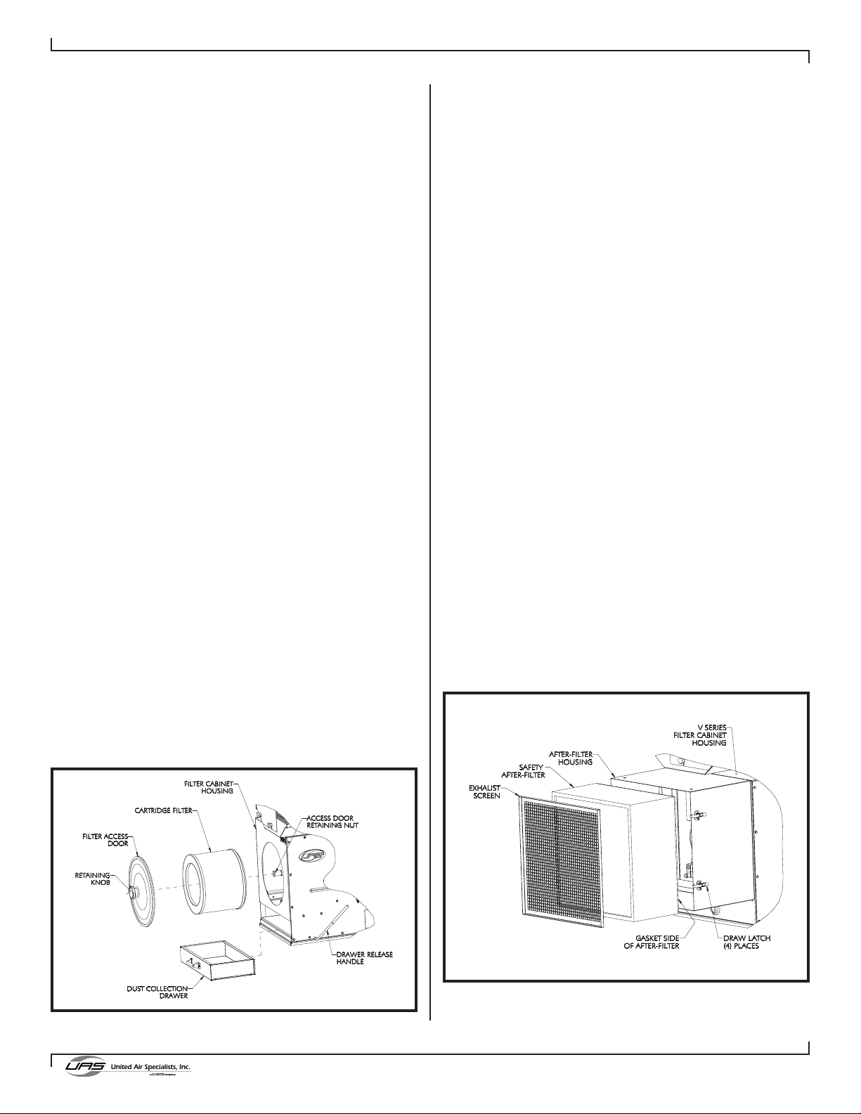
6.1 FILTER REMOVAL AND REPLACEMENT
As the V Series unit operates and the filter accumulates
dust, the flow rate of the unit will deteriorate. When the
pressure drop across the filter continuously reads
between 2"-3" or flow drops off to the point where the
dust generation process cannot adequately be
controlled, then it is time to change filters. To change
filters follow these steps:
1. Remove filter access cover by unscrewing the
retaining knob (see Figure 8). Tilt cover back away
from unit when freed from the retaining nut to trap
any fugitive dust on the inside of the access cover.
Dump dust into suitable disposal container.
2. Move filter from side to side to break gasket seal
between the filter and the tubesheet. Rotate the filter
180° to allow dust on top of the cartridge to fall into
the dust drawer.
3. Slide filter out along support rods and transfer to
suitable disposal container. Empty dust drawer as
described in Section 6.2.
4. Inspect tubesheet and make sure the gasket sealing
area is free of dust to ensure a proper seal.
5. Install a new filter element. Clean access cover
gaskets and reinstall cover by tightening the knob
securely to the retaining nut until the gasket is
adequately compressed.
Figure 8. Cartridge Filter Removal
61-10039-0003
6.2 DUST DRAWER REMOVAL
1. To access and remove the dust drawer located at the
base of the V Series unit, you must first unseal the
drawer by pulling the drawer release handle (see
Figure 8) toward the filter access side of the cabinet.
The drawer will move down and can be pulled out of
the front of the cabinet.
2. Dispose of the collected dust into a suitable
container. Any dust in the cabinet that was not
contained in the dust drawer should be vacuumed
out and disposed of.
3. Replace dust drawer by fully inserting into unit, and
reseal the drawer by pushing the drawer release
handle toward the control panel.
The collector should now be ready to operate. Reconnect
electrical power and air supply. Go through initial start-up
checklist to ensure proper unit performance.
6.3 AFTER-FILTER REMOVAL/INSTALLATION
If your unit was ordered with a HEPA or carbon after-filter,
there will be an additional filter housing bolted to the
discharge side of the V Series unit. The following steps will
allow you to remove and replace the after-filter as shown in
Figure 9. NOTE: After-filter housings for portable units (VP)
have a push handle located on the top of the housing.
1. Release the four draw latches located on the filter
housing to release the seal of the after-filter.
2. Remove the exhaust screen.
3. The after-filter will slide out of the housing as shown
in Figure 9. Keep in mind that the filter weight may
significantly increase from the collected material.
Dispose of filter properly.
Figure 9. After-Filter Removal
61-10040-0001

8
Revised 08/09
V SERIES
Cartridge Dust Collector
4. Install a new filter element by sliding it into the filter
housing with the gasket of the after-filter leading.
5. Replace the exhaust screen and secure the four
draw latches to seal the filter.
6.4 SERVICING DIRECT DRIVE BLOWER
To gain access to the direct drive motor/blower you
must first remove the discharge air plenum as shown in
Figure 7.
NOTE: The blower rotation should be clockwise when
looking at the motor from the discharge side of
the cabinet.
See the troubleshooting guide in Section 8 of this
manual for clues on motor/blower problems.
7. ELECTRICAL
Tables 1 and 2 provide a listing of V Series model
numbers and their corresponding voltage, motor
horsepower and full load amperage draw.
Please complete the provided blanks on the inside
cover of this manual. This will help you to identify your
unit when dealing directly with United Air Specialists or
your local UAS representative.
7.1 UNIT CONTROL (ON/OFF)
All units will have the blower controlled from the unit
control panel (refer to Figure 6). A black ON/OFF rocker
switch is provided to start/stop the blower.
7.2 CLEANING CONTROLS (ON/OFF)
Section 4.4.1 of this manual clearly outlines the
available settings and operation of the pulse cleaning
system.
Control of the reverse pulse cleaning system is by a
rocker switch on the unit control panel (refer to Figure
6). The pulse cleaning system operates independent of
the blower. This provides for off-line cleaning.
NOTE: Compressed air must be connected prior to
engaging cleaning system to prevent damage to
diaphragm valves.
Electrical Schematics
An electrical schematic was included with your unit in
this packet. Please secure the drawing to this manual
for future reference. A copy of the appropriate wiring
diagram is also affixed on the inside of the control
panel.

9
Revised 08/09
V SERIES
Cartridge Dust Collector
8. TROUBLESHOOTING
The Swing Arm slips from
set position.
The joints require adjustment. Adjust the joints (refer to Section 8.2 of the
Swing Arm Manual)
Grease the rotation socket.
A) Clean out blockage.
B) Reconnect hose.
C) Replace damaged hose.
D) Open arm damper.
E) Check downstream filters, replace or clean
as needed.
Strong resistance during
rotation of the arm.
Decrease in air volume.
Motor/blower won’t start
or won’t stay running.
Dust emissions from clean
air discharge
Insufficient airflow
Continual excessive
pressure drop (over 5.0”)
on filter monitor gauge.
Pulsing failure of
diaphragm valve.
Filter element installed incorrectly; gasket not
sealing.
Inspect and reinstall filter cartridge (refer to
Section 6.1).
Replace damaged filter element.
Check fan rotation to ensure clockwise
rotation (refer to Section 5).
Check for obstructions and clear.
Replace filters.
Cleaning system not being used at required
frequency. Increase frequency.
Check air supply pressure (should be 90-110
PSIG).
Replace filters.
Check continuity of solenoid coil with
ohmmeter. Replace if necessary.
Filter element damaged.
Fan rotation backwards.
Air inlet restricted.
Filters at end of service life.
Plugged filter elements.
Inadequate compressed air supply for
cleaning mechanism.
Filter elements at end of useful life.
Open solenoid valve.
Improper electrical supply. Refer to Section 7 for electrical specifications.
Starter overloadtripped. Reset overloads.
Lack of grease in the rotating socket.
A) The ventilation duct is plugged.
B) Flexible hose not properly connected to
arm tubes.
C) The flexible hose is damaged.
D) The Swing Arm damper is closed.
E) Packed filters or other
restriction in system.
PROBLEM POSSIBLE CAUSE RECOMMENDED SOLUTIONS
Timer does not operate.
“PWR” light dose not illuminate.
Downtime cleaning does not function.
PWR light not illuminated.
Downtime cleaning does not function.
PWR light illuminated but CLEAN light not
illuminated or flashing.
Downtime cleaning does not function.
CLEAN light flashing but valve does not
pulse.
1. Make certain 120VAC power is at terminals L and N.
2. Check fuses F1 and F2 for open circuit. If F1 is open, check wiring and
replace fuse. If F2 is open, replace board.
1. Make certain 120VAC power is at terminals L and N even after the
motor/blower is turned off. The PWR light should be illuminated.
2. In units with motor starters: make certain an isolated normally open
motor starter auxiliary contact is wired to terminals 13 and 14 (downtime
cleaning begins when the motor/blower starter is turned off.)
1. Check terminals V and N for 120VAC pulse. If no output when PULSE
light flashes, replace board. If 120VAC pulse is detected, check wiring,
valve coil and air supply.
PROBLEM RECOMMENDED SOLUTIONS

ELECTRICAL ENCLOSURE REPLACEMENT PARTS
10
Revised 08/09
V SERIES
Cartridge Dust Collector
ELECTRICAL ENCLOSURE REPLACEMENT PARTS
Item No.
1
2
3
4
Not Shown
General Description
CONTACTOR, MOTOR
OVERLOAD RELAY (3-PHASE, 1-1/2 HP, 208,230 V)
OVERLOAD RELAY (3-PHASE, 1-1/2 HP, 460 V)
OVERLOAD RELAY (3-PHASE, 1-1/2 HP, 575 V)
OVERLOAD RELAY (3-PHASE, 3 HP, 208,230 V)
OVERLOAD RELAY (3-PHASE, 3 HP, 460,575 V)
CONTROL BOARD, CLEANING SYSTEM
TRANSFORMER, STEP-DOWN TO 120V (200-208V)
TRANSFORMER, STEP-DOWN TO 120V (230-460V)
TRANSFORMER, STEP-DOWN TO 120V (575V)
SWITCH, ROCKER, DPST
UAS Part No.
23-3124-9
23-3124-5.0
23-3124-3.1
23-3124-2.4
23-3124-8.5
23-3124-4.0
20-3232
21-1275-050
21-1274-050
21-1276-050
20-2920
61-10041-0002
Panel shown is with UAS supplied starter
11
Revised 08/09
V SERIES
Cartridge Dust Collector

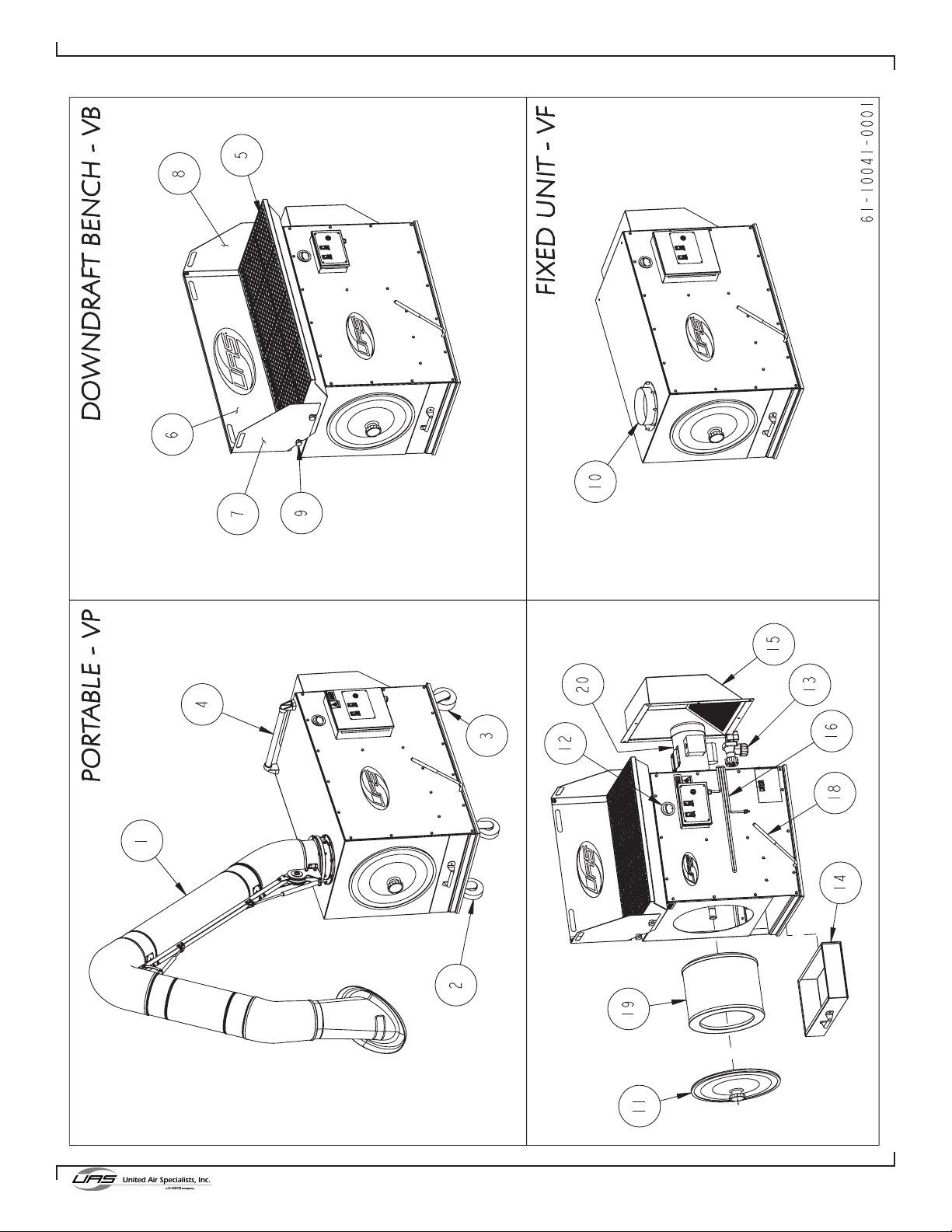
PORTABLE V SERIES REPLACEMENT PARTS
12
Revised 08/09
V SERIES
Cartridge Dust Collector
Item No.
1
2
3
4
General Description
SWING ARM, W/PARAVENT HOOD, 6" DIA. x 7' EXTENSION
SWING ARM, W/PARAVENT HOOD, 6" DIA. x 10' EXTENSION
SWING ARM, W/PARAVENT HOOD, 6" DIA. x 14' EXTENSION
SWING ARM, W/PARAVENT HOOD, 8" DIA. x 7' EXTENSION
SWING ARM, W/PARAVENT HOOD, 8" DIA. x 10' EXTENSION
SWING ARM, W/PARAVENT HOOD, 8" DIA. x 14' EXTENSION
CASTER RIGID, 5" DIA.
CASTER-SWIVEL, 5" DIA.W/LOCK
PUSH HANDLE BAR
UAS Part No.
15-10028-000M
15-10029-000M
15-10030-000M
15-10031-000M
15-10032-000M
15-10033-000M
17-0026
17-0027
39-0268
Item No.
5
6
7
8
9
General Description
GRATE, BENCH, VS1500
GRATE, BENCH, VS750
PLATE, REAR, BENCH,VS1500
PLATE, REAR, BENCH,VS750
SIDE PLATE, FMD, LEFT,BENCH
SIDE PLATE, FMD, RIGHT, BENCH
KNOB,5-LOBE W/ STUD,1/4-20
UAS Part No.
10-11872-0001
10-11873-0001
10-11876-0001
10-11877-0001
10-11880-0001
10-11881-0001
39-10026-0001
Item No.
10
General Description
SLIP COLLAR, 6” DIA
UAS Part No.
45-10017-0001
Item No.
11
12
13
14
15
16
18
19
20
General Description
VS,FILTER COVER,ASM
GAUGE-MINIHELIC,0-5" S.P.
VALVE,DIAPHRAGM,1" COMP.,DM25,W/ INT SOL
DUST DRAWER, VS 1500
DUST DRAWER, VS750
DISCHARGE HOUSING, VS
CONTACT UAS FOR AFTER FILTER HOUSING INFORMATION
CORD, POWER, 14-3, W/PLUG, SJT, 15FT (SINGLE PHASE POWER)
CORD, POWER, 14-3, SJT, 15FT (3-PHASE POWER)
GRIP,BLACK VINYL,1/2" ROD
SEE STANDARD FILTERS BELOW
CONTACT UAS FOR INFORMATION
UAS Part No.
02-10709-0001
07-0081
07-10002-0002
18-10716-0001
18-10720-0001
18-10728-0001
20-2813
39-10025-0001
FILTER
MOTOR/BLOWER
General Description
FILTER,CARTRIDGE,NANOFIBER,VS-750
FILTER,CARTRIDGE,NANOFIBER FIRE RETARDANT,VS-750
FILTER,CARTRIDGE,NANOFIBER,VS-1500
FILTER,CARTRIDGE,NANOFIBER,FIRE RETARDANT,VS-1500
FILTER,HEPA 99.97,23.375x23.375x11.5,UP GASK>
FILTER,HEPA 99.97,23.375x23.375x5.875,UP GASK>
FILTER,CHARCOAL,24x24x6
UAS Part No.
33-10097
33-10097-1
33-10098
33-10098-1
33-10081-0001
33-10082-0001
33-1219
PORTABLE V SERIES REPLACEMENT PARTS
DOWNDRAFT BENCH V SERIES REPLACEMENT PARTS
FIXED UNIT V SERIES REPLACEMENT PARTS
V SERIES COMMON REPLACEMENT PARTS
V SERIES STANDARD FILTERS
13
Revised 08/09
V SERIES
Cartridge Dust Collector
APPENDIX A. V SERIES WRING DIAGRAM
Figure 10. Wiring Diagram 120 Volt, Single Phase, Manual Clean
Figure 11. Wiring Diagram 120 Volt, Single Phase, Pulse Cleaning
Figure 12. Wiring Diagram 230 Volt, Single Phase, Manual Clean
41-2537
41-2538
41-2541
14
Revised 08/09
V SERIES
Cartridge Dust Collector
Figure 14. Wiring Diagram, Three Phase, Manual Clean w/ UAS Supplied Starter
Figure 13. Wiring Diagram 230 Volt, Single Phase, Pulse Cleaning
41-2542
41-2543
15
Revised 08/09
V SERIES
Cartridge Dust Collector
Figure 15. Wiring Diagram, Three Phase, Pulse Cleaning w/ UAS Supplied Starter
Figure 16. Wiring Diagram, Three Phase, Manual Clean w/ Customer Supplied Starter
41-2544
Figure 17. Wiring Diagram, Three Phase, Pulse Cleaning
w/ Customer Supplied Starter
41-2546
41-2545

©2004 United Air Specialists
Part No. 44-10448-0001
08/09
United Air Specialists, Inc.
reserves the right to change
design or specifications
without notice.
4440 Creek Road • Cincinnati, Ohio 45242 USA
National Phone: 1-800-252-4647
Telephone: (513) 891-0400 • Fax: (513) 891-4882
www.uasinc.com
UNITED AIR SPECIALISTS, INC.
LIMITED WARRANTY
UAS warrants to the original purchaser that all equipment will be free from defects in materials and
workmanship for one year from the date of shipment from UAS (three years for Smokeeter® and
VisionAir™ models other than CC and DC series) and that major structural components on SFC and MCB
series will be free from defects in materials and workmanship for ten years from the date of shipment from
UAS. This warranty applies only if equipment is properly installed, maintained, and operated under normal
conditions and does not apply to damage caused by corrosion, abrasion, abnormal use or misuse,
misapplication, or normal wear and tear. This warranty will be void with respect to equipment that is subject
to unauthorized repairs or modifications. UAS makes no warranty as to goods manufactured or supplied by
others. This warranty is subject to any limitations in UAS’ quotation and may not be modified except by a
written instrument signed by the President or Vice President of Sales of UAS.
THIS WARRANTY IS EXCLUSIVE AND IN LIEU OF ALL OTHER WARRANTIES, WHETHER
WRITTEN, ORAL OR IMPLIED, INCLUDING ANY IMPLIED WARRANTY OF
MERCHANTABILITY, FITNESS FOR A PARTICULAR PURPOSE OR NONINFRINGEMENT.
As Purchaser's exclusive remedy for any defects in the equipment, UAS will exchange or repair any
defective parts during the warranty period, provided such parts are returned, prepaid, to UAS' factory. The
obligation of UAS is limited to furnishing replacement parts F.O.B. UAS' factory or making repairs at UAS'
factory of any parts that are determined, upon inspection by UAS, to be defective. In no event will UAS be
responsible for labor or transportation charges for the removal, reshipment or reinstallation of the parts.
IN NO EVENT WILL UAS BE RESPONSIBLE FOR ANY SPECIAL OR CONSEQUENTIAL
DAMAGES.
This manual suits for next models
9
Table of contents
Other CLARCOR Dust Collector manuals

Popular Dust Collector manuals by other brands

Grizzly
Grizzly G0440 owner's manual

Hitachi
Hitachi RP 30Y Instruction manual and safety instructions

Steel City
Steel City 65110 user manual

Hafco Woodmaster
Hafco Woodmaster DC-90 instruction manual
 Spare parts")
Metabo
Metabo SPA 1100 (CH) Spare parts

Rikon Power Tools
Rikon Power Tools POWER TOOLS 60-1750 Operator's manual


Grizzly
Grizzly G0443HEP manual

DustEZE
DustEZE EC-560 Booklet

Harbor Freight Tools
Harbor Freight Tools 31810 Set up and operating instructions

Metabo
Metabo SPA 1200 Original operating instructions

Villager
Villager DM 14 P Original instruction manual

King Industrial
King Industrial KC-3109C instruction manual