Service Manual
SPECIFICATIONS
-1-
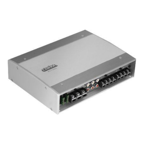
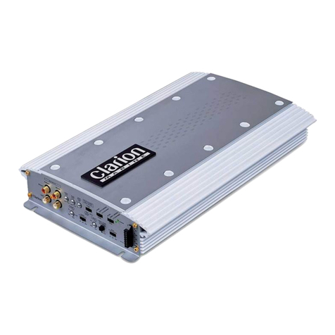
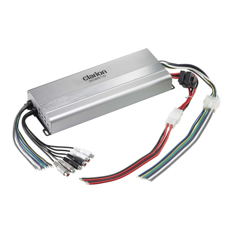
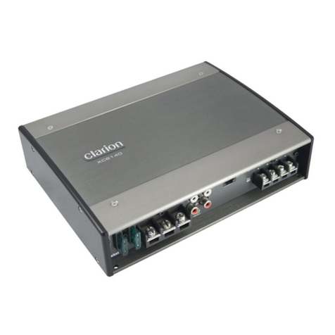
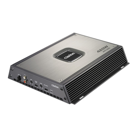
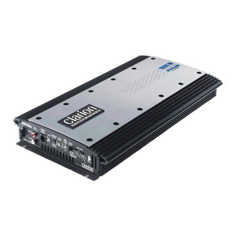
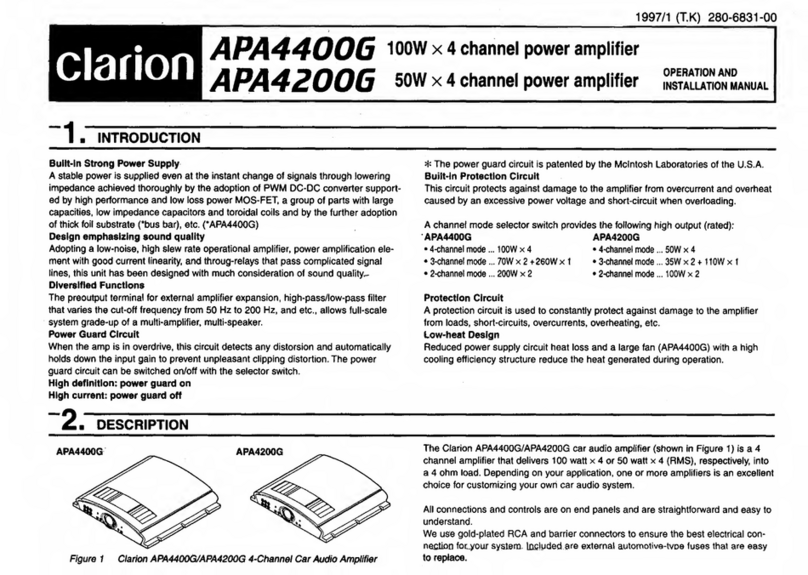
160W x 4 Channel Power Amplifier
Model APA4320
(GA-980E-51)
Clarion Co. Ltd.
50, kamitoda, Toda-shi, Saitama 335-8511, Japan
Service Dept: 5-66 Azuma, Kitamoto-shi, Saitama 364-0007 Japan
Tel:+ 81-48-541-2335/2432 Fax:+81-48-541-2703
Published by Service Dept.
298-6158-00
Printed in Taiwan
FEATURES
To engineers in charge of repair
or inspection of our products
APA4320
80W x 4(4-channel mode)
(20Hz to 20kHz,0.05%, 4ohm,
4-channel
simultaneous output)
80W x 2 + 2 30W x 1
(3-channel mode)
230W x 2(2-channel mode)
160W x 4
10Hz to 50kHz (+/-1.0dB)
0.025% (1kHz, 10W, 4ohm)
100dB
4ohm (2ohm~8ohm)
200mV to 6,000mV
14.4V
Negative
37(with 80Wx4 rateoutput)
1.6A(amplifier ON, noinput)
165(w) x 56(h)x 409(D)mm
3.9Kg
Rated Output
Maximum Power:
Frequency Response:
Harmonic Distortion:
S/N Rate:
Applicable
Speaker Impedance:
Input Sensibility
Power Source Voltage:
Ground
Power Consumption
Dimensions(mm):
Weight
:
:
:
:
:
NOTE
We cannot supply PWB withcomponent parts in
principle.
When a circuiton PWB hasfailure, please repairit by
component parts base. Parts, which arenot
mentioned in servicemanual, are notsupplied.
For improvement purposes,specifications and design
are subject tochange without priornotice.
1. Maximum PowerOutput 640W
2. Continuous Average Power Output 320W (80Wx 4
Into 4ohm 20Hzto 20kHz at0.05% THD)
3. Typical 2-Ohm Stereo115W x4 at 0.2%THD
4. Typical 2-Ohm BridgedPower 230W x2 at 0.2%THD
5. Bass ExtenderControl 0~15dB at45Hz
6. Adjustable 55Hz to 550Hz, 12dB/oct. High/Low-Pass
Crossover
7. Mixed- ModeOperation
8. 4-, 3-,or 2- ChannelOperation
9. MOSFET OutputDesign
10. Speaker LevelInputs
11. Double-SidedFR4 PC Board
1.Use specified parts.
The system usesparts with specialsafety features
against fire andvoltage. Use onlyparts with
equivalent characteristics whenreplacing them.
2.Place the partsand wiring backin their original
positions after replacementor re-wiring.
For proper circuitconstruction, use ofinsulation
tubes, bonding, gapsto PWB, etc,is involved. The
wiring connection androuting to thePWB are
specially planned usingclamps to keepaway from
heated and highvoltage parts. Ensurethat they are
placed back intheir original positionsafter repair or
inspection.
3.Check for safetyafter repair.
Check that thescrews, parts andwires are putback
securely in theiroriginal position afterrepair. Ensure
for safety reasonsthere is nopossibility of secondary
problems around therepaired spots.
4.Caution in removaland making wiringconnection to
the parts forthe automobile.
Disconnect the batteryterminal after turningthe
ignition key off.If wrong wiringconnections are made
with the batteryconnected, a shortcircuit and/or fire
may occur.
Before repair orinspection, make sureto follow the
instructions so thatcustomers and Engineersin charge
of repair orinspection can avoidsuffering any riskor
injury. Remodeling for whichwe shall notbe liable, the
onus of productliability (PL) shallnot be our
responsibility in caseswhere an accidentor failure isas
a result ofunspecified parts beingused or dueto
negligence during repair.
