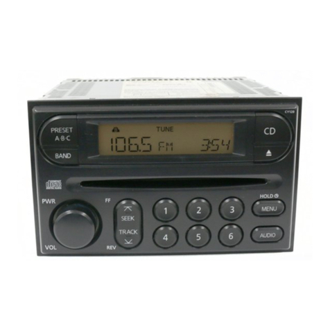
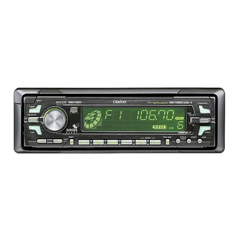
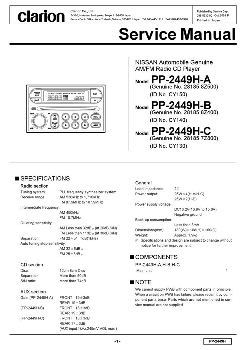
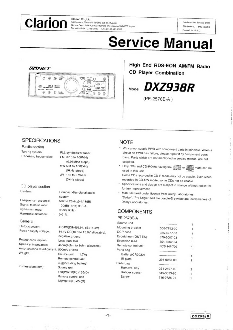
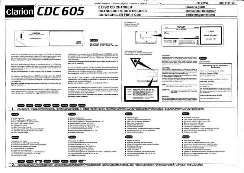
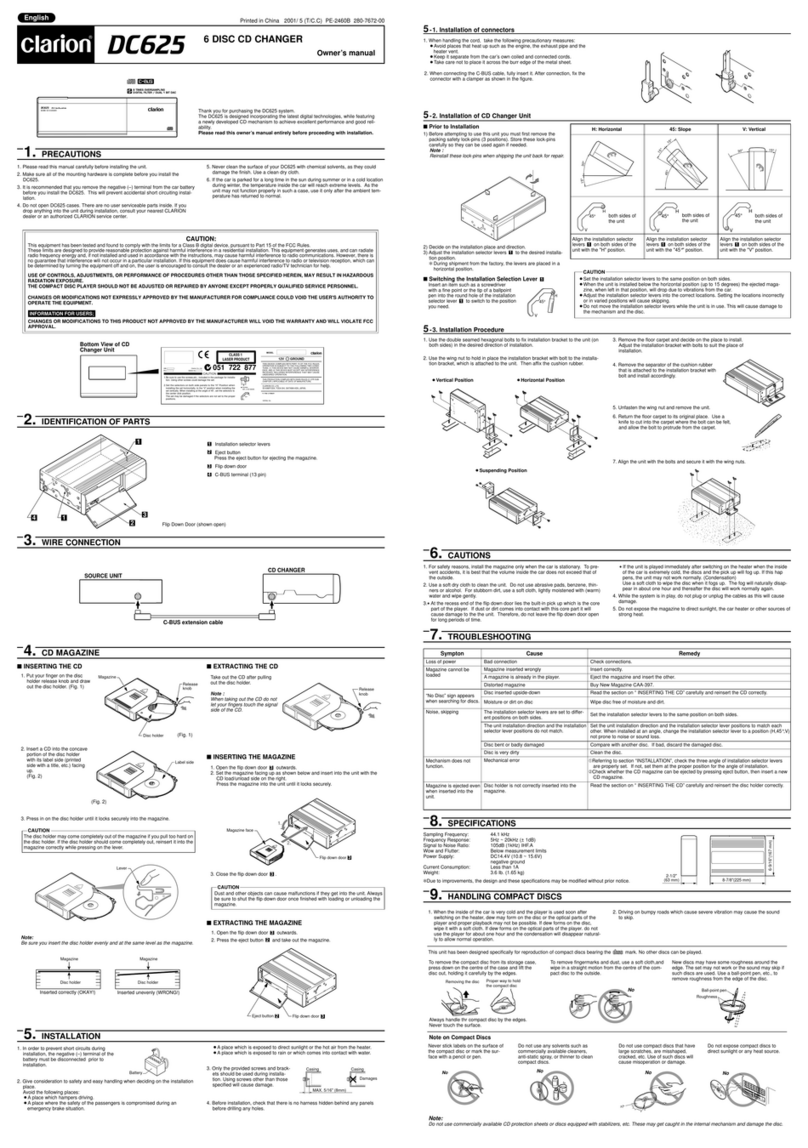
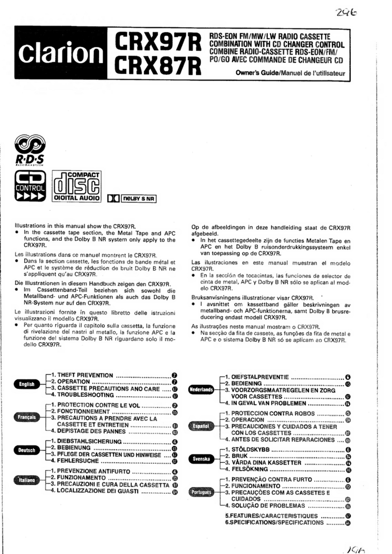
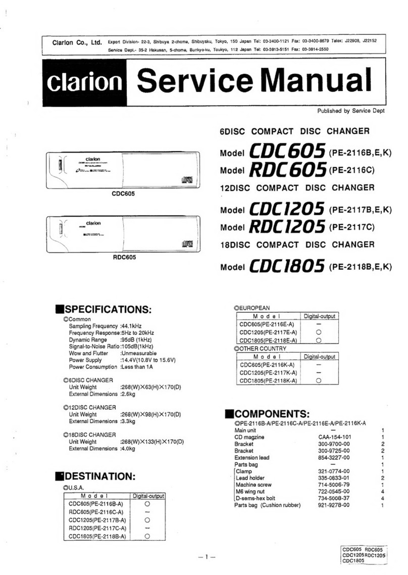
Clarion DC425 User manual

Clariofi
•Contents
English
1. PRECAUTIONS 2
2.
CONTROLS
'"
3
3.
BUTTON TERMINOLOGy.... .
.4
4.
FEATURES 5
5.
HANDLING COMPACT DiSCS 6
6.
DCP (Detachable
Control
Panel).
..
. 7
7.
REMOTE CONTROL. 8
8.
OPERATION..................................
..
10
9. TROUBLESHOOTING... .16
10.ERROR
DISPLAyS.....
.17
11.SPECIFICATIONS.. . .
.. ..
18
•Table des matieres
Franfais
1.
PRECAUTIONS............
.
19
2.
COMMANDES....
..
3
3.
NOMENCLATURE DES TOUCHES 20
4.
CARACTERISTIQUES
21
5.
MANIPULATION DES DISQUES COMPACTS
22
6.
CLAVIER DE COMMANDE AMOVIBLE (DCP) 23
7.
TELECOMMANDE
..
24
8.
FONCTIONNEMENT....
..
. . .
..
..
..26
9. DEPISTAGE DES PANNES...
..
32
10.AFFICHAGE DES ERREURS
..
.
33
11.SPECIFICATIONS.... .34
•
'ndice
Espaiiol
1.t.<PRECAUCIONES..... .35
2.t1 CONTROLES
....
.
..
..
..
3
3.
NOMENCLATURA DE LOS BOTONES.. .
36
4.
CARACTERISTICAS
37
5.
MANEJO
DE
LOS DISCOS COMPACTOS 38
,.
PANEL
DE
CONTROL DESMONTABLE (DCP) 39
7.
CONTROLADOR
REMOTO
..
.40
8.
OPERACION..........
..
.42
9.
SOLUCION
DE
PROBLEMAS .48
10.INDICACIONES
DE
ERROR
..
49
11.ESPECIFICACIONES 50
wDO~rn
DIGITAL AUDIO
AM/FM
CD
PLAYER
WITH
CD
CHANGER
CONTROL
•
RAi2HO
AfVl/fM
..
lECTEUR
CD
AVEC
COMMAr~DE
DE
·eHJ\NGEUs
..
R··
..
ti"'->ij····
•
RADIO
AM/FM
Y
REPRODUCTOR
CD
CON
CONTROL
DE
CAMBIADOR
DE
CD

_1_-
_PR_E_C_A_U_T_IO_N_S
------lJ
~
1.
When the inside of the car is very cold and
the player is used soon after switching
on
the heater, moisture may form on the disc
or the optical parts of the player and proper
playback may not be possible. If moisture
forms on the disc, wipe it off with asoft
cloth. If moisture forms on the optical parts
of the player, do not use the player for about
one hour and the condensation will disap-
pear naturally to allow normal operation.
2.
Driving on extremely bumpy roads which
cause severe vibration may cause the
sound to skip.
3.
This unit uses aprecision mechanism.
Even
in
the event that trouble arises, never
open the case, disassemble the unit, or
lubricate the rotating parts.
This equipment has been tested and found to
comply with the limits for aClass Bdigital
device, pursuant to Part 15 of the FCC Rules.
These limits are designed to provide reason-
able protection against harmful interference
in
aresidential installation. This equipment gen-
erates, uses, and can radiate radio frequency
energy and, if not installed and used
in
accor-
dance with the instructions, may cause harmful
interference to radio communications.
However, there
is
no guarantee that interfer-
ence will not occur
in
aparticular installation.
If
this equipment does cause harmful interfer-
ence to radio or television reception, which can
be determined by turning the equipment off
and on, the user is encouraged to consult the
dealer or an experienced radio/TV technician
for help.
USE OF CONTROLS, ADJUSTMENTS, OR PERFORMANCE OF PROCEDURES OTHER THAN
THOSE SPECIFIED HEREIN, MAY RESULT
IN
HAZARDOUS RADIATION EXPOSURE.
THE COMPACT DISC PLAYER
SHOULD
NOT BE
ADJUSTED
OR REPAIRED BY ANYONE
EXCEPT PROPERLY QUALIFIED SERVICE PERSONNEL.
Bottom
View
of
Source
Unit
MODEL
I I clarion
12V 8GROUND
AM 530-1710kHz/FM 87.9-107.9MHz
THIS DEVICE
COMPLIES
WITH PART 15 OF THE FCC RULES
OPERATION
IS
SUBJECT TO THE FOLLOWING TWO CONDITIONS
(1)
THIS DEVICE MAY NOT CAUSE HARMFUL INTERFERENCE AND
(2)
THIS DEVICE MUST ACCEPT ANY INTERFERENCE RECEIVED
INCLUDING
INTERFERENCE
THAT
MAY
CAUSE:
UNDESIRED
OPERATION
THIS
PRODUCTION
COMPLIES
WITH
DlIIIS
RULES
21
CFR
SUBCHAPTER
J
APPLICABLE
AT
DATE
OF
MANUFACTUHE
CLARION
CO
L
TO
50
KAMITODA.TODA
SHI.SAITAMA
KEN
JAPAN
SERIAL
No
c:=:=J
CHANGES OR MODIFICATIONS TO THIS PRODUCT
WILL
VOID THE
WARRANTY
AND
WILL
VIOLATE FCC APPROVAL.
Be
sure
to
unfold
and
read
the
next
page.
Veuillez
deployer
et
vous
a
fa
Cerci6rese
de
desplegar
yde
leer
la
pagina
siguiente.
DX425
2
2.
CONTROLS
I
ICONTROLES
Note: Be sure
to
unfold this page and refer
to
the front diagrams as you read each chapter.
Veufffez {
)VOi
~(!tio
/jdgu of vous r(Jf6rer
aux
schomas
quand
VOLlS /isez
chaque
chapifro.
Nota: Cuando lea los cap/tulos, despliegue esta pagina yconsulte los diagramas.
SOURCE UNIT//UNlOAD FUENTE
CD Insertion Slot
fente
d'insertlon
de
CD
Ranura de insercion del disco compacta
,@123
DISC~~~
12
10
8
11
6
54
3
1
15
DISPLAYITEMSIRUBi'ijLiJUES
iTEMES
DE
VISUALIZACION
3OX425

I
3.
BUTTON TERMINOLOGY
Note:
•
Be
sure to read this chapter referring to the front diagrams
of
chapter
2.
CONTROLS on page 3(unfold).
Names
of
Buttons
[I]
DCP Release Button
lliJ
Eject (
~)
Button
[gJ
SRCH (Search) Left and Right
«~
and
~»
[]]
Z(Z-enhancer plus) Button
Buttons
[1Q]
ROM
(Random) Button
[1J
POWER Button
FUNC (Function) Button
[1]
SS (Screen Saver) Button
[!]
BAND (Band) Button
[g]
Preset Buttons
(1
to
6)
TOP
(Top
Play) Button Direct Buttons
(1
to
6)
MAG
(Magazine) Button
[11J
ISR (Instant Station Recall) Button
[§]
SCN (Scan) Button
[H]
Rotary Knob
PSI
AS
(Preset Scan/Auto Store) Button
B]
A(Audio Mode) Button
[§]
RPT (Repeat) Button
LD
(Loudness) Button
[I] DISP (Display) Button
[f§]
Play/Pause (
~/II
)Button
MUTE Button
Display Items
DZ-EHCR PLUS (z-enhancer plus) indication
it
LD
(loudness) indication
fJ Operation status indication
II
MANU (manual) indication
*The frequency, play time, clock, T-SCAN,
D-
B
ROM
(random) indication
SCAN etc. are displayed.
11
mRPT (repeat) indication
Preset channel indication
(1
to
6)
Disc number indication
(1
to
6)
mSCN (scan) indication
*The disc numbers corresponding to the
1m
DISC indication
discs
in
the CD or MD changer light. mCD changer indication
II
ST (stereo) indication
4
DX425

4.
FEATURES
•Rotary
Encoder
Volume
Control
•DIN
Chassis
with
Detachable
Control
Panel
•CD-R/CD-RW
Compatible
•Z-ENHANCER PLUS
for
Sound
Creation
with
3
Adjustment
Modes (2-Band
P.EQ)
•MfiGI-TUNE@
FM
Reception System
•AM/FM Bands-1 AM, 3FM/18 FM/6 AM
Touchbutton
Memory
•8-Times
Oversampling
Digital Filter and
Dual1-Bit
D/A Converters
•Zero-Bit Detector™ Mute
Circuit
•Repeat/Random Play/lntro
Music
Scan
•
Blue
Negative LC
Display
•4-Channel RCA Line Level
Output
with
Fader
Control
DX425 5

_5
H_A_ND_L_I_NG_C_O_M_P_A_CT_D_IS_C_S_~
Note on Compact Discs
Never stick labels
on
the surface of the compact
disc or mark the surface with apencil or pen.
Do
not use any solvents such as commercially
available cleaners, anti-static spray, or thinner to
clean compact discs. 1
Do
not use compact discs that have large
scratches, are misshapen, or cracked, etc. Use
of such discs will cause misoperation or damage.
Do
not expose compact discs to direct sunlight
or any heat source.
Proper way to hold
the compact disc
Removing the disc
Ball-point pen
~
Roughness
This unit has been designed specifically for play-
back of compact discs bearing the
~p:~~
mark.
No other discs can be played.
To
remove the compact disc from its storage
case, press down on the center of the case and
lift the disc out, holding it carefully by the edges.
To
remove fingermarks and dust, use asoft
cloth, and wipe
in
astraight line from the center
of the compact disc to the circumference.
•
II!ii!ii!f!it:;;;;.
No
Always handle the compact disc
by
the edges.
Never touch the surface.
New discs may have some roughness around
the edges. The unit may not work or the sound
may skip if such discs are used. Use aball-point
pen, etc. to remove roughness from the edge of
the disc.
Note:
•Do not use commerciallyavailable CD protection sheets
or
discs equipped with stabilizers, etc. These
may
get
caught
in
the internal mechanism
and
damage the disc.
6
DX425

[6.
DCP (Detachable Control Panel)
Source
Unit
Front
DCP Rear Panel
Storing the DCP
in
the DCP Case
Hold the
OCP,
in
the orientation as shown
in
the
figure below, and put
it
into the supplied
OCP
case. (Ensure the OCP is
in
the correct orienta-
tion.)
OCP
OCP
case·
•The DCP can easily be damaged by shocks. After
removing it, place it in aprotective case and be
careful
not
to
drop
it
or
subject it
to
strong shocks.
•When the release button is pressed and the DCP is
unlocked, the car's vibrations may cause
it
to
fall.
To
prevent damage
to
the
DCP,
always store
it
in a
protective case after detaching it.
•The rear connector that connects the source
unit
and the
DCP
is
an extremely important part. Be
careful
not
to
damage
it
by pressing on
it
with fin-
gernails, pens, screwdrivers, etc.
Note:
•
If
the OCP is dirty, wipe off with asoft,
dry
cloth
only.
~*
The OCP
is
unlocked.
The control panel can be detached to prevent
theft. When detaching the control panel, store
it
in
the included
OCP
case to prevent scratches.
We
recommend taking the detachable control
panel with you when leaving the
car.
Removing the DCP
1.
Turn
off the power.
2.
Press the
OCP
Release button
0],
3.
Remove the
OCP.
Attaching the DCP
Insert the
OCP
into the right side of the source
uhit and press the left side to lock
it.
Do
not
insert
the DCP from the left side. Doing
so
may damage it.
DX425
7

7.
REMOTE CONTROL
Receiver for remote control unit
Signal transmitter
Operating range: 30"
in
all directions
Remote
Control
Unit
clarion
Inserting the Batteries
1.
Turn the remote control unit over, then slide
the rear cover
in
the direction of the arrow.
2.
Insert the AA (UM-3/1.5
V)
batteries that
came with the remote control unit facing
in
the directions shown
in
the figure, then close
the rear cover.
Notes:
Using batteries improperly can cause them
to
explode.
Take
note
of
the following points:
•When replacing batteries, replace both batteries with
new ones.
•
00
not short-circuit, disassemble
or
heat batteries.
•
00
not dispose
of
batteries into fire
or
flames.
•Dispose
of
spent batteries properly
Rear
side
~-~~
AA (UM-3/1.5 V)
Batteries
Rear cover
I
:~
:?
/;;:/
o
8OX425

Functions
of
Remote Control Unit Buttons
[TIJ
FUNC Turns power on and off. When pressed and held for 1second: Turns power off.
Switches between radio and
CD.
Increases and decreases volume (in all modes).
~
PLAY/PAUSE Turns mute on and off.
[gQ]
SEARCH Moves preset channels up and down.
Plays the first track.
Top play.
Moves tracks up and down.
When pressed and held for 1second:
Fast-forward/
fast-backward.
Switches between playback and pause.
Switches reception band.
[ID
BAND
DISC UP
PROG
TOP
ffID
VOLUME
~
MUTE Turns mute on and off. Switches between playback and pause.
~
ISR Recalls ISR radio station
in
memory.
Press and hold for more than 2seconds: Stores current station into ISR memory
(radio mode only).
~
DISP Switches among main display, sub display and clock display.
~
SCN
PS/AS Preset scan.
When pressed and held for 2seconds:
Auto store.
Scan play.
~
RPT
BLS No function. Repeat play.
[gIl
ROM
t.I MONI
N
No function. Random play.
*Some of the corresponding buttons on the source unit and remote control unit have different functions.
DX425
9

8.
OPERATION
Note:
•Be sure
to
read this chapter referring
to
the front diagrams
of
chapter
2.
CONTROLS on page 3(unfold).
Basic
Operations
When
this
unit is turned on, and stop-
ping the engine
of
acar with its volume raised
to
the maximum level may harm
your
hearing.
Be careful
about
adjusting
the
volume.
Turning
ON
the Power andAdjusting
the
Volume
1)
Press the POWER button
@J.
*
To
turn off the power, press the POWER button
Wfor 1second or longer.
2)
Press the FUNC button
@J
and select anoth-
er operation mode. Every time the FUNC but-
ton
@J
is
pressed, the display changes the
operation mode as:
Radio'"
CD ... (CD Changer) ... Radio
Notes:
•The operation mode not connected
to
the unit will not
be selected.
•If the CD mode
is
selected when no disc
is
inserted,
the display shows
"NO
DISC".
3)
Turning the Rotary knob
[B]
clockwise
increases the volume; turning
it
counterclock-
wise decreases the volume.
*The volume level
is
from 0(minimum) to 33 (max-
imum).
Setting the Z-enhancer Plus
This unit comes with 4types of sound tone
effects stored
in
memory. Select the one you
prefer.
*The factory default setting
is
"CUSTOM".
Each time you press Zbutton
[ID,
the tone effect
changes
in
the following order:
"B-BOOST"
"IMPACT" ...
"EXCITE"
...
"CUSTOM"
"Z+
OFF" ...
"B-BOOST"
...
•
8-800ST
:bass emphasized
•IMPACT :treble emphasized
•EXCITE :bass and treble emphasized
•CUSTOM :bass and treble adjustment
•Z+ OFF :no sound effect
10
OX425
Adjusting
the Tone
Press Abutton
[§
and select the item to adjust.
Each time you press Abutton
[§,
the item
changes
in
the following order:
•When
"B-BOOST"
is set
"B-BOOST"
... "BAL" ...
"FAD"
... Previous
mode
When "B-BOOST"
is
set, the bass adjustment
value can be adjusted
in
the range of
-3
to +3
by
rotating the Rotary knob
[H]
clockwise or coun-
terclockwise.
•When "IMPACT" is set 1
"IMPACT" ... "BAL" ...
"FAD"
... Previous
mode
When "IMPACT"
is
set, the treble adjustmEtnt
value can
be
adjusted
in
the range of
-3
to +3tJy
rotating the Rotary knob
[B]
clockwise or coun-
terclockwise.
•When "EXCITE" is set
"EXCITE" ... "BAL" ...
"FAD"
... Previous
mode
When "EXCITE"
is
set, the bass and treble
adjustment value can
be
adjusted
in
the range of
-3
to +3
by
rotating the Rotary knob
[B]
clock-
wise or counterclockwise.
•When "CUSTOM" is set
"BASS"
...
"TREB"
... "BAL" ...
"FAD"
...
Previous
mode
•When
"Z+
OFF" is set
"BAL" ...
"FAD"
...
Previous
mode
When the Zbutton
[ID
is
pressed and hold for 1
second or longer with the tone effect set to "B-
BST", "IMPACT" or "EXCITE", the sound char-
acteristics become flat and the indication "FLAT"
is
shown
in
the display.
Adjusting
the
Bass
This adjustment can be performed when the
Z-
enhancer Plus
is
set to "CUSTOM".
1)
Press Abutton
[§
and select "BASS".
2)
Turning Rotary knob
[B]
clockwise empha-
sizes the bass; turning
it
counterclockwise
attenuates the bass.
*The factory default setting
is
"0".
(Adjustment
range:
-6
to
+6)
3)
When the adjustment
is
complete, press A
button
[§
several times until the function
mode
is
reached.

Adjusting the Treble
This adjustment can be performed when the Z-
enhancer Plus is set to "CUSTOM".
1) Press Abutton [j]] and select
"TREB".
2) Turning Rotary knob
[H]
clockwise empha-
sizes the treble; turning it counterclockwise
attenuates the treble.
:;:
The factory default setting
is
"0". (Adjustment
range:
-6
to +6)
3)
When the adjustment is complete, press A
button [j]] several times until the function
mode is reached.
Adjusting the Balance
1)
Press Abutton [j]] and select "BAL".
2) Turning the Rotary knob
[H]
clockwise empha-
sizes the sound from the right speaker; turn-
ing it counterclockwise emphasizes the sound
from the left speaker.
:;:
The factory default setting
is
"0".
(Adjustment
range: L13 to R13)
3)
When the adjustment
is
complete, press A
button [j]] several times until the function
mode
is
reached.
Adjusting the Fader
1)
Press Abutton [j]] and select "FAD".
2)
Turning the Rotary knob
[H]
clockwise empha-
sizes the sound from the front speakers; turn-
tooing
it counterclockwise emphasizes the sound
rl
from the rear speakers.
:;:
The factory default setting
is
"0".
(Adjustment
range: F12 to R12)
3) When the adjustment
is
complete, press A
button [j]] several times until the function
mode
is
reached.
Loudness Effect
In
order to turn on/off the loudness effect, use
the LD button [j]] for 1second or longer. Every
time the LD button [j]]
is
pressed and held for 1
second or longer, the loudness effect switches
on and off.
:;:
When the loudness effect
is
on, the display will show
"LD".
Switching the Clock Display
Every time the DISP button
[1]
is pressed, the
display will change between the operation mode
and the clock display.
Setting the Clock
1)
Press the DISP button
[1]
to display the clock
display.
2) Press and hold the DISP button
[1]
for 1sec-
ond or longer.
3) Press the SRCH Left button
~,
then set the
current hour.
4) Press the SRCH Right button
~,
then set the
current minute.
5) Press the DISP button
[1],
then the clock is
set.
Notes:
•
If
you select another operation mode while you are
setting the clock, the clock setting operation will be
canceled.
•If you remove the vehicle's battery for acheck
or
repair, the clock will be reset, so you mustsetit again.
Turning the screen saver function
on
or
off
This unit is equipped with the function which
enables you to display avariety of patterns and
characters
in
the Operation status indication
f)
in
arandom order.
You
can turn this function on
or off.
:;:
The factory default setting is on.
While pressing the Disp button
[1],
press the SS
button
[IT]
to switch the function.
:;:
The following illustration shows one of the patterns
displayed when the screen saver function
is
set to on.
..
.. ..
.. ..
.
..
~
t···;
; ; ;
;;
.
..... .....
.
.....
DX425
11

Radio Mode Operations
FM Reception
For enhanced
FM
performance the MfiGI-TUNE@
tuner includes signal actuated stereo control and
Multipath noise reduction circuits.
Listening
to
the Radio
1)
Press the FUNC button
@]
to select the radio
mode, then the radio will be on.
2)
To
select apreset band, press the BAND but-
ton
W,
then select one of the preset bands
such as FM1, FM2, FM3, or AM. Every time
the BAND button W
is
pressed, the display
will change as:
F1
(FM1)
~
F2 (FM2)
~
F3
(FM3)
~
AM
~
F1
(FM1)
3)
Press the SRCH Left/Right button [lJ, then
the station at which there
is
abroadcast will
be selected (Seek selection).
Mute
Use this function to turn off the sound immedi-
ately.
Press the MUTE button [§]. The sound turns off
and "MUTE" appears
on
the display. Press the
MUTE button again to cancel the mute mode.
Manual Tuning
1)
Press the BAND button
W,
then select FM1,
FM2, FM3 or AM.
2)
Press and hold the BAND button
[Il
for 1sec-
ond or longer, then the display will show
"MANU", which means that amanual selec-
tion function
is
on.
3)
Press the SRCH Left/Right button [lJ and
select the right station.
Seek Tuning
1)
Press the BAND button
[Il,
then select FM1,
FM2, FM3 or
AM.
2)
If the "MANU"
on
the display
is
on,
press and
hold the BAND button
[Il
for 1second or
longer. When the "MANU" display
is
off, the
Seek Selection function
is
on.
3)
Press the SRCH Left/Right button [lJ, then
when it selects the station
in
which there
is
a
broadcast,
it
automatically stops.
12
DX425
Preset
Memory
Function
Preset Memory Function can store
up
to 24 sta-
tions: six stations for each of
FM
1,
FM2, FM3
and AM.
Note:
•When the present memory function
is
used, all the
content
of
the memory will be erased.
Manual
memory
function
1)
Press the BAND button [Il, and select the
band you want to store
in
the memory. )
2)
Press the SRCH Left/Right button [lJ then
select the station you want to store
in
the
memory. :
3)
Press and hold the Preset button [g] for 2
seconds or longer, then the station will be
stored
in
the memory.
Auto
store
function
(Automatic
Station Store)
1)
Press the BAND button [Il, then select the
band you want to store
in
the memory.
2)
Press and hold the
AS
button
ffiJ
for 2sec-
onds or longer, then the station at which the
reception
is
the strongest will
be
automatical-
ly stored
in
the memory.
Note:
•When the number
of
stations stored
is
less than six,
the previous content
of
the memory for each direct
button will be retained.
Preset Scanning (Preset Station Scan)
When the
PS
button
ffiJ
is
pressed, the preset
memory numbers flash and the stations are
tuned
in
for 7seconds each
in
the order
in
which
they were stored. Press the
PS
button
ffiJ
again
to cancel the preset scanning mode.
Instant
Station Recall (ISR)
With this function, aspecific radio station can
be
recalled from any mode.
ISR
memory
1)
Press the FUNC button [Il, then select the
radio mode.
2)
Select the radio station which you want to
store
in
the memory.
3)
Press and hold the ISR button
[J1)
for 2sec-
onds or longer.

Recalling ISR
Press the ISR button
[j]J
then the display will
show "ISR", then the radio station previously
memorized will
be
selected. Press the ISR but-
ton
[j]J
again to disengage the unit from the
Recalling ISR function.
CD Mode Operations
Loading aDisc
Insert the disc into the CD insertion slot with its
label side
up,
then the CD will start playing.
For 5-ineh (12 em) CD For 3-ineh
(8
em) single CD
*Press the DISP button [1], then the display will show
the play time.
Notes:
•Some CDs recorded in CD-R/CD-RW mode may
not
be usable.
..
..
...
..
i·~
..
.f
::::~
· .
· .
· .
·.
· .
· .
.
.
. . .
.. .
;
~
..
_;
*When inserting asingle CD
(3
"(8 cm)), insert it from
the center of the slot.
*When inserting asingle CD
(3
"(8 cm)), do not con-
nect
an
adapter.
Listening
to
the Disc already Inserted
Press the FUNC button
rn
to select the CD
mode, the CD will start playing.
Stopping (pausing) Playback
Press the Play/Pause button
[1]].
Press the Play/Pause button
[1]]
again to resume
playback.
Ejecting the CD
Press the Eject button
[ID,
then the CD will be
ejected.
Note:
•
If
the ejected CD is left as it
is,
it will be reloaded
after
15 seconds. However,
single
CDs
will
not
be
reloaded, so make sure to remove them.
~--
~
Initial Setting New Setting
--
(U.S.
standard) (outside U.S.)
----.
Frequency 10 kHz 9kHz
spacing
AM
---
----
--
Frequency 530 to
531
to
range
1,710kHz
1,629 kHz
---
--~--~
Frequency 200 kHz 50 kHz
spacing
FM
------
-
----
----
----
----
Frequency 87.9 to 87.5 to
range 107.9 MHz 108 MHz
Area Change
Use this function when you are using the car
stereo anywhere outside the U.S.
Switchable frequency spacing
This car stereo
is
initially set to tune
in
frequen-
cy intervals of
10kHz
for AM and 200 kHz for
FM,
the standard calibrations
in
the U.S. When
using the unit outside the U.S., use the following
procedure to switch the frequency range.
The table below lists the frequency specifica-
tions for the
U.S.
and other countries.
Switching the area change
Outside U.S. (New Setting)
While pressing the BAND button
@],
press the
SRCH Left button
rn,
then "outside
U.S."
will
be
selected.
Inside U.S. standard (Initial Setting)
While pressing the BAND button
@],
press the
tl
SR€H
Right button
rn,
then the "U.S. standard"
will
be
selected.
DX425
13

Top
Function
The top function allows the first track of the cur-
rent CD to be played.
Press
Top
button
@]
to play the first track (track
No.1) of
CD.
Selecting Tracks (songs)
Press the SRCH Left/Right button
[]].
~>:
Playback will start from the next track.
<
....
:Playback will start from the beginning of
the track currently playing. When this
button is pressed again, the CD will play
from the previous track.
Fast-Forward
and
Fast-Backward
Press and hold the SRCH Left/Right button
[]].
~>
:
To
fast-forward
<
....
:
To
fast-backward
*Pressing the SRCH Left/Right button for 1second or
longer will move forward or backward 5times faster
than normal
play,
and pressing
it
for 3seconds or
longer will do the operation 30 times faster.
Scan Play (Intra Music Scan)
Press the SCN button
[[],
then the display
shows "SeN", then the CD will play the first 10
seconds of each track of the whole disc. Press
the SCN button
[§J
again to disengage the unit
from scan
play.
*Ascan play will start from the track following the one
currently playing.
Repeat Play
Press the RPT button
[ID,
then the display shows
"RPT", then the track currently playing will
be
played repeatedly. Press the RPT button
[ID
again to disengage the unit from repeat
play.
Random Play
Press the
ROM
button
[1QJ,
then the display will
show "ROM", then the entire tracks
on
the disc
will be played at random. Press the
ROM
button
[Q]
again to disengage the unit from random
play.
14
DX425
CD Changer Operations
When aseparately sold CD changer
is
connect-
ed,
it
can
be
controlled from this unit.
Listening
to
the disc
Press the FUNC button
[]]
and select the CD
changer mode, then the CD starts playing.
Stopping (pausing) playback
Press the Play/Pause button [§].
Press the Play/Pause button [§] again to resume
playback.
I..)
f?
Selecting aCD
Each of the Direct buttons
[j]]
corresponds to a
disc loaded into the magazine.
•Selecting adisc from 1to 6
Press the corresponding Direct button
[j]]
(1
to
6)
to select the desired disc.
•Selecting amagazine from 1to 3(only when
there
is
disc
in
the magazine)
Press BAND button
@]
to select the desired
magazine.
*
If
aCD
is
not loaded
in
aslot of the magazine, press-
ing the Direct button
[j]
corresponding to its disc
number is invalid.
Selecting tracks (songs)
Press the SRCH Left/Right button
[]].
~>:
Playback will start from the next track.
<~:
Playback will start from the beginning of
the track currently playing. When this
button
is
pressed again, the CD will play
from the previous track.
Fast-forward
and
fast-backward
Press and hold the SRCH Left/Right button
[]].
~>:
To
fast-forward
<
....
:
To
fast-backward
*Pressing the SRCH Left/Right button
rn
for 1second
or longer will move forward or backward 3times faster
than normal
play,
and pressing it for 3seconds or
longer will do the operation 30 times faster.

Scan play
Press the SCN button
ffi],
then the display
shows "SCN", then the CD will play the first 10
seconds of each track of the whole disc. Press
the SCN button
ffiJ
again to disengage the unit
from scan
play.
*Ascan play will start from the track following the one
currently playing.
Disc scan play
Press and hold the SCN button
ffiJ
for 1second
or longer, then the display will show DISC indi-
cation
Em
and "SCN", and plays the first 10 sec-
onds of all the tracks of
all
the CDs
in
the CD
changer.
Press the SCN button
ffiJ
again to disengage the
unit from disc scan
play.
*Ascan play will start from the track following the one
currently playing.
Repeat play
Press the RPT button [§], then the display shows
"RPT", then the track currently playing will
be
played repeatedly. Press the RPT button [§]
again to disengage the unit from repeat
play.
Disc repeat play
Press and hold the RPT button [§] for 1second
or longer, then the display shows both the DISC
indication
Em
and "RPT", then the disc currently
bei~g
played will be played repeatedly.
Press the RPT button [§] again to disengage the
unit from disc repeat
play.
Random play
Press the
ROM
button
[1Q],
then the display will
show "ROM", then the entire tracks
on
the disc
will
be
played at random.
Press the
ROM
button
[1Q]
again to disengage the
unit from random
play.
Disc random playback
Press and hold the
ROM
button
[1Q]
for 1second
or longer, then the display will show both the
DISC indication
Em
and "ROM", then the entire
tracks of all the discs
in
the CD changer will be
played at random.
Press the
ROM
button
[1Q]
again to disengage the
unit from disc random
play.
Switching magazine
This function can be used only when the con-
nected CD changer can store amultiple number
of magazines.
Every time the MAG button
@]
is
pressed, the
next magazine will be selected.
Notes:
•Regarding MD Changer when aMD changer is used
with this unit, set the mode on the changer
to
'~"
(CD
Mode).
The
MD Changer can then be used
in
the CD chang-
er
mode. When used in this
way;
however, title can not
be displayed.
•Also, aCD changer cannot be connected concurrent-
ly with aMD changer.
DX425
15

9.
TROUBLESHOOTING
Problem
Power does not turn on.
(No sound
is
produced.)
Cause
Fuse
is
blown.
Incorrect wiring.
Solution
Replace with afuse of the same
amperage.
If
the fuse blows again,
consult your store of purchase.
------~-----
------
-~-----'
-------
IConsult your store of purchase.
~-------------t-------
---
-~-+-------
--
------
-------
-
------
--------
-----
t-------------t----------------
-------
-----
--------
-
----------f---------------------------
---------
Compact disc cannot be
loaded.
Sound skips or
is
noisy.
Sound
is
bad directly after
power
is
turned on.
Another compact disc
is
already loaded.
Compact disc
is
dirty.
Compact disc
is
heavily
scratched or warped.
Water droplets may form
on
the internal lens when
the car
is
parked
in
a
humid place.
Eject the compact disc before loading
the new one.
Clean the compact disc with asoft
cloth.
Replace with acompact disc with
no
)
scratches.
Let dry for about 1hour with the
power on.
J----------------j-----------
--
---------
f------
--
------------------
----------
Nothing happens when
buttons are pressed.
Display
is
not accurate.
Microprocessor has
malfunctioned due
to
noise, etc.
Turn off the power, then press the
DCP Release button
ITJ
and remove
the DCP.
Press the reset button for about 2
seconds with athin rod.
Reset button
r-----------------
---
-----------------
--------.
-
16
DX425
DCP or source unit
connectors are dirty. Wipe the dirt off with asoft cloth
moistened with cleaning alcohol.

10. ERROR DISPLAYS
If
an
error occurs, one of the following displays is displayed.
Take the measures described below to eliminate the problem.
Error Display Cause Measure
CD ER2 ACD is caught inside the CD deck and is This
is
afailure of CD deck's mechanism
not ejected. and consult your store of purchase.
0
()
CD ER3 ACD cannot be played due to scratches, Replace with anon-scratched,
etc. non-warped-disc.
CD
ERG
ACD
is
loaded upside-down inside the Eject the disc then reload it properly.
CD deck and does not play.
CDCH ER2 ACD inside the CD changer is not This is afailure of CD changer's
loaded. mechanism and consult your store of
purchase.
:ro-
Q)
C)
s::::
ca
.s:::.
CDCH ER3 ACD inside the CD changer cannot be Replace with anon-scratched, non-
(.)
0played due to scratches, etc. warped disc.
0
CDCH
ERG
ACD inside the CD changer cannot be Eject the disc then reload it properly.
played because it is loaded upside-down.
If
an
error display other than the ones described above appears, press the reset button. If the problem
persists, turn off the power and consult your store of purchase.
DX425
17

_1_1_-
S_P_E_C_IF_IC_A_T_IO_N_S
~J
r'-------------~------l
I7-3/8" I
--
(188-mm)--
General
Power Supply Voltage: 14.4 V
DC
(10.8 Vto 15.6
Vallowable), negative ground
Current Consumption: Less than
15
A
Speaker Impedance: 4Q
(4
nto 8nallowable)
Weight: 3.97
lb.
(1.8
kg)
Dimensions:
7"
(178
mm)
Width X
2"
(50
mm)
Height X
6-1/8"
(155 mm) Depth
Notes:
•Specifications comply with JEITA Standards.
•Specifications
and
design are subject
to
change with-
out notice for further improvement.
FM
Tuner
Frequency Range: 87.9 MHz to 107.9 MHz
Usable Sensitivity:
11
dBf
50 dB Quieting Sensitivity: 17 dBf
Alternate Channel Selectivity: 75 dB
Stereo Separation
(1
kHz): 35 dB
Frequency Response
(±3
dB): 30 Hz to 15 kHz
AM
Tuner
Frequency Range: 530 kHz to 1,710 kHz
Usable Sensitivity: 25
J.lV
CD
Player
System: Compact disc audio system
Usable Discs: Compact disc
Frequency Response:
10Hz
to 20 kHz (±1 dB)
Signal-to-Noise Ratio: 100 dB
(1
kHz) IHF-A
Dynamic Range: 95 dB
(1
kHz)
Harmonic Distortion:
0.01
%
Audio
Maximum Power Output:
200 W(50 WX4ch)
Continuous Average Power Output:
18 WX
4,
into 4
Q,
20 Hz to 20
kHz,1
%THD
Bass Control Action (30 Hz):
±12
dB
Treble Control Action (10kHz):
±10
dB
Line Output
(CD
1kHz, 10
k£2):
1.8 V
18
DX425

2001/11
(Ole)
Clarion Co., Ltd.
All Rights Reserved. Copyright ©2001: Clarion Co., Ltd.
Printed
in
China /It' /Impreso
en
China PE-24988
280-7750-00

Printed
in
China IImprime
en
Chine IImpreso
en
China
2001/9
(D·C)
284-9474-00
Clarion
InstaliationlWire Connection Guide
Manueld'ihstallation
GUla de instalaci6n/conexi6n de cables
ANTES DE COMENZAR
W+I.'d
·W@'
-1. BEFORE STARTING IP
1.
This
set
is exclusively for use in cars with a
negative ground, 12 V
power
supply.
2. Read
these
instructions carefully.
3.
Be
sure to disconnect
the
battery
"8"
termi-
nal before starting. This is
to
prevent
short
cir-
cuits during installation. (Figure
1)
1.
Cet appareil est exclusivement destine aetre
utilise
dans
les voitures avec une alimentatioll
12 Va
masse
negative.
2.
Lire
ces
instructions attenlivement.
3
S'assurer
de
debrancher
la borne de
la
batterie avant de commencer. Cela les
court-circuits pendant I'installation. (Figure 1)
1.
Esta unidad
ha
sido
disenada
para utilizarse
exclusivamente en automoviles con fuente de
aHmentacion de 12
V,
Ynegativo
amasa.
2.
Lea
cuidadosamente
estas instrucciones.
3. Antes
de
comenzar, cerciorese de desconec-
tar
el terminal
"8"
de
la bateria.
Esto
es
para
evitar cortocircuitos
durante
la
instalacion.
(Figura 1)
Car
battery
Batterie
de
voiture
Bateria
del
autom6vil
Figure 1IFigure 1IFigura 1
_
W,M'!,'.
-2.
CAUTIONS
ON
INSTALLATION
I
CAUTIONS
AU
SUJET
DE
L'INSTA
NI
PRECAUCIONES
PARA
LA
INSTALACION
1.
Prepare all articles
necessary
for installing the
source
unit before
starting.
2. Install the unit within 30° of
the
horizontal plane. (Figure 2)
3. If you have
to
do
any
work
on
the
car
body,
such
as
drilling holes,
consult your
car
dealer
beforehand.
4.
Use
the enclosed screws for installation. Using
other
screws can
cause damage. (Figure 3)
1.
Avant de commencer, preparer
tOLltes
les pieces necessaires
pour
installer I'appareil pilote.
2.
Installer I'appareil avec un angle inferieur a30"
par
rapporl aI'ho-
rizontal. (Figure 2)
3.
S'il est necessaire d'effectuer certains travaux
sur
la carrosserie
comme
percer
des
trous, consulter d'abord votre concessionnaire
automobile.
4.
Utiliser les vis fournies pour I'installation.
l'ulilisalion
d'autres vis
peut
causer
des
dommages. (Figure 3)
1.
Antes
de
comenzar, prepare
todos
los elementos necesarios para
instalar la unidad fuente.
2.
Instale
la
unidad
con
un
angulo
de
30° sobre el plano horizontal.
(Figura 2)
3. Si tiene
que
realizar
cualquier
trabajo
en
la
carroceria,
como
tal-
adrado
de
orificios, etc., consulte al proveedor
de
su automovil.
4. Utilice los tornillos suministrados para la instalacion. La utilizacion
de
otros tornillos podrfa
resullar
en
danos. (Figura 3)
Max.
30°
Max.
30"
Max.
30°
Chassis
IChassis i
Chasis
Max.
5/16"(8
mm)
Max
5/16"(8
mm)
Max.
5/16"(8
mm)
Chassis ICllassis IChasis
~
I
Damage
" ,
Endommage
,Daiiado
Figure 2IFigure 2IFigura 2
-
...
-3.
INSTALLING
THE
SOURCE
UNIT
I
Figure 3I
Figure
3IFigura 3
IINSTALACION
DE
LA
UNlOAD
FUENTE
•Universal Mount
1. Place the universal mounting bracket into
the
instrument
panel,
use
ascrewdriver to bend each
stopper
of
the
universal mounting
bracket inward, then secure the
stopper
as
shown in Figure 4.
2. Wire
as
shown
in
Section 6.
3. Insert
the
source unit into
the
universal mounting bracket until it
locks.
4.
Mount
the outer escutcheon
so
that
all
the
hooks
are locked.
II! Montage universel
1. Placer Ie
support
de
universel
dans
Ie
tableau de !Juu!.
utiliser un tournevis
pour
vers I'exterieur
chaque
languette
dll
support
de
montage
universel, puis fixer les
langueltes
cOlllme
Illontre
sur
la Figure 4.
2. CableI
comme
f110ntre
do,
,3
la Section 6.
3.
inserer I'apparell dans
Ie
support
de
montage
universel
jusqu'a ce
qu'!1
bloque.
4.
Mounter
I'ecllsson exterieur de man!ere
que
tous
las crochets
solent verrouilles.
•Montaje universal
1.
Coloque
el soporte de
montaje
universal en el tablero
de
instru-
mentos, utilice un destornillador
para
doblar
cada
reten del
soporte
de montaje universal hacia adentro, y
despues
asegure
el reten
como
se
muestra
en la Figura 4.
2. Conecte los cables
como
se
muestra en
la
Seccion 6.
3.
Inserte
la
unidad fuente en el
soporte
de montaje universal
hasta
que
quede
enganchado.
4. Inserte la pieza
ornamental
exterior
en
el
soporte
de
montaje uni-
versal
hasta
que
quede
enganchado.
Notes:
1)
Some carmodels require special mounting kits forproperinstal-
lation. Consultyour Clarion dealer for details.
2) Fasten the front stoppersecurely
to
preventthe source unit from
coming loose.
Remarques:
1)
Certains modeles de vnitwe necessitent un kit de montage
pour une installation coneete. Consulter
Ie
revendew
pow
les details.
2) Serrer fermement
la
lanf!uelte avanl
pour
eviter que rappareil
pilote ne se dessel
re
Notas:
1)
Algunos modelos de autom6viles requieren juegos de montaje
especiales para realizar
la
instalacion apropiada. Solicite los
detalles asu proveedor Clarion.
2) Apriete can seguridad el
reIBn
frontal para evitar que se af/oje
la
unidad fuente.
Note:
Before
attaching the universal mounting bracket, slightly
bend
the
spring toward
the
inside
with
your fingers
and
attach it
to
the
side
ot
car.
Remarque:
Avant
de
fixer
universel, pliez legerement
Ie
ressort
vers
et
fixez·le
sur
Ie
eote
de
la
voiturec
Nota:
Antes
de
fijar
el
soporte
de
montaje universal, doble
ligeramente
el
resorte
hacia
el
interior
con
los
dedos
y
Hjelo
en
la
parte lateral
del
automovil.
r--Spring
/
Resso>t
Resorte
ee
ee
,e
//~
Hexagonal bolt
Ecrou
hexagonal
Perno
hexagonal
Strap
Armature
Banda
*
This
part
is
not
provided
in
some
models.
Celie
PieCe
u'existe
pas
sur
tous
les
modeles.
*
Esta
pieza
no
se
suministra
can
algunos
modelos.
Universal mounting bracket
Support
rie
montage
universe!
Soporte
de
montaje universal
Stoppers
l..anguettes
Retenes
ilnstrument
panel
Tableau de
Ilord
Tablere
de
instrumentos
Figure 41
Figure
41
Figura
4
Hole
r"fOU
Orificio
Outer
eseutcheon
c,xtEHleUl
Pieza
ornamental exterior
~---
Stoppers
Languej1E:h
Retenes
•Console opening dimensions
•Dimensions d'ouverture de
la
console
•Dimensiones de
la
abertura de la consola
"''',wd,;,''
- /
Tournevis
Destornillador
Table of contents
Other Clarion CD Player manuals

Clarion
Clarion DC625 User manual

Clarion
Clarion ADZ625 User manual

Clarion
Clarion M335/M235 User manual

Clarion
Clarion DXZ828R User manual

Clarion
Clarion DXZ7ZS User manual

Clarion
Clarion CRX97R User manual

Clarion
Clarion DCZ625 User manual

Clarion
Clarion DCZ625 User manual

Clarion
Clarion PN-2475D-A User manual

Clarion
Clarion DB415 User manual

Clarion
Clarion XMD3 User manual

Clarion
Clarion DC6Z5 User manual

Clarion
Clarion CDC605 User manual

Clarion
Clarion PP-2449V-H User manual

Clarion
Clarion CDC655Tz User manual

Clarion
Clarion PP-2449H-A User manual

Clarion
Clarion Compact Discs User manual

Clarion
Clarion CDC1235 User manual

Clarion
Clarion DXZS2S User manual

Clarion
Clarion DB246 Instruction Manual