General Operations
08
BASIC OPERATION
TURNING ON/OFF THE UNIT
Press /MUTE button (22) to switch on
the unit. When system is on, press and
hold /MUTE button (22) to turn off the
unit.
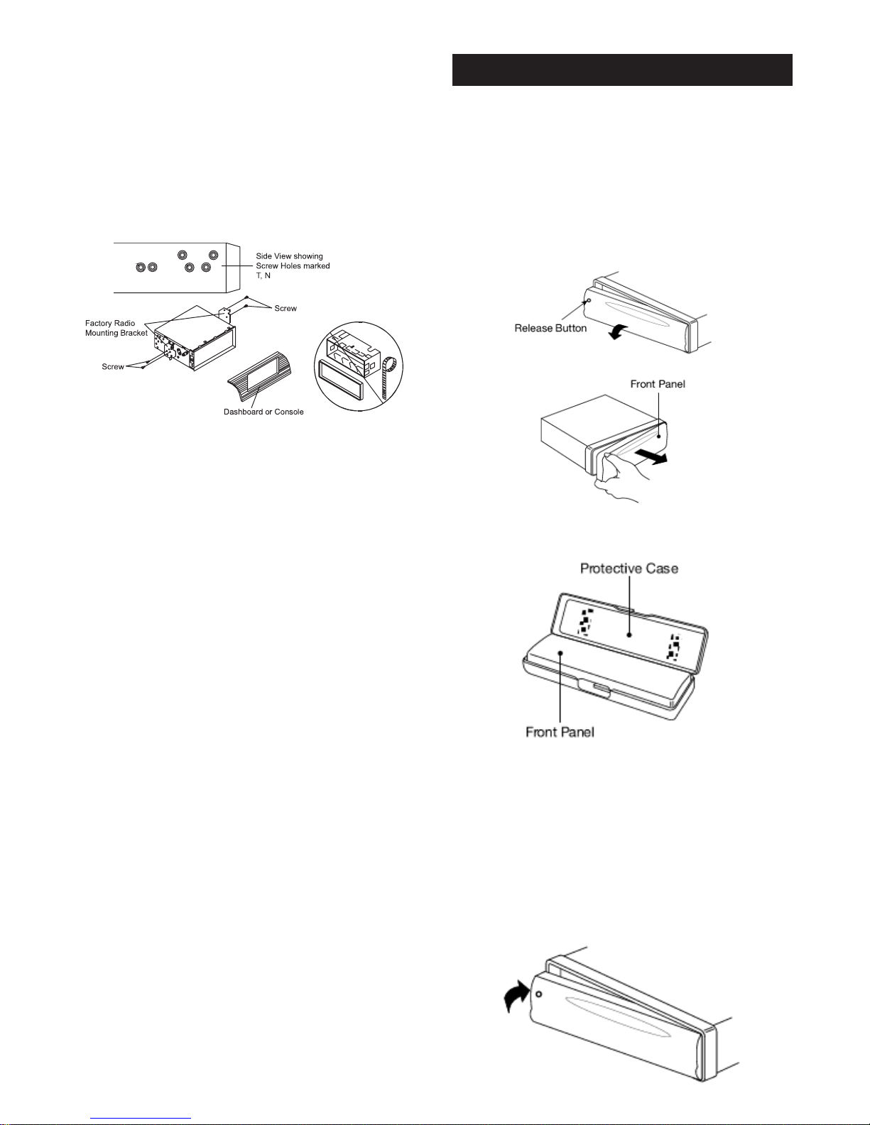
FACEPLATE RELEASE
Press button (7) to detach the
removable faceplate.
SOUND ADJUSTMENT
Press the SEL button (1) shortly to select
the desired adjustment mode. The
adjustment mode will change in the
following order:
VOL BAS TRB BAL FAD
(Volume) (Bass) (Treble) (Balance) (Fader)
By rotating the volume knob (1) clockwise or
counter-clockwise, it is possible to adjust the
desired sound quality.
SYSTEM SETTING
Press and hold the SEL button (1) on the
front panel to enter system setting mode.
Then shortly press the SEL button (1) to
select the item you want to change and
rotate the volume knob (1) to change the
corresponding setting.
1) BEEP ON/OFF
Use the volume knob (1) to set Beep
sound ON or OFF.
2) AREA EUR/USA/ASI/S-A/JPN/OIR
In radio mode, Use the volume knob
(1) to set the different area frequency
spacing.
3) DIM HIGH/LOW/MID
In this menu, rotate the volume knob (3)
to change the brightness of the backlight
among High, Low and Middle.
4) TA ALARM/SEEK
Use the volume knob (1) to set TA
ALARM or TA SEEK.
Traffic announcements
TA SEEK: With activated TA
function the unit searches for a
station with traffic announcements.
TA ALARM: No automatic station
search. The unit sounds a beep
tone if no traffic information is received and
NO TP/TA is displayed. SEEK PI is
displayed if the selected station does not
transmit an RDS signal.
5) PI SOUND/MUTE
Use the volume knob (1) to set PI
SOUND or PI MUTE.
Moving into an area where two stations
with identical AF, but different Pl code
(PI = program information) are
received destabilizes reception. In this
situation you have two options:
PI SOUND: To change stations the
other station is played for less than
one second.
PI MUTE: The other station is
muted.
6) RETUNE L/S
Use the volume knob (1) to set
RETUNE L or RETUNE S.
Delay for automatic search with traffic
announcements and/or program
information:
S (short) after approx. 30 seconds;
L (long) after approx. 90 seconds.
7) MASK DPI/ALL
Use the volume knob (1) to set
MASK DPI or MASK ALL.
Setting to mask station during
search:
DPI : Alternative frequencies with
different Pl code are excluded
from the search.
ALL : Alternative frequencies with
different Pl code and no RDS
information with high signal level
are excluded from the search.
8) TA DX/LOCAL
Use the volume knob (1) to set TA
DX or LOCAL.