3
1. Lay out and identify the three different lengths of post. These can be
identified from the table of contents.
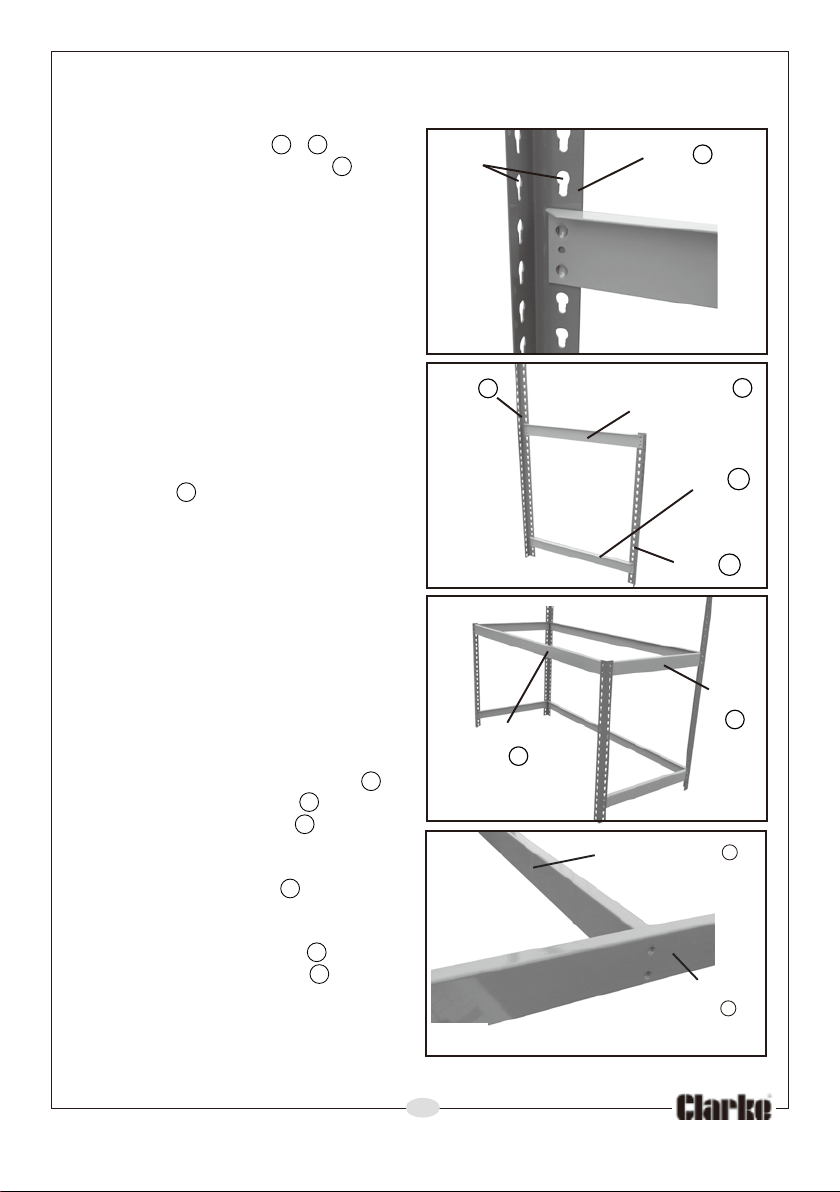
2. Connect the post B & C together
using an mid end beam J as
shown in Fig 1 & Fig 2.
•When using a hammer or mallet,
always strike the edge closest to
the post and protect the paint
with a cloth.
•Only use the mallet to tap gently,
ensuring the tabs of the support
pieces are in line with the slots in
the posts.
3. Decide how high you want the
lower shelf to be, relative to the
floor, and connect a lower end
beam K to complete an end
frame assembly as shown
in Fig 2.
Note that the lower shelf should
be less than half distance from
floor to large shelf for optimum
stability.
4. Repeat this again for the other
end assembly, making sure that
the corresponding lower end
support is at the same height.
Note that the edge with the wider
flange should be installed
uppermost to touch the shelf and that the face with open edges should
face the rear of the unit.
FIG 4
FIG 1
Post B
Slots
Post B Mid End Beam J
FIG 2
Lower End
Beam K
Post C
FIG 3
G
J
Mid End
Beam
Front
Long
6. Fit the centre support F between
the lower end beams K
as in Fig 4.
5. Now fit the front long beam G
and rear long beam G to match
the mid end beams J , thereby
joining the two end frame
assemblies together as in Fig 3.
Add a long beam H at the rear
to support the lower shelf.
Beam
Lower
Centre Support
End
Beam K
F