IMPORTANT
Failure to follow these precautions
could result in personal injury, and/or
damage to property.
1. ALWAYS wear approved impact resistant
safety goggles. (Eye glasses are NOT
safety glasses).
2. ALWAYS wear face or dust mask (where
dust is created), and ear defenders when
necessary.
3. ALWAYS disconnect the tool when not in
use, before changing accessories and
before carrying out any maintenance
4. ALWAYS have trigger in the OFF position
when connecting to an air supply.
5. ALWAYS keep a safe distance between
yourself and other people when using the
tool.
6. Maintain the tool with care. Keep it clean
for best and safest performance.
7. DO NOT wear ill fitting clothing, remove
watches and rings.
8. Quick change couplings should not be
located at the tool. They add weight and
could fail due to vibration.
9. DO NOT over-reach. Keep your proper
footing and balance at all times.
10. DO NOT force or misuse the tool. It will do
a better and safer job at the rate for which
it was designed.
11. DO NOT abuse hoses or connectors.
NEVER carry a tool by the hose, or yank it
to disconnect from the air supply. Keep
hoses away from heat, oil and sharp
edges. Check hoses for weak or worn
condition before use, and ensure that all
connections are secure.
12. DO NOT exceed 90 PSI at the tool.
13. DO NOT modify the tool in any way.
SAFETY PRECAUTIONS for AIR TOOLS
AIR SUPPLY
Tools of this type, operate on a wide range of
air pressures.
It is recommended that air pressure to this tool
does not exceed 90 PSI, at the tool when
running. Higher pressure and unclean air, will
shorten the tools’ life because of faster wear,
and could be a safety hazard.
Water in the air line will cause damage to the
tool. Ensure the tool is properly maintained at
all times. (See maintenance section) The
recommended procedure for connecting this
tools is shown at fig. 1.
The air inlet used for connecting the air supply,
has a 1/8" BSP thread.
Line pressure, or hose inside diameter, should be
increased to compensate for unusually long air
hoses (over 25 feet). Minimum hose diameter
should be 5/16" (8mm) ID., and fittings should
have the same inside dimensions.
OPERATION
Ensure the appropriate bit is pushed firmly
home, until it clicks into place in the drive. With
the air line attached and a pressure regulated
at 90 psi , depress the operating lever.
Forward and reverse is obtained by setting
the Reverse Valve (item 18) located
diagonally opposite the lever.
Pushing the valve ‘in’ against spring pressure,
and turning it anticlockwise to lock in that
position, will select forward or ‘screwing in’
mode. Turning the valve clockwise, allowing
it to spring ‘out’, and remain in that position,
will select reverse.
Three torque ranges are possible with this tool.
Two additional springs are provided, giving a
higher or lower range than that set during
manufacture. To change to a different range,
proceed as follows:
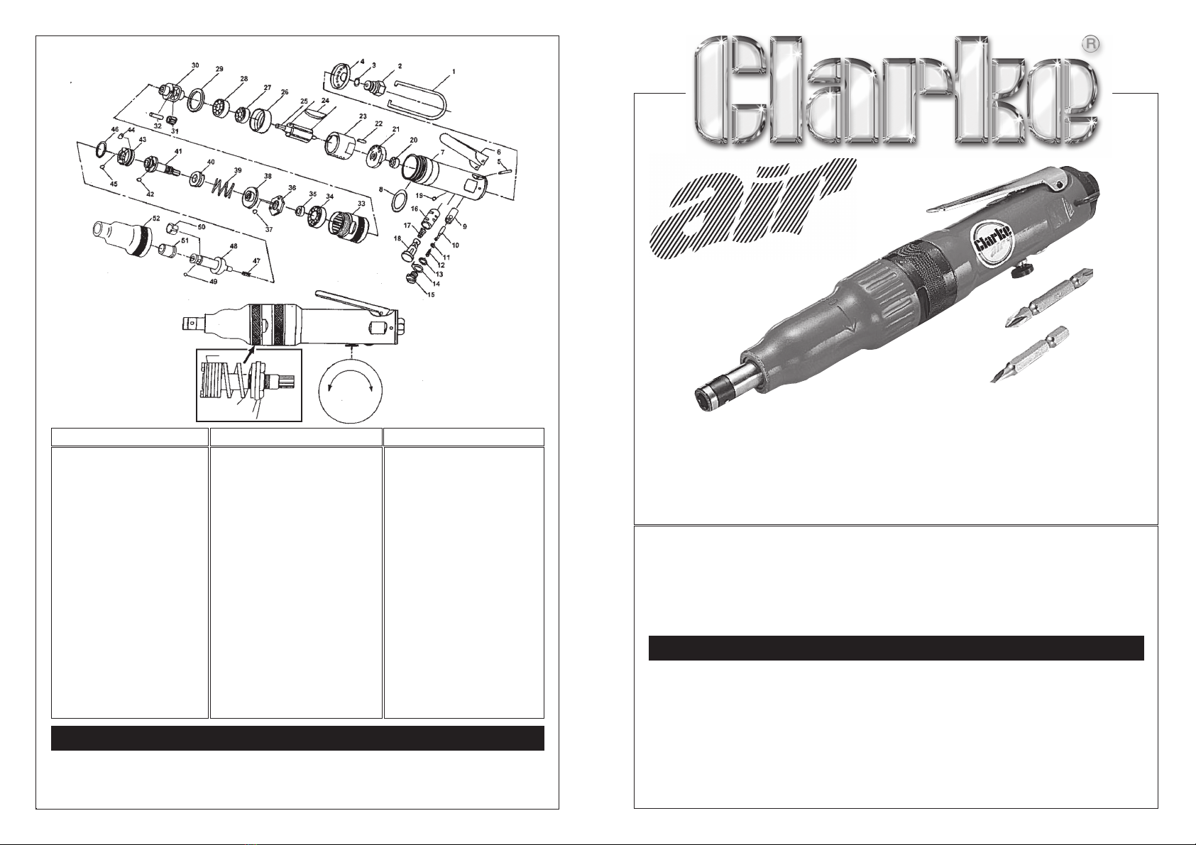
Refer to Parts Diagram inset
1. Unscrew the Clutch case (item 52) noting
that it has a left hand thread.
2. Pull the clutch assembly from the motor
taking care not to lose the collar on the
splined shaft.
3. Holding the splined shaft with the
appropriate wrench (supplied), turn the
top adjuster nut, and remove completely,
allowing the bottom adjuster and control
spring also to be removed.
4. Replace the spring with the one of your
choice, and re-assemble in reverse order.
5. Spring Tension and hence torque applied
to the bit, is increased by turning the top
adjuster clockwise.
MAINTENANCE
Daily
1. Before use, drain water from air tank, air
line and compressor.
2. If no line Lubricator is used, ensure that oil
is applied to the tool (see below).
Weekly
Clean the air inlet filter screen (within item 2).
Periodically
Remover the clutch case (item 52) and clean
and dry the clutch assembly.
Apply a little grease to the clutch assembly,
and into the clutch case to lubricate the
bearings in the nose.
For lubricating the air motor, an air line
lubricator should be used, with SAE 10 oil, (see
fig. 1) adjusted to 2 drops per minute.
If this is not possible, run a few drops of oil
through the tool as required. It may be
entered into the tool air inlet, (ensuring the
strainer is clear), or into the hose at the nearest
connection to the air supply. Then run the tool.
A rust inhibitive oil, available from auto supply
stores etc., is acceptable.
Be aware that factors other than the tool may
effect its operation and efficiency, such as
reduced compressor output, excessive drain
on the airline, moisture or restrictions in the line,
or the use of connectors of improper size or
poor condition which will reduce air supply.
Grit or gum deposits in the tool may also
reduce efficiency. This condition can be
corrected by cleaning the air strainer and
flushing out the tool with gum solvent oil, or
an equal mixture of SAE 10 oil and kerosene.
SPECIFICATIONS
Bit Size ............................... 1/4" Hex
Free Speed ...................... 1,600 RPM
Torque Range .................. 0 - 25 lbs in
Air Inlet .............................. 1/8" BSP
Min. Hose Size (ID) .......... 5/16" (8mm) ID
Ave. Air Consumption .... 4 CFM
Air Pressure Max. ............. 90 PSI
Vibration Level ................ > 2.5m/s2
Net Weight ....................... 0.6 kg
For Spare Parts and Service, please contact your nearest dealer,
or CLARKE International, on one of the following numbers.
PARTS & SERVICE TEL: 020 8988 7400
or e-mail as follows:
PARTS AND SERVICE CONTACTS
FIG. 1