Classeq CST 100 User manual

FITTING INSTRUCTIONS DRYER UNIT
Drawn up: 07/09/2015
Document number : 30011288
Page 1 of 21
Revision: A
Fitting dryer unit to CST unit

FITTING INSTRUCTIONS DRYER UNIT
Drawn up: 07/09/2015
Document number : 30011288
Page 2 of 21
Revision: A

FITTING INSTRUCTIONS DRYER UNIT
Drawn up: 07/09/2015
Document number : 30011288
Page 3 of 21
Revision: A
Contents
1. Introduction................................................................................................................................. 4
2. Recommended Tool Kit.............................................................................................................. 5
3. In this kit...................................................................................................................................... 6
4. Before fitting................................................................................................................................ 7
5. Warning and safety information.................................................................................................. 7
6. Changing direction of unit........................................................................................................... 8
7. Installing dyer controls to machine ........................................................................................... 10
8. Preparing the machine.............................................................................................................. 13
9. Preparing the dryer unit............................................................................................................ 15
10. Fitting the dryer unit.................................................................................................................. 16
11. Wiring the dryer unit.................................................................................................................. 19
12. Testing the unit......................................................................................................................... 20

FITTING INSTRUCTIONS DRYER UNIT
Drawn up: 07/09/2015
Document number : 30011288
Page 4 of 21
Revision: A
1.Introduction
Installation:
Installation should only be carried out by a Classeq approved technician, in accordance with current
regulations and within our instructions.
Each section of this instruction is important in achieving a good installation of the dryer unit. DO NOT
skip any sections.
Familiarise yourself with ALL the instructions before attempting the fitting.
Repairs and spare parts:
The appliance must only be repaired by a Classeq approved technician, using genuine Classeq
spare parts, failure to do so could invalidate any warranty and relieve the manufacture of all liability.
Modification:
Classeq reserves the right to modify either the appliance or the contents of these instructions without
notice.
CAREFULLY READ THESE INSTRUCTIONS, BEFORE INSTALLING THIS APPLIANCE.
INCORRECT INSTALLATION, ADAPTATIONS OR ALTERATIONS COULD RESULT IN INJURY OR
DAMAGE TO PROPERTY.
MALICIOUS DAMAGE, DAMAGE DUE TO NEGLIGENCE, OR FAILURE TO COMPLY WITH THESE
INSTRUCTIONS AND LOCAL LEGISALTION, OR UNAUTHORISED TAMPERING WILL INVALIDATE
ANY WARRANTY AND RELIEVE THE MANUFACTURER OF ALL LIABILITY
FITTING INSTRUCTIONS DRYER UNIT
Drawn up: 07/09/2015
Document number : 30011288
Page 5 of 21
Revision: A
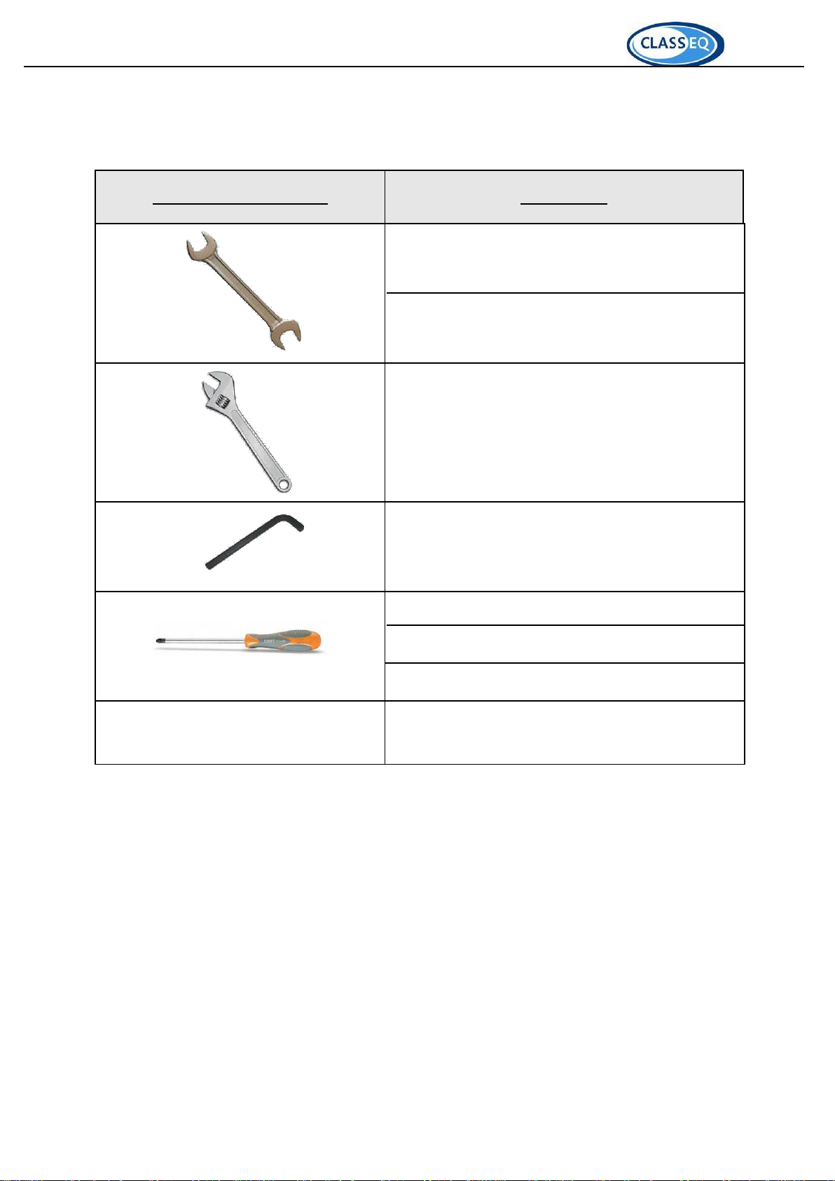
2.Recommended Tool Kit
Recommended hand tools
Specification
8.0mm - Spanner & nut runner / socket
10.0mm - Spanner / nut runner / socket
10mm to 18mm - Adjustable spanner
3mm Hex key
No. 2 - Pozi screw driver
Electric screw driver (small)
Med flat screwdriver
Silicone gun with sealant (MS930 preferred)

FITTING INSTRUCTIONS DRYER UNIT
Drawn up: 07/09/2015
Document number : 30011288
Page 6 of 21
Revision: A
3.In this kit
Picture
Description
Qty
Dryer unit
1
Side brace plate (3 holes)
4
Top brace plate (5 holes)
2
Cassette
1
Cassette link plate
2
Clamping plate (on unit)
2
Seal (on unit)
2
Offset
2

FITTING INSTRUCTIONS DRYER UNIT
Drawn up: 07/09/2015
Document number : 30011288
Page 7 of 21
Revision: A
M5x16mm screws
2
M5x12mm socket button
head scerws
8
M5 flange nut
2
M3 flange nut
2
M5x10mm socket counter
sunk head screw
8
M5 prevailing torque nut
8
M6 Washer
8
Dryer harness lower section
1
Edge protection (**mm)
1
120x2.5mm cable ties
25
4.Before fitting.
Before fitting the dryer unit to the machine ensure that:
The unit is setup for the correct machine direction (i.e. Left hand or right hand exit) and alter
this as required (6).
There is sufficient space for the unit to be installed.
Be sure to peal back any laser film on the side of the machine on which the unit is to be
installed.
5.Warning and safety information
The unit should only be operated at or within the voltage specified on the rating plate on the main
machine. The installer and user are responsible for ensuring the installation and operation of this
machine are in accordance with local and national regulations.
Do not insert any items or parts of your body between moving components, as this could cause injury.
Beware of touching or placing items onto the wash tunnel of the machine, as this can get hot during use.
The dryer unit weighs more than 50kg and should be handled with care. When installing the unit a lifting
trolley should be used.

FITTING INSTRUCTIONS DRYER UNIT
Drawn up: 07/09/2015
Document number : 30011288
Page 8 of 21
Revision: A
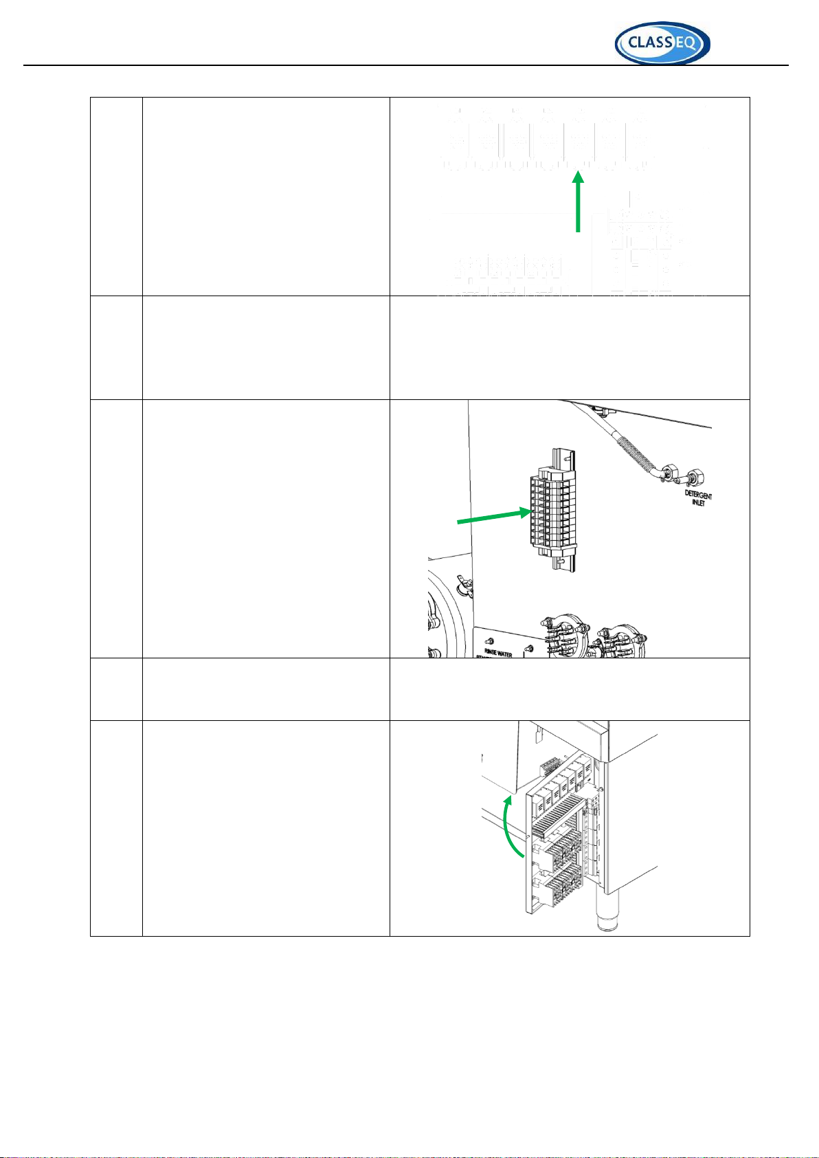
6.Changing direction of unit
Images show changing a unit for a left hand entry machine to a right hand entry unit.
Step
Description
Picture
1
Remove the front and back covers on
the unit
2
Open the blower termimal block case
3
Remove the blower terminal block
case, adjustable thermostat and stud
mounted cable tie.
4
Feed items from step 3 and the main
trunk of the harness through the top
of the unit to the opposite side.
5
Fit the adjustable thermostat to the
themostat bracket, taking care not to
change the temperature setting.

FITTING INSTRUCTIONS DRYER UNIT
Drawn up: 07/09/2015
Document number : 30011288
Page 9 of 21
Revision: A
6
Fit the blower terminal block case to
the side of the top panel.
7
Fit the cable tie with the trunk of the
harness to the top panel opposite the
blower terminal block case.
8
Close blower terminal block case.
9
Remove 2x M5x12mm socket button
head screws from the skirt currently at
the front of the unit.
10
Refit and fasten the front and rear
covers

FITTING INSTRUCTIONS DRYER UNIT
Drawn up: 07/09/2015
Document number : 30011288
Page 10 of 21
Revision: A
11
Refit 2x M5x12mm socket button
head screws to the skirt now at the
front of the unit (without the rear
panel).
7.Installing dyer controls to machine
N.B. Always ensure the machine is isolated from the mains electrical supply before attempting
to fit these components.
Step
Description
Picture
1
Remove the bottom front panel of the
machine
2
Open the control panel box

FITTING INSTRUCTIONS DRYER UNIT
Drawn up: 07/09/2015
Document number : 30011288
Page 11 of 21
Revision: A
3
Fit the dryer unit control panel to the
back using the 2x M5 flange nuts
provided
4
Insert the cables with the bootlace
terminals into the open terminal in the
main terminal block
Brown to L1
Black to L2
Grey to L3
5
Route the white and blue wires with
male terminals into the front of the
control panel.
FITTING INSTRUCTIONS DRYER UNIT
Drawn up: 07/09/2015
Document number : 30011288
Page 12 of 21
Revision: A
6
Locate RL5 (drive motor relay)
7
Remove the wires with the green
insulators from the coil and replace
them with the new wires.
Fit the wires from the machine
harness in the male terminals
8
Fit the dryer harness terminal block to
the front of the wash tank and fasten
using the 2x M3 flange nuts provided
9
Route dryer harness along the
machine harness and cable tie in
place.
10
Close the control panel
DO NOT refit the front panel
DO NOT turn on power to the
machine.
FITTING INSTRUCTIONS DRYER UNIT
Drawn up: 07/09/2015
Document number : 30011288
Page 13 of 21
Revision: A
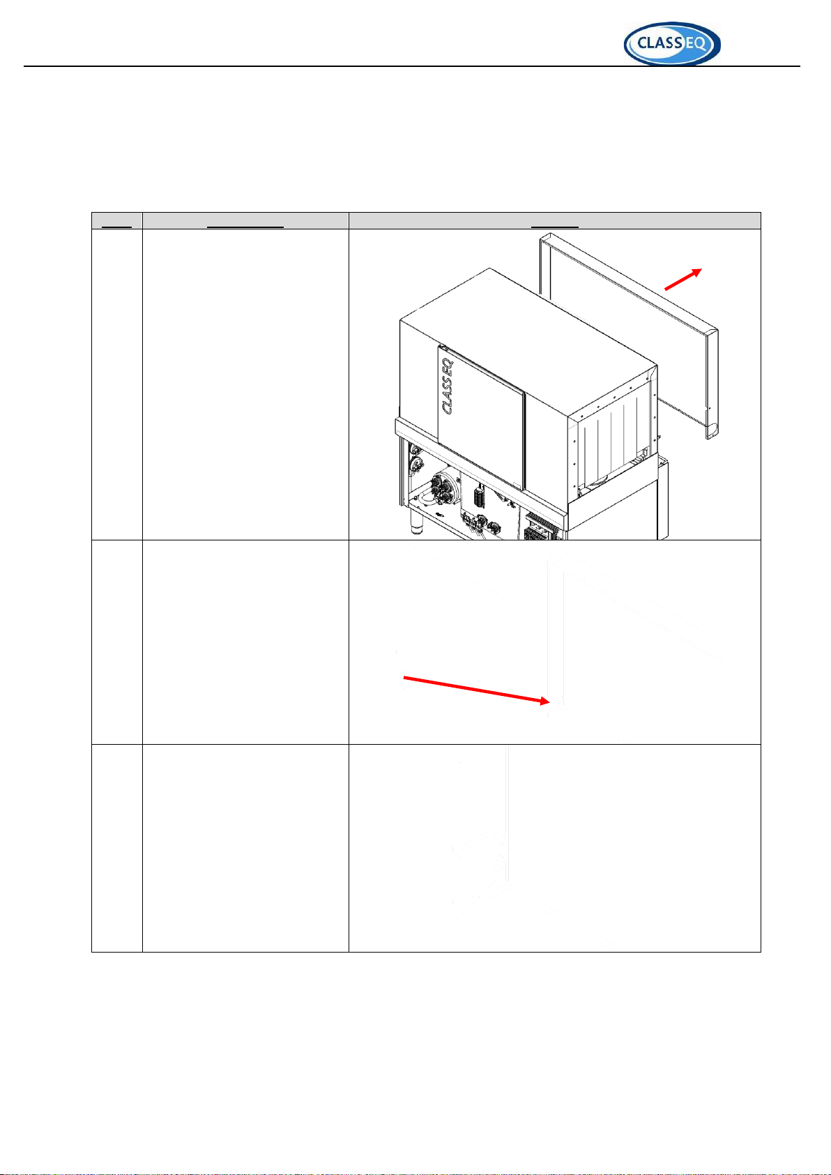
8.Preparing the machine
The following steps should be carried out on the exit side of the machine in order to prepare it for the
installation of the dryer unit.
Images shown are of a machine with a left hand exit.
Step
Description
Picture
1
Remove top rear panel from
machine
2
Remove the “knockout”
section in the rear panel on
the side that will have the
dryer fitted.
2
Fit the edge protection strip
around the exposed edge
FITTING INSTRUCTIONS DRYER UNIT
Drawn up: 07/09/2015
Document number : 30011288
Page 14 of 21
Revision: A
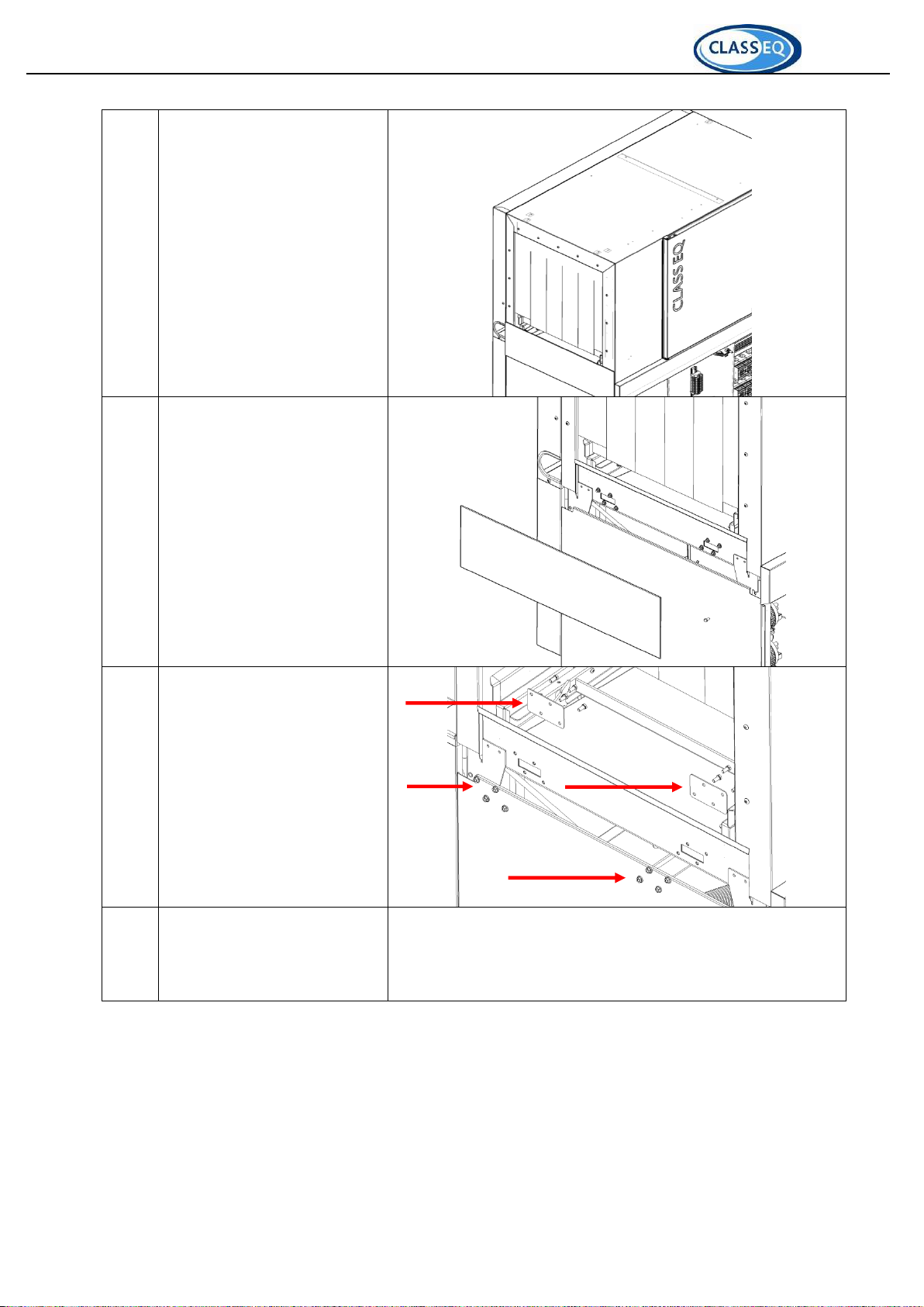
3
Refit the top rear panel
4
Remove the side skirt and hex
head screws from the machine
on the side that will have the
dryer fitted.
5
Remove the cover plate and
seals from the drain holes in
the tank of the machine on the
side that will have the dryer
fitted.
6
Peal back the laser film to
expose steel on the side of the
machine on the side that will
have the dryer fitted.
FITTING INSTRUCTIONS DRYER UNIT
Drawn up: 07/09/2015
Document number : 30011288
Page 15 of 21
Revision: A
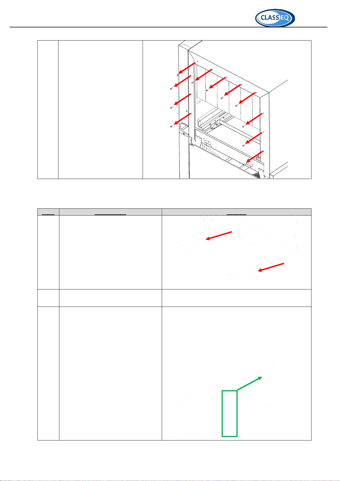
7
Remove and retain 11x
M5x12mm socket button head
screws and flange nuts on the
side that will have the dryer
fitted.
These will be used later to
fasten the unit in place.
9.Preparing the dryer unit
Step
Description
Picture
1
Remove and retain the clamping
plates
2
Peal back all laser film on the mating
face to expose steelwork.
3
Fit the cassette link plates to the dryer
cassette and fasten in place with 4 x
M5x10mm socket counter sunk head
screw, M6 washers and M5 prevailing
torque nut.
Take note of washer placement

FITTING INSTRUCTIONS DRYER UNIT
Drawn up: 07/09/2015
Document number : 30011288
Page 16 of 21
Revision: A
10. Fitting the dryer unit
Images shown are of a machine with a left hand exit unless stated otherwise.
Step
Description
Picture
1
Using a lifting trolley bring the unit
to the exit of the machine so that
the tunnels allign.
DO NOT marry them up yet.
2
Put the dryer harness through the
hole in the rear panel of the
machine.
3
Add sealant to the machine face so
as to create a seal when the unit is
fitted.

FITTING INSTRUCTIONS DRYER UNIT
Drawn up: 07/09/2015
Document number : 30011288
Page 17 of 21
Revision: A
4
Bring the dryer unit towards the
machine and hook the lip on the
sump of the dryer onto the edge of
the machine.
5
Lift the dryer unit into place so that
both units meet, the dryer unit
should lock into place in the
machine.
This is designed as a push fit and
will lock the dryer to the machine.
N.B. Once the unit is locked in
place it cannot be removed.
6
Fit one of the top brace plates to
either side of the mated faces and
fasten into place with the M5x12mm
socket button head screws and
flange nuts removed in 8.7

FITTING INSTRUCTIONS DRYER UNIT
Drawn up: 07/09/2015
Document number : 30011288
Page 18 of 21
Revision: A
7
Fit one of the side brace plates to
either side of the mated faces
toward the front of the unit and
fasten into place with the M5x12mm
socket button head screws and
flange nuts removed in 8.7
8
Repeat step 7 on the rear mated
faces.
9
Ensure the seals line up to the drain
holes.
Fasten the clamping plates into
place over the seals inside the
machine using the M5x12mm
socket button head screws.
10
Align the offsets to the holes in the
base of the machine and fasten in
place with the M5x20 screws

FITTING INSTRUCTIONS DRYER UNIT
Drawn up: 07/09/2015
Document number : 30011288
Page 19 of 21
Revision: A
11
Align the dryer cassette and link
brackets with the machine cassette
and fasten in place with M5x10mm
socket counter sunk head screw
and M5 prevailing torque nut.
12
Pull the harness through to the front
of the machine using the route
shown.
Dress it to the machine harness
using the cable ties where possible.
11. Wiring the dryer unit
The dryer unit harness should be wired into the dryer unit terminal block as shown.
Earth 1.5mm
Black 0.5mm
Orange 0.5mm
White 0.5mm
Grey 0.75mm
Black 0.75mm
Brown 0.75mm
White 1.5mm
Purple 1.5mm
Brown 1.5mm

FITTING INSTRUCTIONS DRYER UNIT
Drawn up: 07/09/2015
Document number : 30011288
Page 20 of 21
Revision: A
12. Testing the unit
Step
Description
Picture
1
Follow commisioning instructions for
the machine as outlined in the
installation and operation manual
supplied.
2
Allow machine to fill and heat.
3
Isolate the machine and open the
control panel
4
Turn on the dryer unit breaker (CB6)
5
Close the control panel
6
Refit the bottom front panel to the
machine.
7
Turn on power to the machine
Other manuals for CST 100
1
Table of contents
Popular Dryer manuals by other brands

Maytag
Maytag MDE17MNAZW0 installation instructions

Maytag
Maytag W10099060 Use and care guide

Midea
Midea MDV160-V02A2/F01-US1305 Service manual

STIEBEL ELTRON
STIEBEL ELTRON GALAXY 1 Installation and operating instructions

Frigidaire
Frigidaire GLGR104FSS2 operating instructions

Bosch
Bosch WT47UHE9DN Installation and operating instructions


