Claymarc A-lign Fencing User manual

A-lign Fencing
12 easy steps
Classic. Elegant. Simple.

All components are manufactured
from clear exterior treated finger-
jointed radiata pine and are machine
primed and undercoated with a two-
coat oil based coating system.
After assembly finish the paint
system with a minimum of two
premium exterior acrylic top coats
with LRV 45+. Alternatively paint
each component form separately
before the fence is erected. This
eliminates cutting in if two or more
finished colours are used. (See
claymark.co.nz for further detail on
painting)
Components (overview)
Bottom Rail
Bottom Rail Infill Bead
or
200mm or 150mm Scribers
112mm or 132mm Posts Metal Angle Bracket
Top Rail
154mm or 179mm Post Cap
200mm Profiled Fence Boards
150mm Profiled Fence Boards
200mm or 150mm
Centre Scriber
Notes:
All fence components available in
5.4m lengths on request.
All cut ends should be primed
and sealed.
36x18mm H3 treated scribers in
1560mm lengths for 200mm profiled
fence boards or 1570mm lengths for
150mm profiled fence boards.
112x112mm or 132x132mm
H4 treated laminated posts in
2.7m lengths.
40x40x40x3mm galvanized
metal angle bracket.
88x42mm H4 treated grooved
bottom rail in 2.7m lengths.
18x6mm H4 treated infill locator
bead in 2.7m lengths.
42x36mm centre scribers in 1560mm lengths
for 200mm profiled fence boards or 1570mm
lengths for 150mm profiled fence boards.
Ex. 150mm wide (110mm cover) H3 treated
profiled fence boards in 2.7m lengths.
Ex. 200mm wide (155mm cover) H3 treated
profiled fence boards in 2.7m lengths.
154x154mm or 179x179mm bevelled post cap
for 112mm or 132mm post.
88x42 H4 treated grooved
top rail in 2.7m lengths.

Other components:
A. 10 gauge 40mm stainless raised head screws
(allow 50 per fence segment)
B. 8 gauge 75mm counter sink screws
(allow 10 per fence segment)
C. Timber adhesive
D. Premium exterior acrylic paint and brush
E. Square, measuring tape and pencil
F. 20mm panel pins
G. Metal angle brackets (two per fence segment)
H. Stringline
I. Woodfiller and trowel
J. Jenkin end seal primer (used for all cut ends)
K. Sandpaper and block
Tools:
L. Post hole borer (300mm diameter) Optional
M. Handsaw or circular saw
N. Drill
O. Drill bits (3&4mm diameter), screwdriver bit
P. Digging equipment
Q. Hammer or Nail gun
R. Spirit level or laser level
S. Easy set concrete
T. A cold beer to appreciate your new fence
Along with the components
shown in the diagram above
you will need the following:
What you will need
K
G
H
I
A
B
C
L
M
N
O
P
Q
R
S
T
J
F
D
E

Plan: the fencing project on
graph paper before proceeding.
Check that the fence lines are
correctly positioned in relation to
the boundary and/or survey pegs.
Ensure the fence and fence height
conform to local council bylaws and
subdivision covenants.
Before digging post holes:
Locate underground services such
as power, gas, telephone, water and
drainage to ensure a safe separation
distance from excavated holes.
Planning sketch and dimensions
1

Setout: Peg out, excavate and
concrete-in a post at either end of
the fence line. Ensure posts are
accurately positioned and plumb as
these determine the accuracy of
the fence line.
Intermediate Posts: Measure and
install intermediate posts up to the
maximum centre span of 2.7m.
Horizontal and vertical alignment
can be achieved by a laser or string
line and level or plumb bob. Posts
should be plumb and secure
before proceeding. Post should
be plumb and secure before
proceeding.
Installing the Posts
2
112x112mm or 132x132mm
H4 laminated posts
Note: For recommended post depths,
relating to area wind speed, refer to
‘foundation detail’ in the table below.
Post depth
600 - 800mm
Post depth
700mm - 1m
1.8m
0.9m
1.2m
1.5m
300
300
Setout: Peg out, excavate and
concrete-in a post at either end of
the fence line. Ensure posts are
accurately positioned and plumb as
these determine the accuracy of
the fence line.
Intermediate Posts: Measure and
install intermediate posts up to the
maximum centre span of 2.7m.
Horizontal and vertical alignment
can be achieved by a laser or string
line and level or plumb bob. Posts
should be plumb and secure
before proceeding.
Post should be plumb and secure
before proceeding.
Installing the Posts
2
112x112mm or 132x132mm
H4 laminated posts
Note: For recommended post depths,
relating to area wind speed, refer to
‘foundation detail’ in the table below.
Post depth
600 - 800mm
Post depth
700mm - 1m
1.8m
0.9m
1.2m
1.5m
300
300
Post size
mm
Maximum
Post Centres Windzone
For Fence heights
0. 9-1 .2 m 1.5 m 1.8m
Embeded depth for fence posts
High 600mm 700mm -------
112 x 11 2 2.7m Extra high 700mm 800mm -------
Brisbane 800mm 800mm -------
High ------- ------- 700mm
112 x 11 2 1.8m Extra high ------- ------- 800mm
Brisbane ------- ------- 800mm
High ------- ------- 800mm
132x132 2.7m Extra high ------- ------- 900mm
Brisbane ------- ------- 1000mm
Post size
mm
Maximum
Post
Centres
Windzone
For Fence heights
0.9-1.2m 1.5m 1.8m
Embeded depth for fence posts
High 600mm 700mm -------
112 x112 2.7m Extra high 700mm 800mm -------
Brisbane 800mm 800mm -------
High ------- ------- 700mm
112 x112 1.8m Extra high ------- ------- 800mm
Brisbane ------- ------- 800mm
High ------- ------- 800mm
132x132 2.7m Extra high ------- ------- 900mm
Brisbane ------- ------- 1000mm

Trim the 88x42mm bottom rail
to the required length and fix
the metal angle bracket to the
underside of the rail with 10
gauge (40mm) screws.
Level and fix the bottom rail on
the centre line of the posts by
screw-fixing through the metal
angle bracket into the post.
Use a spirit or laser level to
ensure bottom rail is fixed level
between posts.
Fitting the Bottom Rail & Bracket
3

Where the ground is sloping,
maintain the alignment of the
profiled boards by creating
steps at each panel by one full
board cover width — (110mm)
for 150mm profiled fence
board and (155mm) for 200mm
profiled fence board (fence
board/s).
If the ground slope is severe
it may be necessary to install
a short stub post midway
between posts to split the
levels of the bottom rail.
Dealing with a sloping ground
Cover
width
4

Trim the bottom rail infill bead to
the length of the bottom rail. Fit the
bottom rail infill bead into the centre
groove of the bottom rail (tapered
side up). Avoid excessive bending of
the infill bead to avoid breakage.
Fitting the Bottom Rail Infill Bead
5

Trim the first fence board to fit.
Install only the first fence board
over the infill bead and bottom rail.
This step assists in setting the
scribers in the correct position.
Installing the first Profile Fence Board
6

Measure, trim and locate one set of
36x18mm scribers to the front side
of the fence. Fix scriber to the post
with 10 gauge (40mm) stainless
steel raised head screws at the
top and bottom, and as required
between.
Trim the top of the scribers
5mm below the last step
to allow the top rail recess
to engage and sit flat on the
scriber.
Setting the front Scribers
5mm
gap
7

Trim and stack three more fence
boards to the required height by
fitting into the 36x18mm scriber.
From the rear side, lightly pin
through the top of the fence
board to the scriber. Once set
nail/punch pins flush with the
profiled fence board.
Installing three more Profiled Fence Boards
8

Trim the 42x36mm centre scriber to
match 18mm side scribers already
installed. Install centre scriber on
front side after the fourth fence
board is in place.
Fix centre scriber into every second
rail with 10 gauge (40mm) stainless
steel raised head screws. Install the
remaining fence boards and lightly
pin through the centre of each
board.
Do not secure the centre
scriber to the bottom rail
until step 11.
Setting the front Centre Scribers
9

Trim and locate the rear set of
18mm side scribers to the reverse
side of the fence and secure to
the post as per step 7. Apply hand
pressure to the scriber so it seals
firmly against the fence boards.
Once all scribers are in place,
holding pins (from steps 8 & 9) can
either be removed or nailed off and
punched.
Setting the rear Scribers
10

Trim and install the 42x36mm
centre scriber on the rear side.
Screw fix into every second
fence board.
Fix centre scriber to bottom
rail using 8 gauge (75mm)
countersunk screws. Drill at 45˚
and screw fix centre scriber into
the bottom rail. Seal and fill any
remaining holes as required.
Setting the rear Centre Scribers
11

Trim the top rail and engage the
recess with the top
fence board.
Drill & countersink 45˚ holes
for a clean finish. Screw fix
the top rail at 45˚ into the post
using a pair of 8 gauge (75mm)
countersunk screws at each
end. Fill hole, sand and seal for
a cleaner finish.
If required trim the post to the
desired height.
Apply adhesive to top of post,
then install post cap.
Installing the Top Rail and Post Caps
12
Table of contents
Popular Lawn And Garden Equipment manuals by other brands
FCMP OUTDOOR
FCMP OUTDOOR RM4000 instructions
Texas
Texas Power Cart 120 user manual

Simplicity
Simplicity 4552 Illustrated parts list
Rutland County Garden Furniture
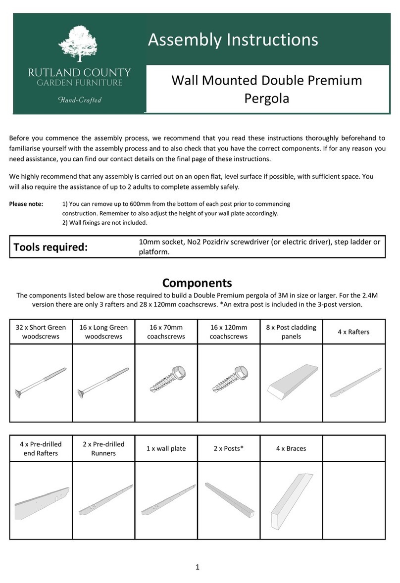
Rutland County Garden Furniture Wall Mounted Double Premium Pergola Assembly instructions
Baroness
Baroness TDA1200 Owner's operating manual

Trac Vac
Trac Vac CV385-PRO Operating and assembly manual
