Baroness TDA1200 Operation manual
・
Serial No. TDA1200: 21038-・ TDA1600: 21026- Original lnstructions Ver. 2.1
Read this manual and the owner's manual for the engine before using the machine.Required reading
Tractor Mounted AeratorTractor Mounted Aerator
Owner's Operating Manual

Greeting.................................................................................................................................. 3
Introduction............................................................................................................................. 3
Warning Symbols............................................................................................................... 3
Precautionary Statement ................................................................................................... 4
Purpose.............................................................................................................................. 4
Safety ..................................................................................................................................... 4
Safe Operating Practices ................................................................................................... 5
Training.......................................................................................................................... 5
Preparation.................................................................................................................... 5
Operation....................................................................................................................... 5
Maintenance and Storage ............................................................................................. 6
Towing ........................................................................................................................... 6
Disposal.................................................................................................................................. 6
Recycle and Waste Disposal ............................................................................................. 6
About Recycle ............................................................................................................... 6
About The Waste Disposal ............................................................................................ 6
Product Overview ................................................................................................................... 7
1. Specications................................................................................................................. 7
1-1. Specications ......................................................................................................... 7
TDA1200 .............................................................................................................. 7
TDA1600 .............................................................................................................. 7
1-2. Types of Tines ........................................................................................................ 8
1-3. Relationship between Operation Speed and Pitch................................................. 9
TDA1200 .............................................................................................................. 9
TDA1600 .............................................................................................................. 9
2.
Names of Each Section................................................................................................ 10
3.
Regulation Decals .........................................................................................................11
3-1. Positions of Regulation Decals .............................................................................11
3-2. Description of Regulation Decals ..........................................................................11
Serial Number Plate ............................................................................................11
Specication Decal..............................................................................................11
UKCA Mark......................................................................................................... 12
Year of Manufacture Decal ................................................................................. 12
4. Safety Signs and Instruction Signs .............................................................................. 13
4-1. About Safety Signs and Instruction Signs ............................................................ 13
4-2. Positions and Description of Safety Decals and Instruction Decals..................... 13
Handling Instructions............................................................................................................ 14
5. Tractor.......................................................................................................................... 14
5-1. Tractor Standards................................................................................................. 14
5-2. Preparation on The Tractor .................................................................................. 14
6. Adjustment before Attachment ..................................................................................... 14
6-1. Precautions about Attachment ............................................................................. 14
6-2. Method of Attaching The Machine........................................................................ 14
6-3. Method of Attaching Universal Joint..................................................................... 15
6-4. Method of Cutting Universal Joint ........................................................................ 17
7.
Inspections ................................................................................................................... 18
7-1. Precautions before Inspection.............................................................................. 18
7-2. Inspection of Covers ............................................................................................ 18
7-3. Inspection of Rollers............................................................................................. 18
7-4. Inspection of Tines ............................................................................................... 18
7-5. Inspection of Lawn Pressing Plate ....................................................................... 18
7-6. Inspection of Gear Oil .......................................................................................... 19
7-7. Supply of Gear Oil................................................................................................ 19
7-8. Inspection of Universal Joint ................................................................................ 19
7-9. Inspection of Oil Leakage..................................................................................... 19
8. Tightening Torques....................................................................................................... 20
8-1. Standard Tightening Torques ............................................................................... 20
8-2. Tightening Torque by Model ................................................................................. 21
TDA1200 ............................................................................................................ 21
TDA1600 ............................................................................................................ 22
9. Adjustment before Operation ....................................................................................... 23
9-1. Precautions about Adjustment ............................................................................. 23
9-2. Adjustment of Tine Depth ..................................................................................... 23
10.
Operation Method ...................................................................................................... 24
10-1. Positions and Description of Operation Decals.................................................. 24
10-2. Change Lever..................................................................................................... 25
Contents
−1−

10-3. Up-Down Handle................................................................................................ 25
10-4. Rear Roller ......................................................................................................... 26
11.
Traveling..................................................................................................................... 26
11-1. Precautions before Traveling.............................................................................. 26
11-2. Traveling Operation ............................................................................................ 26
12. Operations ................................................................................................................. 27
12-1. Precautions before Operation ............................................................................ 27
12-2. Aeration Procedure ............................................................................................ 28
13. Transporting ............................................................................................................... 28
14. Long-Term Storage .................................................................................................... 28
Maintenance......................................................................................................................... 29
15. Maintenance Precautions .......................................................................................... 29
16. Maintenance Schedule .............................................................................................. 29
17. Greasing .................................................................................................................... 30
17-1. About Greasing .................................................................................................. 30
17-2. Greasing Points.................................................................................................. 30
18. Maintenance Work ..................................................................................................... 30
18-1. Cleaning of Aeration Section.............................................................................. 30
18-2. Change of Tines ................................................................................................. 30
18-3. Change of Gear Oil ............................................................................................ 31
18-4. Disassembly of Crank ........................................................................................ 31
Timing Chart....................................................................................................... 32
TDA1200 ............................................................................................................ 32
TDA1600 ............................................................................................................ 33
−2−
Greeting
Thank you for purchasing the Baroness product.
This manual describes the proper handling, adjustment, and inspection of your product.
We hope you will use the product safely, and take advantage of its best performance.
Introduction
Read this manual carefully to ensure that you thoroughly understand how to properly operate
and maintain the product, and to avoid causing injury to yourself or others.
The operator is responsible for operating the product properly and safely.
Maintenance should only be performed by a certified specialist.
If you have any questions concerning maintenance or genuine parts, please contact your
local Baroness dealer or Kyoeisha.
When making inquiries about the product, please specify the product's model designation
and serial number.
When loaning or transferring the product, please also provide this manual together with the
product.
Kyoeisha Co., Ltd.
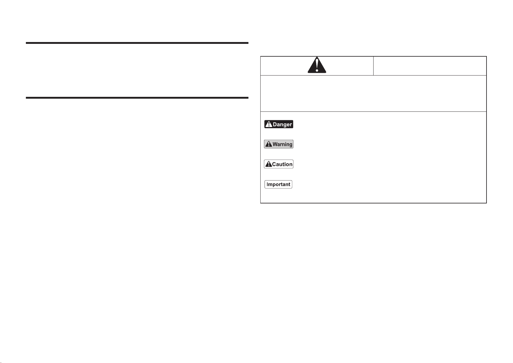
Warning Symbols
This manual uses the following warning symbols for handling precautions that are important
for your safety.
Warning symbol
This symbol indicates the articles regarding “Danger,” “Warning,” or “Caution.”
Those articles describe important safety precautions and so read them carefully to
understand completely before operating the machine.
Failure to adequately follow these safety precautions may cause an accident.
This symbol indicates that serious injury or death will occur if the warning is ignored.
This symbol indicates that serious injury or death may occur if the warning is ignored.
This symbol indicates that injury or damage to property may occur if the warning is ignored.
This symbol indicates precautions on the mechanism of the machine.
−3−

Precautionary Statement
The information described in this manual is subject to change for improvement without
prior notice.
When replacing parts, be sure to use genuine Baroness parts or parts designated by
Kyoeisha.
Note that the Baroness product warranty may not apply to defects caused by the use of
parts from other companies.
Prior to use, carefully read the following manuals to thoroughly understand the contents for
safe and correct operation.
● Baroness Owner's Operating Manual
● The Tractor’s Owner’s Manual
● Service Instructions for PTO Drive Shafts
Purpose
This product is intended for aerating golf courses.
Do not use this product in any way other than its intended purpose, and do not modify this
product.
Operating this product for other purposes and modifying it may be very dangerous and may
cause damage to the product.
Safety
Failure to adequately follow these safety precautions may cause an accident resulting in
injury or death.
This product is designed to ensure safe operation and has been tested and inspected
thoroughly before shipment from the factory.
The product is equipped with safety devices to prevent accidents.
However, whether the product demonstrates its original performance level depends on the
manner in which it is operated and handled, as well as the manner in which it is managed
on a daily basis.
Inappropriate use or management of the product may result in injury or death.
Observe the following safety instructions to ensure safe operation.
−4−

Safe Operating Practices
Training
1.Read this manual and other training material carefully.Be familiar with the controls, safety
signs, and the proper use of the equipment.
2.If the operator or mechanic can not read English it is the owner’s responsibility to explain
this material to them.
3.All operators and mechanics should seek and obtain professional and practical
instruction. The owner is responsible for training the users.
4.Never allow children or people unfamiliar with these instructions to use or service the
machine.
5.The owner/user can prevent and is responsible for accidents or injuries occurring to
themselves ,other people, or property.
6.Keep in mind that the owner, operator, and mechanic are responsible for accidents or
hazards occurring to other people or their property.
7.You can find additional safety information where needed throughout this manual.
Preparation
1.Evaluate the terrain to determine what accessories and attachments are needed to
properly and safely perform the job. Only use accessories and attachments approved by
the manufacturer.
2.Inspect the area where the equipment is to be used and remove all objects such as rocks,
toys and wire which can be thrown by the machine.
3.Keep children out of the operating area and under the watchful care of a responsible adult
other than the operator.
4.Check that shields are attached properly.
5.Before using, always visually inspect to see that the tines and tine mounts are not worn or
damaged.
When some tines are worn, replace all the installed tines at the same time to prevent
abnormal vibration.
6.Pay attention to all the tine mount holders, which operate simultaneously.
Operation
1.Only operate in good light, keeping away from holes and hidden hazards.
2.Never operate the machine with damaged guards, shields, or without safety protective
devices in place.
3.Stop the engine in the following conditions.
[1]Before making depth adjustment.
[2]Before clearing blockages.
[3]Before checking, cleaning or working on the machine.
[4]After striking a foreign object or if an abnormal vibration occurs.
Inspect the machine for damage and make repairs before restarting and operating the
equipment.
4.Keep hands and feet away from the rotating parts.
5.Never operate while people, especially children, or pets are nearby.
6.Stop the tines rotating before crossing surfaces other than grass.
7.Disengage drive to attachments when transporting or not in use.
8.Take care when loading or unloading the machine into a trailer or a truck. Load or unload
the machine in a flat and safe place. Before loading or unloading, set the parking brake
on the truck or trailer, stop the engine, and chock the wheels.
Fasten the machine to the truck with a rope or other suitable restraining device that has
sufficient strength.
−5−

Maintenance and Storage
1.Disengage drives on level ground, stop drive to the tine section, set parking brake, stop
engine. Wait for all movement to stop before adjusting, cleaning or repairing.
2.Never allow untrained personnel to service machine.
3.Appropriately manage and correctly use the tools necessary for servicing or adjusting the
machine.
4.Carefully release pressure from components with stored energy.
5.Use care when checking the tines.
[1]Wrap the tines or wear gloves, and use caution when servicing them.
[2]Only replace tines.
6.On multi-bladed machines, take care as rotating one blade can cause other blades to
rotate.
7.Keep hands and feet away from moving parts. If possible, do not make adjustments with
the engine running.
8.Keep all parts in good working condition and all hardware tightened. Replace all worn or
damaged decals.
9.Keep all nuts, bolts and screws tight to be sure the equipment is in safe working condition.
Towing
1.Follow the manufacturer’s recommendation for weight limits for towed equipment and
towing on slopes.
Disposal
Recycle and Waste Disposal
About Recycle
Recycling battery etc. is recommended for environmental conservation and economical use
of resources.
It may be required by local laws.
About The Waste Disposal
Make sure that waste generated when servicing or repairing the machine is disposed of in
accordance with local regulations.
(e.g. waste oil, antifreeze, rubber products, and wires etc.)
−6−

TDA1600
Model TDA1600
Dimensions
Total length 38.19 in 97 cm
Total width 70.47 in 179 cm
Total height 33.46 in 85 cm
Weight 1278.66 lb 580 kg
Gear oil capacity 1.0 U.S.gals 3.8 dm3(3.8 L)
Number of crank 8
Tine φ17 ・8.46 in φ17・215 mm
Number of tines 24 pcs (Various options available)
Aerating width 61.42 in 156 cm
Pitch (Traveling direction) Depending on the condition
Interval 2.56 / 3.94 in 6.5・10 cm
Working depth Max. 7.09 in
(Depending on the condition)
Max. 18 cm
(Depending on the condition)
Drive Aerating PTO driving
Speed of PTO rotation Max. 1,000 rpm
Working speed -
Applicable
tractor
Horsepower 17.6 kW (24.0 PS) or more
Max lifting
capacity 1,432.98 lbf or more 700 kgf or more
Universal
joint
Clutch setting
torque
Allowed max 4,602.52 lb-in Allowed max
520 N-m (5,302.44 kgf-cm)
Regular use 2478.28 lb-in Regular use
280 N-m (2,855.16 kgf-cm)
Connection Tractor ; 3-point link lifting type
Efficiency 0.77 acres/hour
(1.24 mph x Operating width)
3,120 m2/h
(2.0 km/h x Operating width)
Product Overview
1. Specifications
1-1. Specifications
TDA1200
Model TDA1200
Dimensions
Total length 38.19 in 97 cm
Total width 55.91 in 142 cm
Total height 33.46 in 85 cm
Weight 1157.41 lb 525 kg
Gear oil capacity 1.0 U.S.gals 3.8 dm3(3.8 L)
Number of crank 6
Tine φ17 ・8.46 in φ17・215 mm
Number of tines 18 pcs (Various options available)
Aerating width 46.06 in 117 cm
Pitch (Traveling direction) Depending on the condition
Interval 2.56/3.94 in 6.5・10 cm
Working depth Max. 9.84 in
(Depending on the condition)
Max. 25 cm
(Depending on the condition)
Drive Aerating PTO driving
Speed of PTO rotation Max. 400 rpm
Working speed -
Applicable
tractor
Horsepower 13.2 kW (18.0 PS) or more
Max lifting
capacity 1,432.98 lbf or more 650 kgf or more
Universal
joint
Clutch setting
torque
Allowed max 4,602.52 lb-in Allowed max
520 N-m (5,302.44 kgf-cm)
Regular use 2478.28 lb-in Regular use
280 N-m (2,855.16 kgf-cm)
Connection Tractor ; 3-point link lifting type
Efficiency 0.46 acres/hour
(0.99 mph x Operating width)
1,872 m2/h
(1.6 km/h x Operating width)
−7−

1-2. Types of Tines
There are two main types of tines: "pipe type" (which pulls out the lawn) and "spike type"
(which drills holes).
Pipe type Spike type
Aeration effect Large effect Good
Permeability effect Large effect Good
Underground gas diffusion effect Large effect Good
Damage to turf surface Large Less than with pipe type
Damage to lawn Large Less than with pipe type
Lawn recovery Takes time Quick
Aeration period When lawn cultivation is
thriving
Whenever needed
Core disposal Necessary Unnecessary
(Cores not discharged)
Mowing after aeration Better to mow Better to mow
Effect on play after aeration Not immediately possible Instantly possible
(However, mowing after
tamping is required.)
Degradation of thatch by mixing with soil Promoted Limited
1.Pipe-type tines
Tip dimensions Outer
diameter
of mount
Total
length
Quantity
used
Tine
mount
Lawn
pressing
plate
Inner
diameter
Outer
diameter
φ10V tine 100 6 mm
(0.24 in)
9.5 mm
(0.37 in)
100 mm
(3.94 in)
72
96
Specialized Specialized
φ12V tine 120 8.2mm
(0.323 in)
9.5 mm
(0.37 in)
120 mm
(4.72 in)
72
96
Specialized Specialized
φ13V tine 225 7 mm
(0.43 in)
12 mm
(0.47 in)
225 mm
(8.46 in)
18
24 - -
φ16V tine 125 11 mm
(0.43 in)
16 mm
(0.63 in)
125 mm
(4.92 in)
36
48
Specialized
-
φ17V tine 215 10 mm
(0.39 in)
12 mm
(0.47 in)
215 mm
(8.46 in)
18
24 - -
φ17V tine 265 10 mm
(0.39 in)
12 mm
(0.47 in)
265 mm
(10.43 in)
18
24 - -
* In the column “Quantity used”, the upper figure indicates the quantity for TDA1200 and the
lower for TDA1600.
2.Spike-type tines
Tip dimensions Outer
diameter
of mount
Total
length
Quantity
used
Tine
mount
Lawn
pressing
plate
Inner
diameter
Outer
diameter
φ8 spike tine 8 mm
(0.31 in)
16 mm
(0.63 in)
120 mm
(4.72 in)
36
48
Specialized
-
φ10 solid tine 10 mm
(0.39 in)
9.5 mm
(0.37 in)
100 mm
(3.94 in)
72
96
Specialized Specialized
φ12.5 spike tine 12.5 mm
(0.49 in)
16 mm
(0.63 in)
120 mm
(4.72 in)
36
48
Specialized
-
* In the column “Quantity used”, the upper figure indicates the quantity for TDA1200 and the
lower for TDA1600.
−8−

1-3. Relationship between Operation Speed and Pitch
TDA1200
The engine rotation speed during tractor operation should be 1,600 - 2,000 rpm.
Max PTO rotation speed should be 400 rpm.
If the PTO rotation speed exceeds 400 rpm, the machine will be damaged.
Use the following table as reference.
Tractor's speed and the pitch vary depending on the tractor's specifications.
Tractor TDA1200
Auxiliary
speed change
Main
speed change Speed PTO rotation Crank rotation Pitch
1 1 0.52 km/h 1st speed
Slow speed 53 mm
High speed 42 mm
1 2 0.75 km/h 1st speed
Slow speed 75 mm
High speed 60 mm
1 3 1.06 km/h 1st speed
Slow speed 108 mm
High speed 86 mm
1 4 1.60 km/h 1st speed
Slow speed 163 mm
High speed 130 mm
* The above table shows the figures during the maximum engine rotation speed 1,800 rpm.
TDA1600
The engine rotation speed during tractor operation should be 1,800 -2,300 rpm.
Max PTO rotation speed should be 1,000 rpm.
If the PTO rotation speed exceeds 1,000 rpm, the machine will be damaged.
Use the following table as reference.
Tractor's speed and the pitch vary depending on the tractor's specifications.
Tractor TDA1600
Auxiliary
speed change
Main
speed change Speed PTO rotation Crank rotation Pitch
1 1 0.58 km/h
1st speed
Slow speed 53 mm
High speed 42 mm
2nd speed
Slow speed 37 mm
High speed 30 mm
1 2 0.83 km/h
1st speed
Slow speed 75 mm
High speed 60 mm
2nd speed
Slow speed 53 mm
High speed 42 mm
1 3 1.18 km/h
1st speed
Slow speed 108 mm
High speed 86 mm
2nd speed
Slow speed 75 mm
High speed 60 mm
3rd speed
Slow speed 50 mm
High speed 40 mm
1 4 1.78 km/h
1st speed
Slow speed 163 mm
High speed 130 mm
2nd speed
Slow speed 114 mm
High speed 91 mm
3rd speed
Slow speed 75 mm
High speed 60 mm
*The above table shows the figures during the maximum engine rotation speed 2,000 rpm.
−9−

Front cover
Up-down handle
Scraper
Protection pipe
Rear roller
Tine mount
Tine
Lawn pressing plate
Roller hanger
Frame
Roller holding fixture
Rear cover
Change lever
Gear box
Front roller
Tine mount holder
2.Names of Each Section
−10−
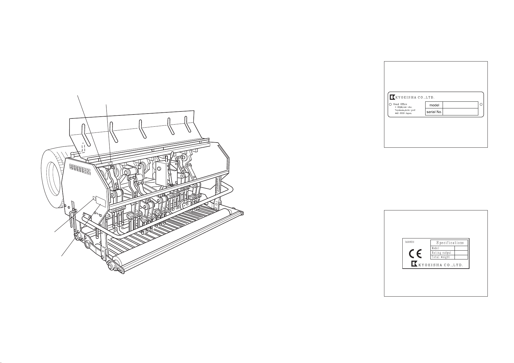
3-2. Description of Regulation Decals
Serial Number Plate
The serial number plate indicates the model and serial number of the machine.
Specification Decal
(For Europe)
CE mark indicates that the machine sold in the EU nations complies with the EU
requirements.
The Specification decal indicates the CE marking, model , and weight, etc.
3.Regulation Decals
3-1. Positions of Regulation Decals
Serial number plate
Year of manufacture decal
Specification decal
UKCA mark
−11−

UKCA Mark
(For UK)
UKCA mark indicates that the machine sold in the UK complies with the UK requirements.
Year of Manufacture Decal
(For Europe)
The year of manufacture decal indicates the year when this machine was manufactured.
YEAR OF
MANUFACTURE
−12−
4. Safety Signs and Instruction Signs
4-1. About Safety Signs and Instruction Signs
Safety decals and instruction decals are attached to this product. Make sure that they are preserved in their entirety. If they are damaged, become dirty, or peel off, replace them with new ones.
Part numbers for decals that need to be replaced are listed in the parts catalog. Order them from a Baroness dealer or Kyoeisha.
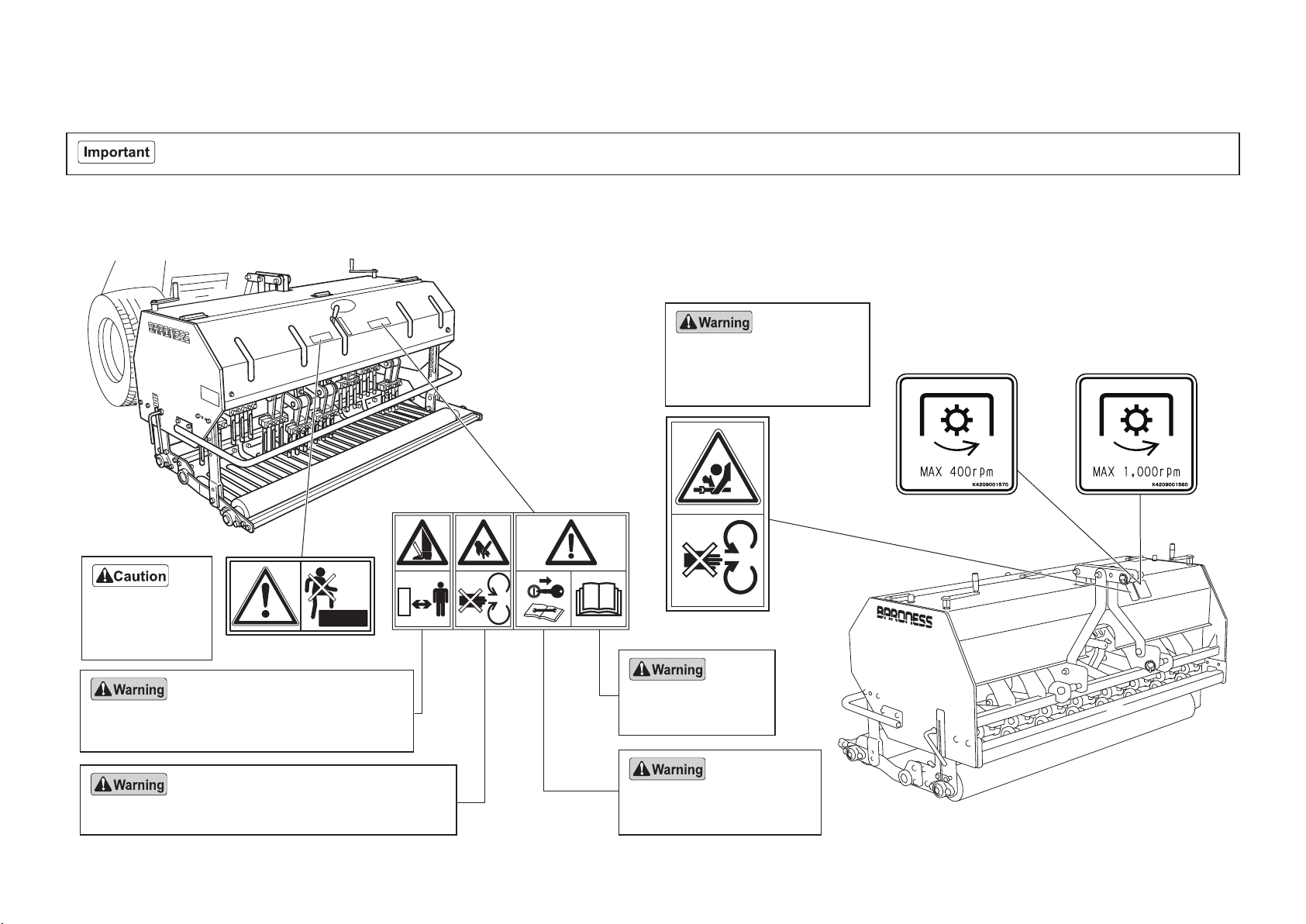
4-2. Positions and Description of Safety Decals and Instruction Decals
K4205002300
K4205001750
K4205001760
K4205001750
Handling precautions
Remove the ignition key
before maintenance work.
May cut your hand - Keep hands away from moving parts.
May cut your leg - Be sure that people around the
machine keep a safe distance away during operation.
Read the Owner's
Operating Manual.
K4205002300
Prohibition of riding decal
>TDA1200@
K4209001570
PTO MAX 400 rpm decal
It indicates PTO max
rotation speed.
>TDA1600@
K4209001560
PTO MAX 1000 rpm decal
It indicates PTO max
rotation speed.
K4205001760
PTO caution decal
May catch your arm -
Keep away from PTO moving
parts during the engine running.
Do not ride
the mechanical
equipment.
−13−
Handling Instructions
5. Tractor
5-1. Tractor Standards
This machine employs “standard three-point link” mounting system. In the “standard three-
point link”, attach the top and lower links of the tractor and the universal joint of this machine
by hand.
5-2. Preparation on The Tractor
Read the “three-point link standards” in the tractor’s owner’s manual carefully.
Only the tractors equipped with standard three-point link parts can be connected to this
machine.
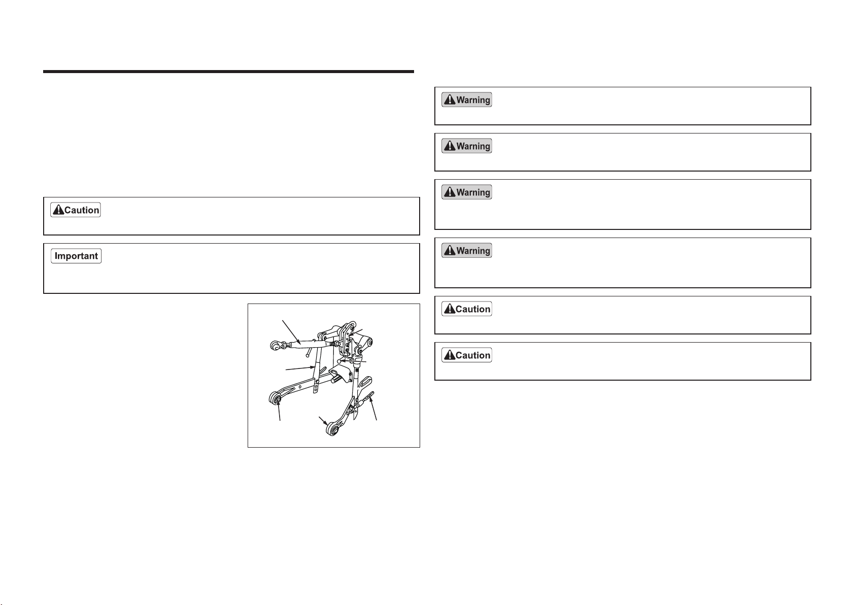
1.If the tractor is equipped with specific three-
point link, remove the top link bracket for
specific three-point link and replace it with
standard three-point link parts.
Use the length-adjustable top link, the both
ends of which have a screw.
Attach the lift rod to the front hole of the
lower link.
2.If the moving distance when raising and
lowering the attached machine is insufficient, adjust it by changing the mounting holes on
the lift rod
● Use the upper hole to increase the moving distance when raising.
● Use the lower hole to increase the moving distance when lowering.
Top link Top link
bracket
Leveling
handle
Turn buckle
Right
lower link
Left lower link
Lift rod
6. Adjustment before Attachment
6-1. Precautions about Attachment
Make sure there is no one around the tractor and between this machine and the tractor.
Do not get under the machine. Do not put your foot under the machine.
Before attaching the machine, apply the parking brake of the tractor, set the PTO speed
change lever to the “Neutral” position and stop the engine.
When attaching the machine, install the tractor’s genuine balance weights to adjust
balance. Otherwise, the machine may lose balance and overturn.
Attach and detach the machine on a flat, stable place.
Two or more workers should attach and detach this machine since it is very heavy.
6-2. Method of Attaching The Machine
1.Place the machine on a flat, stable location.
2.Move the tractor backward to the machine and align the center position of the machine’s
linkage section.
3.Raise and lower the lower links with the tractor’s lift lever to align them with the link pin
position.
4.Apply the tractor’s parking brake and stop the engine.
5.Chock the tractor.
6.Attach the left lower link and lock the link pin.
7.Raise and lower the lower link with the leveling handle on the right lift link to align it with
the pin position.
−14−

8.Attach the right lower link and lock the link pin.
9.Align the implement mounting hole in the top link (upper link) with the mounting holes of
the machine.
If the top link (upper link) is not aligned with the mounting pin hole, loosen the lock nuts
on the top link and adjust its length.
10.Attach the top link (upper link) , lock the link pin and tighten the lock nuts.
11.Start the tractor’s engine and raise the machine slightly with the lift lever.
When vibration is generated in the machine, the vibration will cause damages to the lawn,
tractor and the machine.
12.Adjust the top link (upper link) so that the machine can level off.
* Adjust it so that the machine vibrates only 10 - 20 mm on the right and left sides evenly.
Check the vibration on the right and left sides of the machine. If the vibration is large,
adjust so that the play is reduced.
Note :
For removing the machine, reverse the installation procedure.
Top link
(Upper link)
Lower link
Link pin
Protective cover
Drive shaft
Lower link
Link pin
6-3. Method of Attaching Universal Joint
Before attaching the universal joint, disengage the PTO clutch and stop the tractor’s
engine.
Do not mount the universal joint that is too long or too short.
A long universal joint prongs the tractor’s PTO shaft or the attached machine’s input shaft.
A short universal joint is in poor meshing engagement and will cause breakage.
The universal joint length depends on the type of tractor to be linked.
Do not raise the machine with only one side of tractor’s lower links attached.
Do not continue rotating the universal joint with the machine raised.
The universal joint or the machine may break.
1.Set the tractor PTO speed change lever to the "Neutral" position.
2.Raise or lower the machine slowly to adjust its height so that the height of tractor's PTO
shaft and that of machine's input shaft are on the same level.
3.Close the hydraulic stop valve completely.
Note:
For the location of the hydraulic stop valve, refer to the tractor operator's manual.
4.Apply the tractor parking brake and stop the engine.
5.Hang the chain of universal joint on the top link (lift link).
−15−

Be sure to attach the universal joint clutch part to the implement side.
6.Pull the set cover and simultaneously push
the universal joint onto PTO shaft until the
locking device engages.
*Make sure that the knock pin and set cover
have returned to their original positions.
7.Press the knock pin and simultaneously
push the universal joint onto PTO shaft until
the pin engages.
*Attach it with the tractor's PTO speed
change lever in neutral.
8.Attach the universal joint to the machine and then attach it to the tractor.
Insert it until the knock pin locks.
*Make sure that the knock pin and set cover have returned to their original positions.
Knock pin
Set cover
Do not forcibly insert the universal joint with a hammer etc.
It may cause the joint breakage.
9.Shorten the joint to the highest possible
extent and attach it if the clearance
between the joint tip and the tractor's PTO
shaft is approximately 10 mm.
*Make sure that the lock pin head projects
more than 10 mm.
*Make sure that the lock pin is precisely in
meshing engagement with the shaft groove.
If there is not that clearance, cut off the
excessive portion of universal joint.
10.Attach the chain for stopping protective cover rotation on the lower link hook.
11.Make sure that the machine is not equipped with tines.
12.Start the engine of the tractor.
13.Make sure that there is no abnormal noise in the universal joint and the machine when
rotating PTO shaft with the machine lowered (or with the front roller in contact with the
ground).
PP
−16−
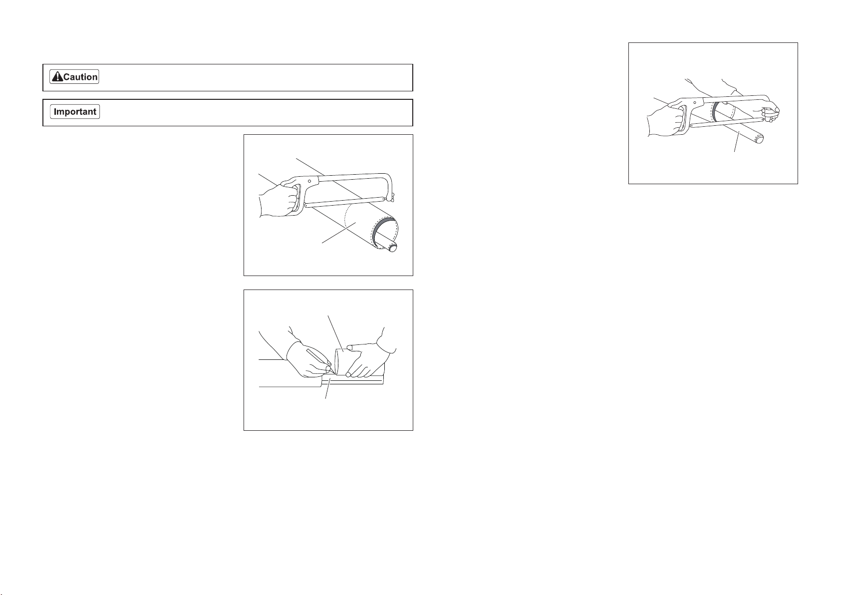
6-4. Method of Cutting Universal Joint
Work with great caution when using a high speed cutter.
The universal joint length depends on the type of tractor to be linked.
1.Hold the half shafts of universal joint next to
each other in the shortest working position
between the tractor and machine, and mark
them.
2.Cut the inner and outer guard tubes at the
marked positions.
3.Mark the shaft at the same length from its
tip as the removed guard tube.
Guard tube
Shaft
Guard tube
4.Cut the inner and outer shafts at the marked
position.
5.Round off all sharp edges, remove burrs and clean the shafts.
−17−
Shaft

−18−
7.Inspections
7-1. Precautions before Inspection
Read “Inspection before work” on the tractor’s owner’s operating manual carefully.
Be sure to stop the engine before inspection, service and adjustment with the tractor
linked.
7-2. Inspection of Covers
If you have removed a protective cover during inspection, be sure to securely install it in
its original position.
If a protective cover remains removed, foreign objects may fly off, possibly resulting in
injuries.
● Make sure that there is no wear or deterioration of protective covers.
● Make sure that there is no damage to protective covers.
● Make sure that there is no interference with moving parts due to deformation of protective
covers.
● Make sure that protective covers are installed in their appropriate positions.
7-3. Inspection of Rollers
Bearing wear due to frequent use or bearing damage caused by water infiltration may
prevent the roller from rotating smoothly.
Inspect the roller and, if necessary, replace parts such as oil seals and bearings.
1.Make sure that there is no abrasion nor adhesion of the roller.
2.Make sure that there is no wear of the roller shaft.
3.Make sure that there is no wear nor damage of the oil seal.
4.Make sure that there is no wear nor rust of the bearing.
5.Make sure that there is no play in the roller shaft.
7-4. Inspection of Tines
Wear gloves when touching tines to avoid cutting your hands.
Vibration from imbalance, dullness or poor discharge of cores may occur due to frequent use
or damage during transportation.
Inspect and, if necessary, replace.
1.Make sure that the tines are not bent.
2.Make sure that the tines are not chipped.
3.Check how much the tines are worn.
The operating depth cannot be maintained if tine wear is 10 mm (0.39 in) or more.
4.Make sure that the edges of tines are not too blunt, making cutting difficult.
5.Make sure that the mounting bolts for the tines are not loose.
6.Check how much the sliding plate of the tine mount section is worn.
7-5. Inspection of Lawn Pressing Plate
Damage may occur due to frequent use or during transportation.
Inspect and, if necessary, replace.
1.Make sure that there is no deformation of the lawn pressing plate.
2.Make sure that there are no cracks or damage to the lawn pressing plate.
3.Make sure that the mounting bolts for the lawn pressing plate are not loose.

−19−
7-6. Inspection of Gear Oil
The oil gauge is located on the side of the gear
box.
1.On a level surface, check that the oil level
reaches the middle of the oil gauge.
2.Check underneath the machine for oil
leakage.
7-7. Supply of Gear Oil
Do not mix different types of oil.
Use BONNOC TS680 (or equivalent) as oil.
1.If the oil level is low, follow the steps below to supply oil.
[1]Open the oil filler cap, and then supply oil through the oil filling port until the oil level
reaches the middle of the oil gauge.
[2]Tighten the oil filler cap securely.
2.On a level surface, check if the oil level is at
the middle of the oil gauge. If necessary,
supply oil.
3.Check underneath the machine for oil
leakage.
7-8. Inspection of Universal Joint
1.Inspect the chain for damage, abnormal wear and so on.
2.Inspect the cover for cracks, damage, abnormal wear and so on.
7-9. Inspection of Oil Leakage
After approximately 50 hours of operation, some joints may be loosened and oil and grease
may leak.
Be sure to retighten the parts.
Check the bottom of the machine for oil and grease leakage.
Chain Cover
Oil gauge
Oil filler cap
Oil gauge
Oil filler cap
Other manuals for TDA1200
1
This manual suits for next models
1
Table of contents
Other Baroness Lawn And Garden Equipment manuals


Popular Lawn And Garden Equipment manuals by other brands


ShelterLogic
ShelterLogic 90476 manual

American Gardener
American Gardener GS36 instruction manual

Premier designs
Premier designs Wind Garden 25948 Assembly instructions

Diivoo
Diivoo WT-03 user manual

Broyhill
Broyhill A414034720 Assembly instructions

Erhardt Markisen
Erhardt Markisen KD Assembly instructions


