CLAYTON MARK 5451 Series User manual

• HEAVY DUTY-BUILT FOR YEARS OF RELIABLE USE
• HIGH STRENGTH STAND PIPE PROVIDES PROTECTION AGAINST DAMAGE
• STAND PIPE HAS SUPERIOR CORROSION RESISTANCE
• STEEL, ZINC PLATED ROD FOR LONG LIFE
• HEAVY DUTY DUAL BYPASS BOTTOM VALVE ALLOWS BETTER FLOW WITH LESS
RISK OF BLOCKAGE FROM DEBRIS
• COMPONENTS CAN BE REPLACED FROM ABOVE GROUND WITHOUT DIGGING
• LOCKING EYE HOLES ALLOW HYDRANT TO BE PADLOCKED WHEN NOT IN USE.
• INLET 3/4” NPT, OUTLET 3/4” GARDEN HOSE THREAD.
ITEM QTY DESCRIPTION MAT'L OF CONSTRUCTION
1 1 HEAD CAST IRON
2 1 HANDLE CAST IRON
3 * 1 CONNECTOR BRASS
4 * 2 LINK STEEL-ZINC PLATED
5 * 1 FULCRUM BOLT STEEL-ZINC PLATED
6 * 1 FULCRUM NUT STEEL-ZINC PLATED
7 * 1 SQUARE HEAD SET SCREW STEEL-ZINC PLATED
8 * 1 PACKING NUT BRASS
9 * 1 PACKING GRAPHITE
10 1 HOSE ADAPTER 3/4" BRASS
11 1 BOTTOM VALVE BRASS
12 1 CLEVIS ROD/ROD ASSEMBLY STAINLESS STEEL/STEEL-ZINC PLATED
13 1 PIPE STEEL, GALVANIZED
14 * 1 PLUNGER BUNA-N/BRASS
* ITEMS ARE INCLUDED IN YRK1 REPAIR KIT.
5451 SERIES
FROST-PROOF YARD HYDRANT
HOW A FROST-PROOF HYDRANT WORKS
CLOSED
The hydrant is closed and no water is in the
riser pipe or head. Water is stopped by the
plunger (valve) below the frost line.
Protected like this, no freezing can occur.
CLOSED - DRAINING
Closing the handle pushes the plunger
down to seal off the water and uncover
the drain hole. This allows the water in
the head and riser pipe to drain back
down into the gravel drain bed. The
hydrant is now empty and cannot freeze.
OPEN - WATER FLOWING
Water is made available by raising the handle.
This will lift the plunger allowing water to flow and
the plunger to seal off the drain hole.
®
LEAVE THIS SHEET WITH END USER.
NOTE: WATER FLOW CANNOT BE THROTTLED.
Hydrant handle must be positioned in the FULL
open position for proper water flow and drainback
seal. This hydrant will not operate properly in a
PARTIALLY open position.

5451 HYDRANT INSTALLATION
5451 HYDRANT ADJUSTMENT PROCEDURE
1. Turn water supply OFF.
2. Open hydrant to relieve pressure.
3. Loosen set screw. (Item 1)
4. Push stainless steel rod down as far as it will go by hand to be sure the plunger is touching the seat.
5. Open handle (Item 2) approximately 30° from closed position.
6. Tighten set screw snugly.
7. Turn water supply ON.
8. Operate hydrant and make sure the hydrant is shutting off properly and flowing properly.
9. If hydrant still does not shut off, repeat steps 1 through 8.
10. Flow water through hydrant and then close completely to check for proper drainage by:
a) listening for water draining down pipe or
b) putting your hand over the hose connection to feel for a vacuum.
If hydrant does not drain, see step 11.
11. To clear drain hole blockage, close off hydrant spout by using hose cap or by attaching and kinking
a hose. Open and close hydrant to allow water pressure to clear blockage. For anti-pollution models, make sure that the small hole in the vent
valve is not blocked or plugged. Repeat step 10 to verify proper drainage. If hydrant still does not drain, repeat steps 1 through 10 to fully
uncover drain hole.
CAUTION: Do not try to make the shutoff adjustment in one attempt or you may overadjust and cause damage to the plunger and rods.
For this reason adjust in multiple small increments.
Liverpool, New York
www.americangranby.com
1. Dig hole for hydrant approximately 2 feet in diameter and 1 foot deeper than the bury depth.
2. FLUSH PIPING BEFORE CONNECTING THE HYDRANT to clear any gravel or other debris that may have
collected in the piping during its installation and assembly. If not flushed out of the piping, this debris
may jam the hydrant mechanism or clog the flow ports.
3. Make the piping connection* but do not bury the hydrant yet. Operate the hydrant to be sure it is oper-
ating properly and the piping connections are not leaking. Open and close the hydrant and check for
flow and drainage. If leakage continues from the drain port see "adjustment procedure" below.
4. Fill the hole around and below the hydrant with medium size gravel. This will provide a drain field for
the hydrant. Without a drain field, the hydrant will not empty itself and it will freeze in cold weather.
This will cause damage to the hydrant and result in loss of water and possible flooding damage.
* CAUTION: USE WRENCH ON VALVE BODY & FITTING ONLY. Do NOT use wrench on stand pipe.
HYDRANT INSTALLATION TIPS
• Never leave hose attached to hydrant after use. This will prevent the hydrant from draining properly
and will allow the hydrant to freeze.
• If the hydrant is to be installed inside a barn or other structure, or if it is installed in asphalt or concrete
such as a driveway, connect a 1/8" drain pipe or tube to the drain port and dig a remote drain field out-
side the structure for the drain pipe to empty into. Without this remote piping and drain field, the water
from the hydrant drainage will percolate up to the surface around or near the hydrant and will damage
the flooring or cause muddy areas in stalls or walkways.
• Water pressure to the hydrant should be regulated to not more than 80 psi. The higher pressures will
accelerate wear and may cause leakage that will saturate the ground and drain field and prevent the
hydrant from draining. If the hydrant is not allowed to drain, it can freeze and cause damage to itself
and cause flooding and loss of water. High pressure will also cause you to have to replace parts and
adjust the hydrant frequently. A normal operating pressure would be 20 to 40 psi.
• Saturated ground in the hydrant drain field can prevent the hydrant from draining and may result in
freezing. If the area where your hydrant is located is low laying or has a tendency to have standing
water, a larger drain field or pit may be required to provide the hydrant a place to drain into.
NOTE: Every 5451 Series hydrant is tested and adjusted at the factory for shutoff at 20 to 40 psi. Adjustment should NOT be necessary
upon normal installation. If installed hydrant does not stop water flow use adjustment procedure below.
American Granby Inc. warrants the products manufactured by us to be free from manufacturing defects for a period of ONE YEAR from
the date of shipment by AGI to the ORIGINAL PURCHASER ONLY. NOTE: The inability to keep water from shutting off is NOT consid-
ered a manufacturer’s defect. Water shut down is considered an adjustment issue or a worn part that needs replacement.
Replacement parts are available from an AGI distributor at end user’s cost.
CAUTION: If a hose is attached to nozzle of hydrant when hydrant is shut off, back siphoning can occur if end of hose is left in container of liq-
uid. The end of hose must be left open to the air so hydrant can drain back. Under no circumstances should CM hydrants drain back into
well or drinking water supply. AGI disclaims all liability of any kind and voids the CM hydrant warranty for installations of this product where it
can or could drain back into a drinking water supply.
Popular Lawn And Garden Equipment manuals by other brands

Black & Decker
Black & Decker 8288 owner's manual
Swisher
Swisher 3279 GRASS CATCHER ATTACHMENT manual

Stiga
Stiga Kitchen installation guide
RedMax
RedMax EXTREME EXZ2450S-PH Owner's/operator's manual
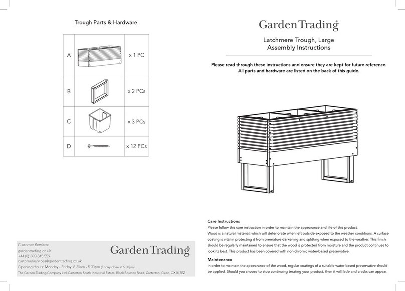
Garden Trading
Garden Trading Latchmere Trough Large Assembly instructions
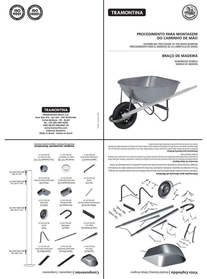
Tramontina
Tramontina 77717421 manual

