Sears 917.253311 User manual

ISearsI
MODEL
NO.
917.253311
461NCH
DOZER BLADE
ATTACHMENT
FOR
SEARS
GARDEN
TRACTORS
OWNER'S
MANUAL
Assembly
Operation
Maintenance
Repair
Parts
Sears,
Roebuck
an
d
Co
.,
Chi
ca
go,
Ill.
60684
,
U.S
.A.
and
Simpsons
Sears
L
im
i
te
d ,
To
ro
n t o ,
Canada
another free manual from www.searstractormanuals.com

TABLE
OF
CONTE
NTS
A
SSE
MBLY
IN
STRUCTIONS
OP
E
RAT
ION
IN
S
TRU
CTIONS . 1
.4
MA
I
NTENAN
CE
IN
STRUCTIONS .
REPAIR
PART
S . • . 4
. 5
nooOOl
ooooooomoo
WARRANTY
FULL ONE YEAR
WARRANTY
For
one
year
from
date
of
purchase,
Sears will
repair
any
defect
in
mat
erial
or
wo
r
kmansh
ip
in
this
tractor
attachm
ent,
at
no
charge.
If
the
tractor
attachment
is
used
for
commercial
or
rental
pur
poses,
this
warranty
app
lies
for
onl
y
thirty
day
s fr
om
date
of
pu
rc
hase.
Warranty
~"r
vice
is
avail
able
by simply
contacting
your
nearest Sears
store
throughout
the
United
States.
This w
ar
r
ant
y gives
you
specific legal rights,
and
you
may
have
other
rights
which
vary
from
state
to
state
.
SEA
R
S,
ROEBUCK
AND
CO.
Sears
Tow
er
BSC 41-3
Chicago, IL
60684
RULES
FOR
SAFE
OPERATION
1.
Know
the
control
s
and
how
to
stop
qu
ickl
y.
READ
TH
E
0WI\IER'S M
ANUAL.
2.
Do
not
all
ow
childr
en
to
operate
th
e vehicle. Do
not
allow
adu
lt
s
to
operate
it
without
proper
in
struction
.
3.
Do
not
carry
passengers. Keep
children
and
pets
a safe dis·
tance
awa
y.
4. Always wear substantial
footwear.
Do
not
wear
loose fitting
clothing
that
could
g
et
caught in moving
pa
rts.
5.
Keep
your
eye
s
and
mind
on
your
tractor,
mower
and
the
area being
cut
.
Don't
let
other
interests
di
stract
you.
6.
Do
not
attempt
to
operate
y
our
tractor
or
mower
when
n
ot
in drivers
seat.
7. Al
ways
g
et
on
or
off
your
tractor
from
the
ope
r
at
or
s l
eft
ha
nd
side.
8. Cl
ear
the
w
ork
ar
cn
of
objects
whi
ch
might
be
picked
up
and
thrown.
9
.-
Disengage all
attJchment
clutches
and
shift
into
neutral be·
f
ore
attempti
ng
to
start
the
engine.
10
. Disengage
power
to
attac
hme
nts
and
stop
the
engine be-
fore leaving
the
op<'rat
or's
position.
11. Disengage p
ower
to
mower
,
stop
th
e engine
and
disconnect
spark
plug wire(s) from
spark
plug(s)
before
cleaning,
making
an
adju
stment
or
repairs.
12. Disengage
power
to
attachments
wh
en
tra
nsporting
or
not
in use. Drive slowly
when
front
or
rear
mo
unted
a
ttac
hment
is
in t
ransp
ort
position.
13. T
ake
all possible
precautions
when
leaving
the
vehicle
un
-
a
ttende
d,
such
as disengaging
the
power
-
take-off
, lowering
the
attachment
s, shifting
into
neutral
,
settin
g
the
park
ing
brake,
stopping
the
engine,
and
remov
ing
the
key
.
14
.
Do
not
stop
or
start
suddenly
when
going
uphi
ll
or
down·
hilb Mow
up
and
down
the
face
of
slopes
(no
t
greater
th
an
15
); never across
the
face.
15.
Reduce
speed
on
slopes
and
make
turns
gradually to
pre
-
vent
tipping
or
loss
of
control.
Exercise
extreme
caution
w
hen
changing
direction
on
slopes.
16
.
Do
not
sh
ift
gears while going
up
or
down
slopes.
Choose
a gear
low
enough
to
negotia
te
the
slope
without
stopping
and
shift
ing gears.
To
r
educe
speed,
move
t
hr
ottle
lever
to
slow.
17
. Never
mow
in
w
et
or
sl
ippery grass,
when
traction
is
un
·
s
ure
or
at
a speed
wh
ich could cause a skid.
18.
Stay
alert
for
hole
s
in
the
terrain
and
other
hidden
hazard
s.
19
.
Do
not
drive
too
close
to
cr
eeks
,
ditc
hes
and
public high-
ways.
20. Exercise special care
when
mow
ing
around
fi
xed
objects
in o
rder
to
prevent
the
blades
from
striking
them.
Never
de
liberately
run
tractor
or
mower
into
or
over
any
foreign
ob
ject
.
:l
l.
Never
shift
gears u
nt
il
trac
tor
comes
to
a
stop
.
22. Never place
hands
or
f
eet
under
the
mow~r
.
in
the
defl<>o
to•
(discharge c
hut
e)
or
n
ea
r
aroy
m
ov
ing
parts
wf
1i
fe
t•
~t
.
t
o
•
or
mower
are
runni
ng.
Alway
~
i<eep
clear of
dis~;barge
chu
t<>
.
23.
Us
e care
when
pulling loa
ds
or
using
heavv
~quipme
nt.
a. Use
only
approved
dr
awbar
hitch
points.
b. Limit loads
to
t
hos
e y
ou
can
safely
co
n
trol.
c.
Do
not
turn
sharply.
Use care
when
backing.
d.
Use
counte
rweights
or
wheel weights anrl tire
c
h~ins
when
suggested in
this
owner's
manual.
e. Never
run
Dozer
Blade
into
heavy
material
at
high
s
peeds.
It was designed f
or
light
work
and
should
Po l
he
used
for
heavy
do
zing.
24.
Watch
out
for
traffic
when
crossing 0 1
ne
ar
roadway
s.
25. When using
an
y
attachments,
never
direct
discharge
nf
material
toward
by
standers
nor
allow
anyone
near
th
e ve-
hicle while
in
ope
ration.
26. Handle gasoline
with
care -
it
is
11ighly
flamma
bl
<>
.
a. Use
approved
gaso
li
ne
contain
ers
b. Never remove
the
cap
of
the
fuel
tank
or
add
g~s
olin
"
to
a
running
or
hot
engine,
or
fill the fuel
tan
l<
indoor
~
.
Wipe
up
spilled gasoline.
c.
Op
en
doors
if
the
engine
is
run
in
the
garage ·
exha
ust
fumes are dangerous.
Do
not
run
the
eng
ine
indoor
s.
27. Keep
the
vehicle
and
attachments
in
good
operating
c
on
·
dition
,
and
keep
safety
de
vi
ces in
pl
ace. W
hen
using
Thre
e
Point Hitch
remove
attachm
ent
from
hitch
before
ma
k
in
g
any
repairs
on
attachment
or
h
itch.
28. Keep all
nuts,
bol
ts
and
screws
tight
1all cotter pins
and
re-
tainer
springs in place
to
be
sure
the
equ
ipmen
t
is
in safe
working
condi
tio
n.
29. Never
store
the
equipment
with
gasoline in t
he
tank
inside
a building
where
fumes
may
reach an
ope
n flame
or
spar
k.
Allow
the
engine
to
cool
before
stor
ing
in
any
enclosur
e.
30.
To
reduce
fire
hazard,
keep
the
eng
i
ne
free
of
grass, leaves
or
exce
ssive grease.
31.
The
vehicle
and
attachments
should
be
sto
pped
and
i
nspect·
ed
for
damage
after
str
iking a foreign
object
,
and
the
dam-
age
should
be
repaired
before
restart
in
g
and
operating
the
equ
ipment.
32.
Do
not
change
th
e engine governor settings
or
ove
rs
peed
the
engine.
33. When using
the
vehicle w
it
h
mower,
proceed
as follows:
a. Mow
only
in
day
l
ight
or
in
good
artifici
al
li
ght
.
b. Never
make
a
cutt
ing
height
Cldjustme
nt
while
the
engine
is
running
if
the
operator
must
dismount
to
do
so.
c.
Shut
the
engine
off
when
rem
ov
in
g
the
grass ca
tc
her
or
unclogging
chute.
d.
Check
the
blade
mounting
bo
l
ts
for
proper
tightness
at
frequent
int
ervals.
34.
Check
th
e grass
ca
tcher
bags
frequently
for
wear
or
de
terio
·
ration
. Replace
with
new
bags
for
safety
protection
.
A LOOK
FOR
THIS
SYMBOL
TO
POINT
OUT
IMPORTANT
SAFETY
PR
ECAUTIONS. IT MEANS--ATTENTION! BECOME
ALERT! YOUR
SAFETY
IS INVOLVED.
another free manual from www.searstractormanuals.com

!~
FIGURE
1
ASSEMBLY
YOUR DOZER
BLADE
MUST BE
ATTACHED
WITH FRONT MOUNTING
BRACKET
25314
OR
25317.
1. Remove shipping wires, channel, blade, and lever assemblies
and
Bag
of
Par
ts
from
carton.
To
assemble
your
Dozer
you
will
need:
(2)
1/2"
Wrenches (1)
5/32"
Allen Wrench
(2)
9/16"
Wrenches (1) Pliers
(2)
15/16"
Wrenches (1) Hammer
NOTE: Right Hand (R.H.) and
Left
Hand (L.H.
.)
are
deter·
mined
from
operator's position.
IF
YOUR TRACTOR IS A ONE-PIECE REAR FENDER
MODEL
SHOWN IN FIG.
1,
BEGIN ASSEMBLY WITH STEP
2.
-OR-
IF
YOUR TRACTOR IS A TWIN
CYLINDER
MODEL,
BEGIN ASSEMBLY WITH STEP 3.
-OR-
FOR
All
OTHER TRACTOR MODELS, BEGIN ASSEMBLY
WITH STEP 4.
2.
Assemble Control Rod Guide (shipped in
Bag
of
Parts)
to
[]illij•@@©
Hex Bolt, Flat
Washer,
Lockwasher and Hex
Nut
(shown
full
size
above) found in
Bag
of
Parts
.
a.
Remove Engine Pulley Cover (Fig. 2).
b. Insert Hex
Bolt
through
Chassis
Channel
from
the inside.
c.
Place
Control Rod Guide, Flat
Washer,
Lockwasher and
Hex
Nut
on
Bolt
and tighten securely.
d. Replace Engine Pulley Cover and Complete Dozer
assem-
bly starting
with
step 5,
page
2.
3. Assemble Control Rod Guide
to
Tractor:
a.
Remove Cover (Fig. 3).
b. Loosen
Muffler
Guard Bracket Bolt.
c.
Place
Control Rod Guide
on
Bolt
between Flat
Washer
and Bracket and tighten securely.
d. Replace Cover and complete Dozer assembly starting
with
step 5,
page
2.
4. Assemble Control Rod Guide
to
Tractor:
a. Remove Cover (Fig. 4).
b. Loosen Hex Bol
t.
c.
Place
Control Rod on
Bolt
between Flat
Washer
and
Chassis
Channel and tighten securely.
d. Replace Cover and complete Dozer assembly starting
with
step 5,
page
2. . , .
·---------•
FIGURE 2
another free manual from www.searstractormanuals.com

UPPER
MOUNTING
BRACKET--=-
--
,..,
LOWER
MOUNTING
-~---------~
BRACKET
FIGURE 5
5. Assemble Dozer Channel
to
Mounting Bracket using:
Hex
Bolt,
Flat Washer, Lockwash
er
and
two
Hex Nuts
(shown
full
size
above) found in
Bag
of
Par
ts.
a. Start Hex
Bolt
from
under Lower Mounting Bracket
just
far enough
to
hold Flat
Washer
on
top
side
of
Lower
Mounting Bracket.
b. Insert Dozer Channel between Upper and Lower Mount-
ing Brackets and slide Hex
Bolt
through.
c. Add lockwasher and one Hex
Nut
and tighten securely
(Back
Nut
off
sl
ightly
if
necessary
to
allow Channel
to
rotate freely).
d. Add second Hex
Nut
and tighten securely.
CONTROL
ARM
CONTROL
ARM
PIN
LOWER
CONTROL
ROD
EVE
DOZER
CHANNEL
SHAFT
6.
Assemble R.H. Plate and L.H. Bracket
to
ends
of
Dozer
Channel Shaft using:
two
Kliprings (shown
tull
size
above) found in
Bag
of
Parts
(Fig.
5)
.
7. Assemble
Lift
Lever Shaft
to
R.H. Plate using:
Flat
Washer
and Cotter Pin (shown
full
size
above) found in
Bag
of
Parts. Swing R.H. Plate up and position on
Lift
Leve
r Shaft, place Flat
Washer
over shaft and
secure
with
Cotter Pin.
8. Assemble
Lift
Bracket on
Lift
Bar using:
Lift
Pin
and Retainer Spring (shown
full
size
above) found
in
Bag
of
Parts. Insert
lift
Pin
through
Lift
Bracket holes
and
Lift
Bar
slot and
secure
with
Retain
er
Spring (Fig. 5).
_ 2 _9.
Place
lower
Control Rod Eye in Control
Arm
Hole (Fig. 5).
}
'
another free manual from www.searstractormanuals.com

Flat
Washer
and Retainer Springs (shown
full
size above)
found in
Bag
of
Parts. Insert Control
Arm
Pin
into
R.H.
Plate, place Flat Washer on Pin and secure
with
Retainer
Spring (Fig. 5).
11
.
If
necessary, loosen Set Screws
to
position
Lift
Bracket on
Lift
Lever Shaft
so
that
Bracket lines up
with
Lift
Bar.
Tighten
both
Set Screws securely.
12.
Place
a 2 x 4
or
similar object flatwise beneath
each
end
of
Blade (Fig. 6).
13. Insert Pivot
Pins
of
R.H. Plate
and
L.H. Bracket
into
Front
Mounting Bracket slots (Fig.
6-
Inset).
14. Turn
front
tractor
wheels
to
the right to assemble
Mount·
ing Rod
and
Retainer Spring (furnished
with
Front
Mount-
ing Bracket)
thru
holes in R.H. Plate, L.H. Bracket and
Front
Mounting Bracket. Secure
with
Retainer Springs
to
the inside (Fig.
6-
Inset).
15. Install Control Rod using:
@
~I
FIGURE 6
16. Remove 2 x 4's
from
beneath Blade.
17.
Adjust
Control Chain.
a.
With Control Rod handle in Blade Ang
le
"Set"
Pos
ition
(Fig. 6).
Cha
in must
be
long enough
to
allow
Return
Spring
to
pull Latch Pin
into
Blade Angle Adjustment
holes directly below (Fig. 6 - Inset).
b. Wi
th
Control Rod handle in Blade Angle
"Adjusting"
Position (Fig. 6). Chain must
be
short enough
to
pull
Latch Pin
from
Blade Angle Adjustment holes (F
ig
. 6 -
Inset).
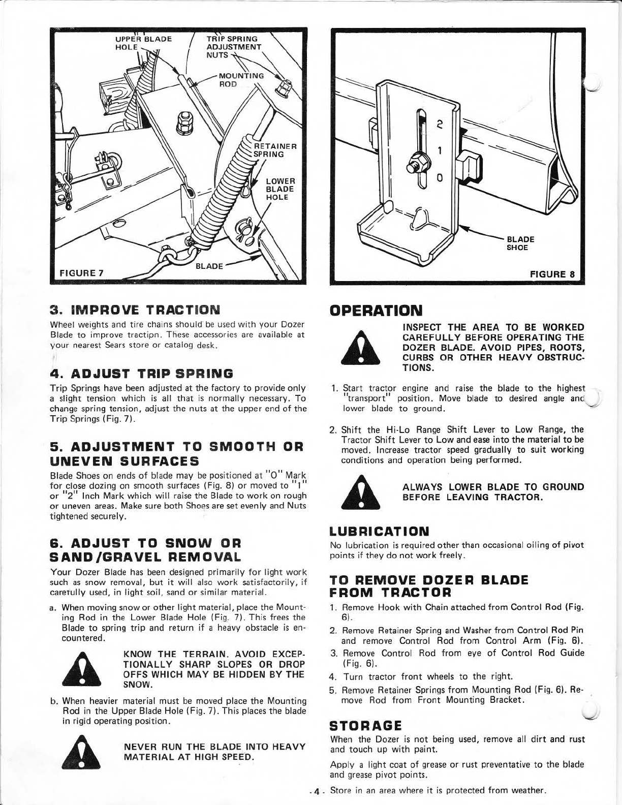
18. Tighten Jam Nuts
sh
ipped on
Tr
ip Spring Bolts
until
a
sl
ight
spring tension is achieved
and
enough threads
are
ex-
posed
to
add:
Jam Nuts (shown
full
size
above) found in
Bag
of
Parts.
Tighten securely.
ADJUSTMENTS
1. Ll
FT
BLADE
Lift
Blade
from
ground before changing blade angle
or
trans·
porting.
a.
Squeeze
Lever Plunger (Fig. 6).
b. Move Lever
to
Lowest position on Lever Quadrant and
re
·
~
l
ease
Plunger
to
hold
this position.
c=::!J
2 . ANGLE BLADE
Flat Washer, Retainer Spring,
two
Hooks, Control Chain,
and Return Spring
found
in
Bag
of
Parts.
a.
Insert Control Rod
into
eye
of
Control Rod Guide
(Fig. 6).
b.
Place
Control Rod Pin
into
Control
Arm
Bushing, place
washer over Pin and
secure
with
Retainer Spring (Fig. 6
-Inset).
c.
Assemble
two
Hooks
into
Latch Lever and Control Rod
Strap (Fig. 6 - Inset).
d. Connect Control
Cha
in
to
hooks (Fig.
6-
Inset).
e. Assemble Return Spring
to
Latch Lever and Dozer
Channel (Fig, 6 - Inset). .
3.
There
are
five blade
pos
itions; straight ahead, and
two
distinct
angles
to
the right
or
left.
ALWAYS
LIFT
BLADE
FROM
GROUND TO CHANGE
ANGLE
PREVENTING
STRAIN
ON
ANGLE
CONTROL
LINKAGE.
a.
Turn Control Rod
to
Blade Angle
"Adjusting"
Position
(Fig. 6). .
b.
Push
or
Pull Rod
to
desired
an9tle.
c.
Turn Control Rod
to
Blade Angle
Set"
Position. Make sure
Latch Pin catches in one
of
the five Blade Angle
Adjustin~
Holes (Fig.
6-
Inset).
another free manual from www.searstractormanuals.com

FIGURE 7
3.
IM
PROVE
T
RA
CTION
Wheel weights and tire chains should'
be
used
with
your
Dozer
Bl
ade
to
improve tractipn.
These
accessories
are
available at
your nearest
Sea
rs store or catalog desk.
4 .
ADJUST
TRIP
SPR
ING
Trip
Springs have
been
adjusted at the factory
to
provide
only
a slight tension which
is
all
that
is
normally necessary.
To
change spring tension, adjust the nuts at the upper end
of
the
Trip
Springs (Fig. 7).
5.
ADJUSTMEN
T TO
SMOO
TH
OR
UNEVEN
SURFACES
Blade
Shoes
on ends
of
blade may
be
pos
it
ioned
at
"o" Mark
for
close dozing on smooth surfaces (Fig. 8)
or
moved
to
"1"
or
"2'' Inch Mark which
will
raise
the Blade
to
work
on rough
or
uneven
areas
. Make sure
both
Shoes
are
set evenly and Nuts
tightened securely.
6.
ADJUST
TO
SNO
W OR
SAND/GRAVEL
REMO
VAL
Your
Dozer Blade
has
been
designed
primarily
for
li
gh
t
work
such
as
snow removal,
but
it
will
also
work
satisfactoril
y,
if
carerully used, in
light
soil,
sand
or
similar material.
a. Wh
en
moving snow
or
other
light
material, place the
Mount
·
ing Rod in the Lower Blade Hole (Fi
g.
7).
Th
is frees the
Blade
to
spring
trip
and return if a heavy obstacle
is
en-
countered.
KN
OW THE TERRA
IN
.
AVO
ID
EXCE
P-
TI
ONAL
LY
SHARP SLOP
ES
OR DROP
OFFS WHICH
MAY
BE
HIDDE
N BY THE
SNOW.
b. When heavier material must
be
moved place the Mounting
Rod in the Upper Blade Hole (Fig. 7). This places the blade
in rigid operating position.
NEVER RUN THE BL
AD
E
INTO
HEA
VY
M
AT
ERI
AL AT
HIGH SP
EE
D.
FIGURE 8
OPERATION
IN
SPECT
THE AREA TO
BE
WORKED
CAREFULLY BEFORE OPERATING THE
DOZER BLADE. AV
OID
PIPES
, ROOTS,
CURBS OR OTHER
HEAVY
OBSTRUC·
TI
ON
S.
1. Start
tractor
engine and
raise
the blade
to
the
highest
"t
r
ansport"
position. Move blade
to
desired angle
an
d
lower blade
to
ground.
...-
2.
Shift
the
Hi-Lo
Rang
e
Shift
Lever
to
Low Range,
th
e
Tractor
Shift
Lever
to
Low and
ease
into
the material
to
be
moved. I
ncrease
tractor
speed
gradually to s
uit
wor
ki
ng
conditions and operation being performe
d.
A
LW
AYS
LOWER
BLADE TO GROUND
BEFORE LEAVING TRACTOR.
L
UBRICATION
No lubrication
is
required other than occasional
oiling
of
pivot
points if they
do
not
work
freely.
TO
REMOVE
DOZER
BLADE
FROM
TRACTOR
1. Remove
Hook
with
Chain attached
from
Control Rod {Fig.
6).
2. Remove Retainer Spring and
Washer
from
Control Rod Pin
and remove Control Rod
from
Control Arm (Fig. 6).
3. Remove Control Rod
fr
om eye
of
Control Rod Guide
(Fig. 6).
4. Turn
tractor
front
wheels
to
the right.
5. Remove Retainer Springs
from
Mounting Rod {F
ig
. 6). R
e-
move Rod
from
Front
Mounting Bracket.
STORAGE
When the Dozer
is
not
being used, remove all
dirt
and rust
and touch up
with
paint
.
Apply
a light coat
of
grease
or
rust preventati
ve
to the blade
and
grease
pi
vot
points.
. 4 . Store in
an
area
where
it
is
protected from weather.
another free manual from www.searstractormanuals.com

•
REPAIR
PARTS
DOZER
BLADE
--
MODEL
NUMBFn
917.253311
A B C D
I
··
I·
·
~::(jj
1
s.
(il)531
,__
__
,
=
49
c:=a::::J
50
t:::z::::l
50
cr:::IJ
51
cril
51
E F G
1
57
Cifl58
'59
I
=-=60
=50
CI:I:l47
==
14
c:r::I)5
1
=5
2
([I)
53
G
G
2
s/
T:Z--
===
55
f//
@--~
:
35
36
D 28 27
\.l
~
/31
23~~
~
'i~
~
~
t
14
,...._-4j,J.-_46
lr
7
\,
16
17
~
18
18-o
---#1'---
-14
KEY
PART
KEY
PART
DESCRIPTION NO. NO.
NO. NO. 32 9842R Pin
Bracket·
L.H.
673A72
Bl
ade
Weldment
33
673A84 Bracket L.H. Weldment
34 9436R Return Spring
2 9359R
~hoe
35 9906R Roll Pin
3 9273R
Mount
ing Rod 36 9843R
latch
Pin Lever
4
49
41M Retainer Spring 38 450
2P
Set Screw, Hex Socket Hdless. ·
C.P.
5 673A71 Mountin!l Brackets Upper and Lower
5/11>
· 18 UNC x
5/16
6 1590P
Washer
27/32
x 1 · 1
/4
x
16
Ga. 39 673A82
lift
Bracket
7 2521P Cotter Pin
3/16
x 1 - 1
/2
40
2228M
Woodruff
Kev 3/16
.2<
3/4
8 9463R U-Bolt
41
2505P
Cott
er Pin 1
/8
x
3/4
9 9466R
Tri,J?
Spring 43 4338M Lever Clip · Lower
10
9464R
"8
Hook 44
673A129
Lift
Lever and Shaft
11
70J Control Chain 45 29J L
ever
Plunger
12 9440R Control Rod Lower 46 1539U1 Compression
Spr
i
ng
-
13 4939M Retainer Spring 47 STD541025 •Hex
Nut
1/4
· 20 UNC
14 STD551037 *Washer 13/32 x 13/16 x
16
Ga.
48
STD533110
•c
arriage
Bolt,
Sq.
Neck Sht. Shoulder
15
673A90
Control Rod Weldment
5/16
· 18 UNC x 1
16
673A88
Control
Arm
Weldment
49
STD551031
"Wa
sher
11
/
32x
11/16x
16Ga.
17 673A
101
Control Rod Guide 50 STD551131 " loc:-.vasher 5/16
18 5845R Klipring
51
STD541031 "Hex
Nut
5/16
· 18 UNC
19
673A83
Plate Weldment · R.H. 52 STD551137 •lockwasher
3/8
20 673A87
Pin
and Bracket Weldment 53 STD541037 "Hex
Nut
3/8
· 16 UNC
21 9451R
Lift
Bar 54 3352P Hex Bolt 1/2 · 13 UNC x 4 · 1/2
22
673A73
Channel Weldment 55 STD551050 *Washer
17/32
x 1 x 16 Ga.
23 9462R Drilled
lift
Pin 56 STD541050 *Hex
Nut
1/2
-13
UNC
25 15
70P
Washer
21
/3
2 x 2 ·
1/8
x 16 Ga. 57 STD523712 *Hex
Bolt
3/8
· 16 UNC x 1 · 1/4
26 3050P Hex
Bolt
5/8
·
11
UNC x 4 ·
1/2
58 STD523108 "Hex
Bolt
5/16
· 18 UNC x 7/8
27 STD551162 * Lockwasher
5/8
59 STD522507 *Hex
Bolt
1/4 · 20 UNC x 3/4
28 STD541062 *Hex
Nut
5/8
·
11
UNC 60 STD551125
•loc
kwasher 1
/4
29 9446R
Trip
Sh
aft
9912R Warranty
Tag
30
9445R Latch Pin 32J Owners Manual
31
9841 R Pin Bracket · R
.H
.
*STANDARD
HARDWARE-
-PURCHASE
LOCALLY
. 5 .
2
~
en
,.....::)
"":
c:
,.....
·-
c:i]
N..,
.,
c:
N
·;:
MO..
another free manual from www.searstractormanuals.com

ISearsI
MODEL
NO.
917.253311
HOW
TO
ORDER
REPAIR
PARTS
MODEL
NUMBER
The Model Number
will
be
found on a plate on the
left
side,
attached
to
the
Lift.
Bracket. Always mention the Model
Number when requesting
service
or
repair parts
for
your
Dozer Blade.
REPAIR PARTS
All parts listed herein may
be
ordered from any SEARS,
ROE-
BUCK
AND
CO
.
or
SIMPSONS-SEARS LIMITED retail
or
cataloq store.
WHEN
OR
DERING REPAIR PARTS, ALWAYS GIVE THE
FOLLOWING INFORMATION:
e THE PART NUMBER
e THE PART DESCRIPTION
• THE MODEL NUMBER
e THE NAME
OF
MERCHANDISE
If
the parts you
need
are
not
stocked locally, your order
will
be
electronically transmitted
to
a
Sears
Repair
Parts
Distribution
Center
for
"expedited handling".
\
Sears
.
Roebuck
and
Co
..
Chicago.
Ill
.
60684.
U.S.A .
and
Simpsonii
Sears
Limited
.
Toronto
.
Canada
another free manual from www.searstractormanuals.com
Table of contents
Other Sears Lawn And Garden Equipment manuals

Sears
Sears 917.250550 User manual

Sears
Sears 180.260250 User manual

Sears
Sears Craftsman 316.794450 User manual

Sears
Sears 486.244031 User manual

Sears
Sears 486.244062 User manual

Sears
Sears 917.252031 User manual

Sears
Sears Craftsman 900 Series User manual

Sears
Sears BugWacker 557-5199 User manual

Sears
Sears 917.253010 User manual